Sélection de la langue

Search

Sommaire du brevet 1334739 

Énoncé de désistement de responsabilité concernant l'information provenant de tiers

Une partie des informations de ce site Web a été fournie par des sources externes. Le gouvernement du Canada n'assume aucune responsabilité concernant la précision, l'actualité ou la fiabilité des informations fournies par les sources externes. Les utilisateurs qui désirent employer cette information devraient consulter directement la source des informations. Le contenu fourni par les sources externes n'est pas assujetti aux exigences sur les langues officielles, la protection des renseignements personnels et l'accessibilité.

Disponibilité de l'Abrégé et des Revendications

L'apparition de différences dans le texte et l'image des Revendications et de l'Abrégé dépend du moment auquel le document est publié. Les textes des Revendications et de l'Abrégé sont affichés :

  • lorsque la demande peut être examinée par le public;
  • lorsque le brevet est émis (délivrance).
(12) Brevet: (11) CA 1334739
(21) Numéro de la demande: 1334739
(54) Titre français: REDUCTEUR DE VITESSE ET DISPOSITIF DE FREINAGE POUR ELEVATEUR A COMMANDE ELECTRIQUE
(54) Titre anglais: GEAR REDUCTION AND BRAKING MEANS IN A MOTOR DRIVEN ELEVATING SYSTEM
Statut: Périmé et au-delà du délai pour l’annulation
Données bibliographiques
(51) Classification internationale des brevets (CIB):
  • B66B 11/04 (2006.01)
(72) Inventeurs :
  • HEIKKINEN, URHO (Finlande)
(73) Titulaires :
  • KONE ELEVATOR GMBH
(71) Demandeurs :
  • KONE ELEVATOR GMBH (Suisse)
(74) Agent: G. RONALD BELL & ASSOCIATES
(74) Co-agent:
(45) Délivré: 1995-03-14
(22) Date de dépôt: 1989-07-06
Licence disponible: S.O.
Cédé au domaine public: S.O.
(25) Langue des documents déposés: Anglais

Traité de coopération en matière de brevets (PCT): Non

(30) Données de priorité de la demande:
Numéro de la demande Pays / territoire Date
883244 (Finlande) 1988-07-07

Abrégés

Abrégé anglais


An elevator machine has a drive motor, a drive
shaft driven by the motor, a traction sheave transmitting
the motion to an elevator car by means of ropes and a gear
assembly to reduce the rotational speed of the motor for
the traction sheave. The gear assembly is located inside
the traction sheave, the drive shaft passes through the
traction sheave, the drive motor is coupled to one end of
the drive shaft and the brake is mounted on the other end
of the opposite side of the traction sheave.

Revendications

Note : Les revendications sont présentées dans la langue officielle dans laquelle elles ont été soumises.


THE EMBODIMENTS OF THE INVENTION IN WHICH AN EXCLUSIVE
PROPERTY OR PRIVILEGE IS CLAIMED ARE DEFINED AS FOLLOWS:
1. An elevator machine comprising:
a drive motor;
a drive shaft driven by said drive motor, said
drive shaft being provided with gear teeth which are adapted
to mesh with one or more intermediate gears;
said drive shaft being rotatably mounted with
bearings inside a fixed supporting axle;
said fixed supporting axle comprising one or more
tubular parts and one or more flanges interconnected by one
or more connecting members placed on the periphery of said
flanges and rendering said supporting axle rigid, and
wherein said one or more flanges support one or more
intermediate gears between them, said one or more
intermediate gears purposed to intermesh with said teeth of
said drive shaft;
a traction sheave adapted to transmit motion of
said drive shaft to an elevator car by means of cables;
said traction sheave being provided with internal
toothing purposed to engage with said intermediate gears;
said intermediate gears comprising a gear assembly
to reduce rotational speed of said drive motor for said
traction sheave, said gear assembly being located inside
said traction sheave;
said drive shaft passing through said traction
sheave, said drive motor being coupled to one end of said
drive shaft and a brake being mounted on the other end of
said drive shaft on the opposite side of said traction
sheave.
2. An elevator machine according to claim 1,
wherein said intermediate gear is rotatably mounted with
bearings on its axle.
3. An elevator machine according to claim 1,
wherein said brake is fixed to a frame plate of said
elevator machine opposite said drive motor.

4. An elevator machine according to claim 1,
wherein the side walls of said traction sheave are of a
massive construction so as to dampen the noise generated by
the gear assembly.
5. An elevator machine according to claim 1,
wherein said fixed supporting axle comprises two tubular
parts and two flanges interconnected by three connecting
members placed on the periphery of said flanges at an
angular distance of 120° from each other.

Description

Note : Les descriptions sont présentées dans la langue officielle dans laquelle elles ont été soumises.

1334739
The present invention relates to an elevator
machine, more particularly it relates to an elevator
machine consisting of a drive motor, a drive shaft driven
by the motor, a traction sheave adapted to transmit motion
of the drive shaft to an elevator car by means of ropes,
and a gear assembly to reduce the rotational speed of the
motor for the traction sheave.
The most common type of reduction gear used
between a drive motor and a traction sheave of an elevator
is a worm gear. However, the worm gear has a relatively
low efficiency and there has been a trend towards the use
of other types of reduction gear. Worm gears have been
replaced, for example, by spur gears which have a better
efficiency, especially at start-up. However the gear
assemblies of spur gears are bulky and therefore
impractical.
An object of the present invention is to create
an elevator machine that is more efficient than machines
using a worm gear and less bulky than those using spur
gears.
According to the present invention, there is
provided an elevator machine, consisting of a drive motor,
a drive shaft driven by said drive motor, a traction sheave
adapted to transmit motion of said drive shaft to an
elevator car by means of suspension ropes, and a gear
assembly to reduce rotational speed of said drive motor for
said traction sheave, said gear assembly being located
inside said traction sheave, said drive shaft mounted with
bearings inside a supporting axle, said drive shaft passing
through said traction sheave, said drive motor being
coupled to one end of said drive shaft and a brake being
mounted on the other end of said drive shaft on the
opposite side of said traction sheave.
In a preferred embodiment of the invention the
drive shaft is provided with a toothing which is purposed
to mesh with one or more intermediate gears mounted with
bearings on fixed axles.
-- 1 --

1334739
In another preferred embodiment of the invention
- the traction sheave is provided with internal toothing
purposed to engage at least one intermediate gear.
In yet another preferred embodiment of the
invention the drive shaft is mounted with bearings inside
a supporting axle and the bearings are located in the axial
direction on either side of the toothing of the drive
shaft.
Further features and advantages of the invention
will become apparent to those skilled in the art from the
following description thereof when taken in conjunction
with the accompanying drawings, in which:
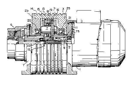
Figure 1 is a side view of an embodiment of the
machine of the invention in partial cross-section; and
Figure 2 is a side elevational view of the
traction sheave, reduction gear, and an elevator car and
counterweight suspended on the traction sheave, with
suspension ropes passing around the traction sheave.
Referring to Figure 1, a drive motor 1 powers a
drive shaft 2. The drive shaft 2 extends through the hub
of a traction sheave 3 and is coupled to a brake 6 on the
other side of the traction sheave 3. The brake 6,
preferably a disc brake, is fixed to the frame plate 7 of
the elevator machine.
The drive shaft 2 is provided with a toothing 8
which meshes with a toothing 12 of a rotating intermediate
gearwheel 5. Figure 2 shows three intermediate gearwheels
5 but any number of intermediate gearwheels 5 is possible.
The intermediate gearwheel 5 meshes with the traction
sheave 3 via a toothing 13 provided on the interior surface
of the rim of the traction sheave 3. Preferably, a helical
gearing is used, the helix angle and contact width of the
teeth being selected such that the sum of the transverse
contact ratio and the maximum contact ratio is as close as
possible to an integer value, for example three. Such
selection of the helix angle and contact width ensures that
the total length of the pressure line and the engagement

133~739
rigidity remain constant during engagement, resulting in
-~ even tooth contact and low noise levels. When the drive
motor 1 rotates the drive shaft 2, the latter rotates the
intermediate gearwheel 5, which, in turn, rotates the
traction sheave 3. The rim of the traction sheave 3 is
provided with a number of grooves 14, formed in a known
manner and located side by side, for suspension ropes 4 as
shown in Figure 2.
The drive shaft 2 is surrounded by a supporting
axle ll consisting of two tubular parts adjoining the
intermediate gearwheel 5. Each of the tubular parts is
provided with a flange 15, 16 at the end thereof which
faces the intermediate gearwheel 5. The flanges 15, 16 are
interconnected by connecting members 24 shown in Figure 2,
to make the supporting axle 11 rigid. There may be, for
example, three connecting members 24 which are placed on
the periphery of the flanges 15, 16 at an angular distance
of 120 from each other. The drive shaft 2 is supported
inside the supporting axle 11 by two bearings, which
preferably are placed at the points 22 and 23 located
axially on either side of the drive shaft toothing 8.
A fixed axle 17 is provided between the flanges
15 and 16. The intermediate gearwheel 5 is rotatably
mounted on the fixed axle 17 with bearings 18, 19.
The traction sheave 3 is rotatably mounted on the
supporting axle 11 with bearings 20, 21. The bearings 20,
21 preferably located axially on either side of the
intermediate gearwheel 5.
Referring now to Figure 2, three intermediate
gearwheels 5 are mounted inside the traction sheave 3
between the drive shaft 2 and the interior surface of the
rim of the traction on sheave 3. When the drive shaft 2
rotates, the intermediate gears 5 transmit the rotational
power to the traction sheave 3, which in turn moves the
elevator suspension ropes 4 with the aid of friction. An
elevator car 9 is suspended at one end of the suspension
ropes 4 while a counterweight 10 is attached to the other

1334739
end thereof. It will be appreciated by those skilled in
the art that the suspension system may include one or more
diverting pulleys (not shown).
The side walls 25 of the traction sheave 3 may be
made especially massive to insulate the noise generated by
the toothing 8, 12, 13 contacts between the intermediate
gearwheel 5.
It will be appreciated by those skilled in the
art that the invention is not restricted to the embodiments
disclosed above, but may instead be varied within the scope
of the following claims without departing from the spirit
and scope of the invention. For example, the brake 6 need
not necessarily be constructed as shown in Figure 1, but
other types of brake can be used instead. However, if the
brake 6 is mounted on one end of the drive shaft 2 as
shown, with the drive shaft 2 passing through the traction
sheave 3, a compact construction is achieved.
-- 4

Dessin représentatif
Une figure unique qui représente un dessin illustrant l'invention.
États administratifs

2024-08-01 : Dans le cadre de la transition vers les Brevets de nouvelle génération (BNG), la base de données sur les brevets canadiens (BDBC) contient désormais un Historique d'événement plus détaillé, qui reproduit le Journal des événements de notre nouvelle solution interne.

Veuillez noter que les événements débutant par « Inactive : » se réfèrent à des événements qui ne sont plus utilisés dans notre nouvelle solution interne.

Pour une meilleure compréhension de l'état de la demande ou brevet qui figure sur cette page, la rubrique Mise en garde , et les descriptions de Brevet , Historique d'événement , Taxes périodiques et Historique des paiements devraient être consultées.

Historique d'événement

Description Date
Le délai pour l'annulation est expiré 2004-03-15
Lettre envoyée 2003-03-14
Accordé par délivrance 1995-03-14

Historique d'abandonnement

Il n'y a pas d'historique d'abandonnement

Historique des taxes

Type de taxes Anniversaire Échéance Date payée
TM (catégorie 1, 3e anniv.) - générale 1998-03-16 1998-02-13
TM (catégorie 1, 4e anniv.) - générale 1999-03-15 1999-02-10
TM (catégorie 1, 5e anniv.) - générale 2000-03-14 2000-02-14
TM (catégorie 1, 6e anniv.) - générale 2001-03-14 2001-02-12
TM (catégorie 1, 7e anniv.) - générale 2002-03-14 2002-02-13
Titulaires au dossier

Les titulaires actuels et antérieures au dossier sont affichés en ordre alphabétique.

Titulaires actuels au dossier
KONE ELEVATOR GMBH
Titulaires antérieures au dossier
URHO HEIKKINEN
Les propriétaires antérieurs qui ne figurent pas dans la liste des « Propriétaires au dossier » apparaîtront dans d'autres documents au dossier.
Documents

Pour visionner les fichiers sélectionnés, entrer le code reCAPTCHA :


Pour visualiser une image, cliquer sur un lien dans la colonne description du document. Pour télécharger l'image (les images), cliquer l'une ou plusieurs cases à cocher dans la première colonne et ensuite cliquer sur le bouton "Télécharger sélection en format PDF (archive Zip)" ou le bouton "Télécharger sélection (en un fichier PDF fusionné)".

Liste des documents de brevet publiés et non publiés sur la BDBC .

Si vous avez des difficultés à accéder au contenu, veuillez communiquer avec le Centre de services à la clientèle au 1-866-997-1936, ou envoyer un courriel au Centre de service à la clientèle de l'OPIC.


Description du
Document 
Date
(aaaa-mm-jj) 
Nombre de pages   Taille de l'image (Ko) 
Abrégé 1995-03-22 1 16
Revendications 1995-03-22 2 59
Dessins 1995-03-22 2 56
Dessins représentatifs 2003-03-20 1 26
Description 1995-03-22 4 175
Avis concernant la taxe de maintien 2003-04-13 1 174
Taxes 1997-02-12 1 56
Correspondance reliée au PCT 1994-12-22 1 20
Correspondance de la poursuite 1994-05-02 2 44
Demande de l'examinateur 1994-01-10 1 30
Correspondance de la poursuite 1993-04-06 5 135
Demande de l'examinateur 1992-10-06 2 48