Sélection de la langue

Search

Sommaire du brevet 1335877 

Énoncé de désistement de responsabilité concernant l'information provenant de tiers

Une partie des informations de ce site Web a été fournie par des sources externes. Le gouvernement du Canada n'assume aucune responsabilité concernant la précision, l'actualité ou la fiabilité des informations fournies par les sources externes. Les utilisateurs qui désirent employer cette information devraient consulter directement la source des informations. Le contenu fourni par les sources externes n'est pas assujetti aux exigences sur les langues officielles, la protection des renseignements personnels et l'accessibilité.

Disponibilité de l'Abrégé et des Revendications

L'apparition de différences dans le texte et l'image des Revendications et de l'Abrégé dépend du moment auquel le document est publié. Les textes des Revendications et de l'Abrégé sont affichés :

  • lorsque la demande peut être examinée par le public;
  • lorsque le brevet est émis (délivrance).
(12) Brevet: (11) CA 1335877
(21) Numéro de la demande: 1335877
(54) Titre français: METHODE D'ESSAI D'UN PUITS DE PETROLE, ET APPAREIL CONNEXE
(54) Titre anglais: APPARATUS AND METHOD FOR TESTING A WELL
Statut: Périmé et au-delà du délai pour l’annulation
Données bibliographiques
Abrégés

Abrégé anglais


In general, pumps for use in oil wells are
complicated structures which are difficult to produce and/or
install. A simple pump, which can readily be incorporated in
a well string includes a tubular barrel, a bottom sub carrying
a fixed valve on the lower end of the barrel, an internally
splined sleeve on the supper end of the barrel, and a splined
plunger carrying a second, moving valve slidable in the sleeve
and barrel. Reciprocation of the plunger causes alternate
simultaneous opening of the bottom valve and closing of the
top valve, and closing of the bottom valve and opening of the
top valve to pump fluids up the well string. The valves are
structurally similar and each contains two valves for a tight
seal and efficient operation.

Revendications

Note : Les revendications sont présentées dans la langue officielle dans laquelle elles ont été soumises.


THE EMBODIMENTS OF THE INVENTION IN WHICH AN EXCLUSIVE
PROPERTY OR PRIVILEGE IS CLAIMED ARE DEFINED AS FOLLOWS:
1. A method of testing formations in a well
comprising the steps of:
lowering into the well a well string including
well tubing having a lower end, a reciprocating ball check
pump attached to the lower end of the well tubing and being
operable by the well tubing and a test tool having an upper
portion and a lower portion, and at least a first packer
forming part of the upper portion of the test tool;
isolating a selected area of the well with the
packer; and
pumping fluids from the selected area up the
tubing string using the reciprocating ball check pump.
2. The method of claim 1 in which the well string
includes a second packer forming part of the lower portion
of the test tool and isolating the selected area of the
well includes using both the first and second packers.
3. A method of testing formations in a well
comprising the steps of:
lowering into the well a well string including
well tubing having a lower end, a reciprocating ball check
pump attached to the lower end of the well tubing and being
operable by the well tubing and a test tool having an upper
portion and a lower portion, and at least a first packer
forming part of the upper portion of the test tool;
testing the formations traversed by the well with
the test tool to locate a selected area of the well;
isolating the selected area of the well with the
first packer; and
pumping fluids from the selected area up the well
string using the reciprocating ball check pump.

4. The method of claim 3 in which the well string
includes a second packer forming part of the lower portion
of the test tool and isolating the selected area of the
well includes using both the first and second packers.
5. Apparatus for the testing of formations in a well
during testing of the well, the apparatus comprising:
a well string including well tubing having a
lower end;
a reciprocating ball check pump attached in the
well string to the lower end of the well tubing;
a test tool forming part of the well string below
the reciprocating ball check pump, the test tool including
at least a first packer in an upper portion of the test
tool.
6. The apparatus of claim 5 in which the well string
is a drill string.
7. The apparatus of claim 5 further including a
second packer formed in a lower portion of the test tool.
8. The apparatus of claim 7 further including a
recorder casing disposed between the first and second
packers.
9. The apparatus of claim 8 further including a
perforated anchor disposed between the first and second
packers.2

Description

Note : Les descriptions sont présentées dans la langue officielle dans laquelle elles ont été soumises.

1 335877
This invention relates to an oil well tool and in
particular to a pump for use in an oil well.
The pump of the present invention is designed
particularly for use with a testing tool. In such capacity,
the pump forms part of a tubular well string, and to enable
the removal of fluid from a formation for testing.
Various testing procedures and tools are in use or
have been proposed for testing a formation or zone in a well.
In general, such procedures do not involve the lifting of
liquids through a drill string during testing of the
formation.
One method currently in use involves a packer or
packers, which are incorporated into a well string and lowered
into a well bore. When the packers are at the desired depth,
the packers are enlarged to create a hydraulic seal between
the packer elements and the formation. The seal prevents
drilling fluids from travelling across the packer elements.
Thus, an area or test interval of the well is isolated. A
perforated anchor located in the test area is opened to permit
formation fluids to flow into the tubular members, which
contain a testing tool. Alternatively, the perforated anchor
is closed to trap produced fluids in the tubular members, the
packer elements are retracted or collapsed, and the tubular
members are removed from the well bore to enable collecting of
produced fluids from the test area. Such a system has
undesirable features. For example, if the produced fluid has
.~

1 335877
.
a low hydrostatic pressure, it may be difficult or impossible
to obtain a suitable sample for testing. It is preferable to
raise formation fluids to the surface of the well, i.e. to the
wellhead without removing the drill string from the well.
Devices for performing this function are not readily
available.
Downhole pumps are described, for example in United
States Patents Nos. 3,175,512, which issued to W.N. Sutliff on
March 30, 1965; 3,220,354, which issued to W.N. Sutliff on
November 30, 1965 and 3,787,149, which issued to O. Dane et al
on January 22, 1974. In general, such devices are
unnecessarily complicated or ill suited to the task outlined
above.
The object of the present invention is to overcome
the above-identified problems by providing a relatively
simple, efficient pump for obtaining fluid samples for
testing.
Accordingly, the present invention relates to a pump
for use in a well string of the type including packers for
isolating an area of a well, the pump comprising tubular
barrel means; bottom sub means on one end of said barrel
means for fixedly mounting the barrel means in a well string;
sleeve means on the other end of said barrel means; plunger
means slidably mounted in said sleeve means for reciprocating
movement in said barrel means and for connecting the pump to
well tubing defining the upper.end of the well string; first

~ 5 8 7 7
valve means in said bottom sub for opening during upward
movement of said plunger means, and closing during downward
movement of said plunger means; and second valve means in the
bottom end of said plunger means for opening during downward
movement of said plunger means, whereby reciprocation of said
well tubing and consequently of said plunger means causes
alternating simultaneous opening of said first valve means and
closing of said second valve means, and closing of said first
valve means and closing of said second valve means to pump
well fluid up said well tubing.
The invention will be described in greater detail
with reference to the accompanying drawings, which illustrate
a preferred embodiment of the invention, and wherein:
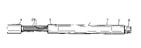
Figure 1 is a side elevational view of a pump in
accordance with the present invention in the retracted
position;
Figure 2 is a side elevational view of the pump of
Fig. 1 in the extended position;
Figures 3 and 4 are partly sectioned, side elevation
views of the pump of Figs. 1 and 2 on a larger scale, and in
the retracted and extended positions, respectively;
Figures 5 and 6 are schematic side elevation views
of a well string incorporating the pump of the present
invention.
- With reference to Figs. 1 to 4 of the drawings, the
basic elements of the pump include a tubular casing or barrel

1 335877
1, which carries a bottom sub 2, a splined housing or top
sleeve 3 and a splined mandrel or plunger 4. The tapered
upper end 6 of the bottom sub 2 is externally threaded for
attaching the sub to the internally threaded lower end 7 of
the barrel 1, and the lower end 8 of the sub 2 is externally
threaded for mounting the pump in a well string as described
hereinafter in greater detail. The tapered lower end 10 of
the sleeve 3 is externally threaded for connecting the sleeve
to the internally threaded upper end 11 of the barrel 1.
As best shown in Figs. 3 and 4, the bottom sub 2
carries a stationary or standing valve generally indicated at
12, and the plunger 4 carries a movable or moving valve
generally indicated at 14. The standing valve 12 is defined
by a lower retainer nut 15 in the form of a sleeve with an
externally threaded top end for retaining a pair of
longitudinally extending, tubular valve housings 17 and 18.
The valve housings 17 and 18 are interconnected end- to-end,
and are retained in the sub 2 by an annular top nut 19. An
O-ring 20 is provided between the upper valve housing 18 and
the sub 2 for sealing the valve housings 17 and 18 in the sub
2. Each housing 17 and 18 contains a valve seat 21 near the
bottom end thereof and a ball 22, which is longitudinally
movable in a valve chamber 24 in the housing 17 or 18.
The plunger 4 includes an elongated tubular body 25
with an enlarged head 27 for limiting downward movement of the
plunger in the barrel 1 and the sleeve 3. The head 27 is

1 335877
internally threaded for connecting the pump to well tubing 28
(Figs. 5 and 6) defining the upper end of the well string.
The well tubing 28 reciprocates the plunger 4 and carries
fluid to the wellhead. The body 25 of the plunger 4 includes
a plurality of longitudinally extending splines 29, for
sliding in corresponding grooves between splines on the inner
surface of the sleeve 3. The splines 29 permit longitudinal
movement while preventing rotation of the plunger 4.
The plunger 4 is sealed with respect to the barrel
1 by sealing rings 30 mounted in annular recesses in the inner
and outer surfaces of a sleeve or piston 32. The piston 32 is
retained on the bottom end of the plunger 4 by a piston nut
33, a jam nut 34 and set screws 35 (one shown).
As mentioned above, the plunger 4 carries a moving
valve 14. The valve 14 includes a pair of housings 37 and 38
(similar to the housings 17 and 18) which are interconnected
end-to-end, valve seats 40, and balls 41 longitudinally
movable in valve chambers 42. The housings 37 and 38 are
secured in the plunger 4 by a retainer nut 44 similar to the
nut 15, and a bottom nut 45 similar to the top nut 19 on the
standing valve 12. An O-ring 46 in the nut 44 seals the valve
14 with respect to the plunger 4.
In one use, the device described above is suspended
from well tubing 28 above a test tool. The test tool itself
does not form a part of the present invention, and accordingly
is not described in detail. The test tool includes an upper
sub 48,

1 335877
, ,
a main valve 49, an upper packer 50, a perforated anchor 52,
a lower sub 53, a recorder casing 54 and a lower packer 55,
which is optional. The packers 50 and 54 are used to create
hydraulic seals above and below a test area 57 after locating
the test area 57 by traversing the test tool through the well.
The seals prevent the flow of fluid above the packers 50 and
drilling fluids beneath the packer 55 across the packer seats,
i.e. the hydrostatic pressure of drilling fluids is removed
from the test area 57. With the test area sealed, the
perforated anchor 52 is opened to allow formation fluids to
flow into the anchor and consequently into the bottom end of
the sub 2. The fluid is removed via the pump of the present
invention.
In operation, the well tubing 28 is used to
reciprocate the plunger 4. During upward movement of the
plunger 4, the balls 22 in the standing valve 12 move upwardly
to open such valve permitting fluid to enter the chamber 60
(Fig. 3) produced between the bottom end of the plunger 4 and
the top end of the sub 2. At the same time, the balls 41 are
forced down against the seals 40 to close the moving valve 14.
When plunger movement is reversed, the balls 22 are forced
downwardly to the closed position against the seats 21 to
close the standing valve 12, and the balls 41 are forced
upwardly to open the moving valve 14, so that fluid is forced
upwardly into the tubing 28. Continued reciprocation of the
plunger 4 results in the pumping of formation fluid to the
wellhead.

~ 1 335877
The use of two seats 21 and 40, and two balls 22 and
41 in each valve 12 and 14 results in tight sealing and
consequently efficient pumping action. It will be noted that
the pump is structurally simple, and consequently easy to
produce.

Dessin représentatif
Une figure unique qui représente un dessin illustrant l'invention.
États administratifs

2024-08-01 : Dans le cadre de la transition vers les Brevets de nouvelle génération (BNG), la base de données sur les brevets canadiens (BDBC) contient désormais un Historique d'événement plus détaillé, qui reproduit le Journal des événements de notre nouvelle solution interne.

Veuillez noter que les événements débutant par « Inactive : » se réfèrent à des événements qui ne sont plus utilisés dans notre nouvelle solution interne.

Pour une meilleure compréhension de l'état de la demande ou brevet qui figure sur cette page, la rubrique Mise en garde , et les descriptions de Brevet , Historique d'événement , Taxes périodiques et Historique des paiements devraient être consultées.

Historique d'événement

Description Date
Exigences relatives à la révocation de la nomination d'un agent - jugée conforme 2020-04-22
Exigences relatives à la nomination d'un agent - jugée conforme 2020-04-22
Le délai pour l'annulation est expiré 2009-06-15
Inactive : Demande ad hoc documentée 2008-08-22
Lettre envoyée 2008-06-13
Inactive : CIB de MCD 2006-03-11
Accordé par délivrance 1995-06-13
Déclaration du statut de petite entité jugée conforme 1988-09-30

Historique d'abandonnement

Il n'y a pas d'historique d'abandonnement

Historique des taxes

Type de taxes Anniversaire Échéance Date payée
TM (catégorie 1, 2e anniv.) - petite 1997-06-13 1997-06-05
TM (catégorie 1, 3e anniv.) - petite 1998-06-15 1998-05-22
TM (catégorie 1, 4e anniv.) - petite 1999-06-14 1999-04-21
TM (catégorie 1, 5e anniv.) - petite 2000-06-13 2000-05-18
TM (catégorie 1, 6e anniv.) - petite 2001-06-13 2001-04-24
TM (catégorie 1, 7e anniv.) - petite 2002-06-13 2002-06-11
TM (catégorie 1, 8e anniv.) - petite 2003-06-13 2003-06-09
TM (catégorie 1, 9e anniv.) - petite 2004-06-14 2004-03-16
TM (catégorie 1, 10e anniv.) - petite 2005-06-13 2005-03-22
TM (catégorie 1, 11e anniv.) - petite 2006-06-13 2006-06-08
TM (catégorie 1, 12e anniv.) - petite 2007-06-13 2007-06-11
Titulaires au dossier

Les titulaires actuels et antérieures au dossier sont affichés en ordre alphabétique.

Titulaires actuels au dossier
KAARE IDLAND
Titulaires antérieures au dossier
S.O.
Les propriétaires antérieurs qui ne figurent pas dans la liste des « Propriétaires au dossier » apparaîtront dans d'autres documents au dossier.
Documents

Pour visionner les fichiers sélectionnés, entrer le code reCAPTCHA :


Pour visualiser une image, cliquer sur un lien dans la colonne description du document. Pour télécharger l'image (les images), cliquer l'une ou plusieurs cases à cocher dans la première colonne et ensuite cliquer sur le bouton "Télécharger sélection en format PDF (archive Zip)" ou le bouton "Télécharger sélection (en un fichier PDF fusionné)".

Liste des documents de brevet publiés et non publiés sur la BDBC .

Si vous avez des difficultés à accéder au contenu, veuillez communiquer avec le Centre de services à la clientèle au 1-866-997-1936, ou envoyer un courriel au Centre de service à la clientèle de l'OPIC.


Description du
Document 
Date
(aaaa-mm-jj) 
Nombre de pages   Taille de l'image (Ko) 
Abrégé 1995-06-13 1 22
Description 1995-06-13 7 236
Revendications 1995-06-13 2 70
Dessins 1995-06-13 4 131
Page couverture 1995-06-13 1 15
Dessin représentatif 2002-03-06 1 4
Avis concernant la taxe de maintien 2008-07-28 1 171
Demande de l'examinateur 1993-05-31 1 63
Demande de l'examinateur 1993-05-31 1 64
Demande de l'examinateur 1994-05-04 2 78
Demande de l'examinateur 1993-04-20 1 55
Courtoisie - Lettre du bureau 1993-05-21 1 58
Demande de l'examinateur 1992-12-15 1 69
Demande de l'examinateur 1990-12-31 1 53
Correspondance de la poursuite 1993-03-16 1 69
Correspondance de la poursuite 1994-10-13 1 34
Correspondance reliée au PCT 1995-03-14 1 32
Correspondance de la poursuite 1993-06-11 6 212
Correspondance de la poursuite 1994-08-04 4 122
Correspondance de la poursuite 1993-06-11 6 215
Correspondance de la poursuite 1991-01-07 1 26
Correspondance de la poursuite 1993-05-10 1 31
Courtoisie - Lettre du bureau 1993-05-20 1 29
Correspondance reliée au PCT 1993-03-11 2 63
Taxes 2003-06-09 1 24
Taxes 1998-05-22 1 33
Taxes 2002-06-11 1 25
Taxes 1997-06-05 1 42
Taxes 1999-04-21 1 32
Taxes 2004-03-16 1 27
Taxes 2005-03-22 1 26
Taxes 2006-06-08 1 24
Taxes 2007-06-11 1 24
Correspondance 2008-09-08 2 130