Note : Les descriptions sont présentées dans la langue officielle dans laquelle elles ont été soumises.
- I 3 3 7 2 5 4 27186-11
BACKGROUND AND SUMMARY OF THE INVENTION
The invention relates to a transfer device in a transfer
press or similar metal-forming machine.
Reference is made to the below listed related Canadian patent
applications:
(i) Canadian patent application Serial No. 612,777, filed
September 25, 1989, and
(ii) Canadian Patent application Serial No. 613,739, filed
September 27, 1989.
Transfer presses, bulky-part transfer presses, press
installations are metal-forming machines, in which sheet metal
parts are deformed by process steps, such as drawing and punching.
For this purpose, the presses have at least one slide, at which a
tool or a tool set (upper tool) is fastened which cooperates with
a tool or tool set (lower tool) in the press bed or on a sliding
table. The slides can be moved up and down by means of driving
devices of the press. Intermediate depositing devices are mounted
in areas between the frames leading to presses arranged behind
them, these areas being known as idle stages. The changing of the
tools or tool sets takes place utilizing of sliding tables which,
for this purpose, can be moved into and out of the press.
In United States patent Specification (US-PS) 4,625,540, a
press is disclosed having a device for transferring sheet metal
parts between working stages. This transfer device has two moving
1 337254
.~
rails on both sides of the slide and tools and extending in ~
conveying direction of the sheet metal parts. The moving rails
are supported on the press bed by supports. In addition, a plate
is provided for each moving rail, having rollers for placement on
the moving rails. Both plates are connected with one another by a
strut. Two transfer rods are disposed at the strut which extend
in parallel with respect to the moving rails. The transfer rods
are connected with a cam follower lever which receives a swinging
motion from a control cam. On the side of the drive, the control
cam is operatively connected with the main drive of the press.
The transfer rods are rigidly connected with one another by
traverses.
, ._ .
In guides of the transfer rods, cross bars are arranged which
by means of an additional drive can be moved relative to the
transfer rods. Vacuum suction devices are mounted at the cross
bars which, by means of the movement of the cross bars, can be
adjusted to the length of the sheet-metal parts. For the
deforming stage, the cross bars with the vacuum suction devices
can be adjusted into areas outside the slides and the tools. The
~r20 transfer rods can be lifted and lowered by means of lifting
devices which are not shown or explained in detail. The
setting-up of the vacuum suction device with respect to the
changed size of new sheet metal parts during the retrofitting of
the press must take place manually without the possibilities of
prior setting-up during the operating of the press
Accordingly, it is an object of the present invention to
provide a transfer device which permits a changing operation of
1 337254
27186-11
the holding devices to accommodate sheet metal parts of different
sizes. In particular, the changing operation of the holding
devices takes place automatically and at the same time with the
change of the tools via a sliding table arrangement. The changing
position of the holding devices or the devices carrying these
holding devices is achieved independently of the drive for the
transfer movements of the sheet metal parts.
Therefore, in accordance with a broad aspect, the present
invention provides a press including a working stage having at
least one slide, movable up and down by driving means, for the
deforming of sheet metal parts, sliding tables for changing tools
of the slide and transfer means movable in synchronism with
operation of the press having holding means for gripping and for
conveying sheet metal parts through the press, wherein the
transfer means has two moving rails, movable in lifting and
lowering directions which extend in a conveying direction of the
sheet metal parts on opposite sides of the slide and tools of the
slide and on which moving carriages are slidably arranged, wherein
at least two moving carriages located opposite one another on the
two moving rails are connected with one another by at least one
traverse at a coupling means arranged between each of the
carriages and associated traverse, and wherein the moving rails
are operatively connected with adjusting means fixed to the press
and have an adjusting member which can be moved substantially
horizontally and essentially transversely with respect to the
conveying direction of the sheet metal parts by means of the
- 1 337254
27186-ll
adjusting means for a movement of the moving rails between an
operative position and an uncoupled position.
According to another broad aspect of the invention, there is
provided a press including a work stage, having at least one
slide, which can be moved up and down by driving means, for
deforming sheet metal parts, sliding tables for facilitating a
changing of tools of the slide and transfer means movable in
synchronism with the press having holding means for gripping and
for conveying sheet metal parts through the press, wherein two
moving rails, extending through the press in a conveying direction
of the sheet metal parts, on both sides of the slide and
associated tools which are lifted and lowered by a first adjusting
means, wherein carriages are slidably disposed at the two moving
rails, in each case, two carriages being connected at the two
moving rails by at least one traverse and coupling means
respectively positioned between each of the carriages and
associated traverse, wherein by a second adjusting device the two
moving rails are moved between an initial height and second
position for lowering the traverses on supports at the sliding
table and wherein by additional adjusting means and deflecting
devices, the moving rails are adjusted from an operative position
into an uncoupled position for uncoupling the traverses from
associated carriages and back into the operative position.
Preferred embodiments of the present invention have a low-
mass construction which is advantageous. The driving devices and
the devices of the transfer device which transfer and deflect the
movements are assigned to the area (head area) of the press or
4a
- 1 337254
27186-11
presses, in which the driving devices for the slide or the slides
are also housed. The transfer device can be retrofitted in press
trains as well as in compact presses. Other advantages of
preferred embodiments of the present invention are the short
transfer movements of the carriages and their temporary waiting
position outside the working stages during the deforming phases.
In a particularly advantageous manner, the transfer device
according to preferred embodiments of the present invention can be
used in a new type of hybrid press installation with intermediate
depositing devices set up between two working stages (idle stages)
because the carriages, in pairs, can carry out different movements
if the drive is designed correspondingly. The sandwich
construction particularly of the carriages and the traverses not
only permits the fastest possible adaptation to new sheet metal
sizes and other sheet metal shapes, it also allows the simple
removal and replacement of components and subassemblies.
4b
,.~
1 337254
.i
Other objects, advantages and novel features of the present
invention will become apparent from the following detailed ..
description of the invention when considered in conjunction with --
the accompanying drawings.
BRIEF DESCRIPTION OF THE DRAWINGS
Figure 1 is a front view of a hybrid press installation, in
which frames located at the front of the installation are not
shown;
Figure 2 is a top view of the hybrid press installation
according to Figure 1, in which head pieces are not shown;
Figure 3 is an enlarged cutout of Figure 1 with the driving
devices for the transfer device according to one embodiment of the
present invention;
Figure 4 is a diagram of the movements of the carriages of
the transfer device generated by the driving devices shown in
Figure 3;
Figure 5 is an enlarged sectional view taken along line V-V
in Figure 3; and
Figure 6 is a sectional view taken along line VI-VI in Figure --
5. .
DETAILED DESCRIPTION OF THE DRAWINGS
In the Figures, a hybrid press installation is shown having a
head press 1, which may be a drawing press, and having additional
presses 2, of which at least one press may contain an additional
redrawing stage. The head pieces 7 of the individual presses 1, 2
,~-
1 337254
are supported on press beds 8 by means of frames 11, 12.
Reference number 10 indicates connecting rods which, for
example, by means of a crankshaft drive originating from a main
drive shaft 39, drive the slides 6 of the presses 1, 2 in an
upward and downward movement. The main shaft 39 is rotationally
moved by one or several motors by means of a clutch/brake unit
38.
By means of the paired sets of sliding tables 13 best seen in
Figure 2, tools or tool sets 14, 15 can be moved into the working
-~ 10 stages of the presses 1, 2 and can therefore be exchanged, in
which case the tool or the tool set 15 (lower tool part) for the
deforming operation of the presses remains on the respective
sliding table 13. The tool or the tool set 14 (upper tool part)
moves with the movement of the slide 6. A drawing apparatus 9 is
outlined for the head press 1.
The metal sheets 33 which are fed, for example, to the head
press 1 by means of a feeding device 3 are moved from one working
stage to the next working stage by means of a transfer device 5
and guided to a removal station 4. Sheet metal parts of different
20 sizes, which are to be conveyed and worked, as shown in Figure 2, .
have the reference number 33' and can also be accommodated by the
transfer device 5. The direction and the level of the sheet metal
conveyance has the reference number 32.
Intermediate depositing devices 17 for the depositing of the
sheet metal parts 33 are set up in the idle-stage areas 88 between
the working stages. Supports 35 are provided at the sliding -
tables 13 for receiving the traverses 34 of the transfer device 5
~- .
1 337254
as will be described in the following.
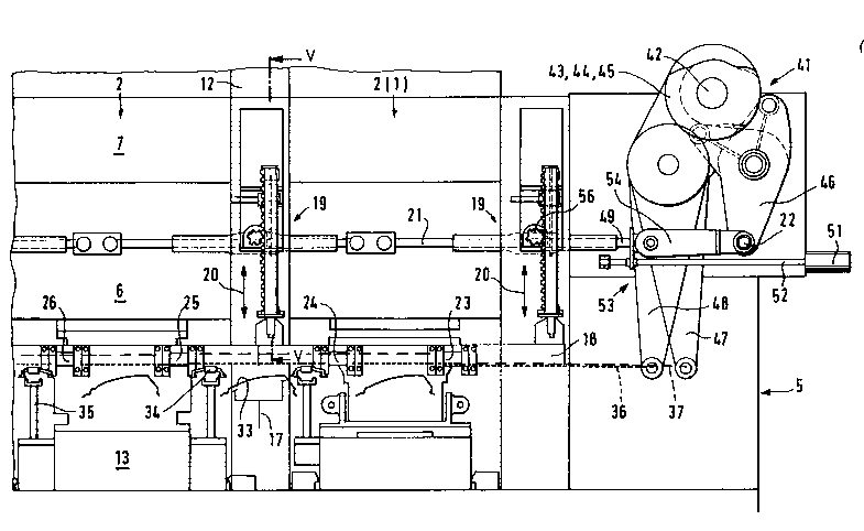
The transfer device 5 shown in Flgures 1, 2 and 3 has two
moving rails 18, one of which, as viewed in Figure 1, is arranged
behind the slides 6 with the upper tool parts 14, and the second
moving rail is arranged in front of the slides 6 with the upper
tool parts 14. The moving rails 18 extend in the longitudinal
direction of the shown hybrid press installation. The moving
rails 18 can be lifted and lowered (double arrow 20 in Figure 1)
by adjusting devices or the like, such as air cylinders, or, as
shown, by means of deflection gears 19. The deflection gears 19
will be explained in detail with respect to Figures 5 and 6.
The deflection gears 19 of the rear frame side B of the
hybrid press installation and those of the front frame side C are
each connected by means of one lifting rod linkage 21
respectively, at pivotal points 22, with one cam follower lever 46
respectively for each frame side of a cam disk arrangement which,
as a whole, has the reference number 41. As outlined in Figures 1
and 2 and shown in detail in Figures 3 and 4, carriages 23 to 31
of the transfer device 5 are disposed at each of the moving rails
,~
18.
Carriages 23, 25, 27, 29 and 31, by means of a conveying rod
system 37, are connected with one another and with a cam follower -
lever 47. Carriages 24, 26, 28 and 30, by means of a conveying
rod system 36, are connected with one another and with a cam
follower lever 48. Carriages 23 to 31, which are located opposite
one another on the spaced moving rails 18, are connected with one
another by means of traverses 34. Suction devices 40 or similar
., ~ ~1-
-
1 337254
holding devices are arranged at the traverses 34 for the gripping
of the sheet metal parts 33, 33' and for conveying them through
the hybrid press installation. The conveying rod system 36, 37
may be arranged on both sides of the moving rails 18, as seen in
Figure 2, or on one side of the moving rails.
The cam disk arrangement 41, as shown in detail in Figures 2
and 3, comprises a cam disk shaft 42. The cam disk shaft 42 is
rotated by the main shaft 39 by means of deflecting or transfer
gears. These devices, which are known in metal-forming machines,
are not shown. For each frame side B, C of the press
installation, one cam disk 44 for the movement of one of the two
cam follower levers 46, one cam disk 45 for the movement of one of
the two cam follower levers 47 and one cam disk 43 for the
movement of one of the two cam follower levers 48 is non-rotatably
arranged on the cam disk shaft 42. The cam disks 44, 43, 45 may
be double cam disks for generating a controlled motion in the
lifting and lowering movements of the moving rails 18 and the
transfer movements of the carriages 23 to 31.
As shown in Figure 3, each of the lifting rod linkages 21, in
20 its initial position, can be changed by a lowering movement, of an -
adjusting drive as will be described below in order to achieve an
additional lowered position by a movement 94 as shown in Figure 4
for the moving rails 18 which cannot be provided by the cam disks
44. This lowered position is required for the depositing of the
traverses 34 on the supports 35 of the sliding tables 13 during
the tool change and the changing of the holding devices 40. -
For this purpose, each adjusting drive has an adjusting motor
-
'~g
1 337254
51 which drives.a spindle 52. The rotating movement of the
-spindle 52, by means of a pair of toothed gears 53, i.s transmitted
to a second spindle 49. In the cover plate 54, a moving thread
(nut) is inserted which interacts with the spindle 49 and thus,
during the rotation of the spindle 49, causes a change or shifting
of the length of the lifting rod linkage 21.
The cam disks 43, 45 for the movement of the carriages 23 to
31 are designed such in their curved paths tapped by the cam
follower levers 47, 48 that the first carriage 23 and each
~~ 10 next-plus-one carriage 25, 27, 29, 31, corresponding to Figure 4,
carries out a transfer movement 82 in transfer direction 32 as
seen in Figure 4 from a working stage 86 into an idle stage 88
having the intermediate storage device 17 for supporting a sheet
metal part 33 and a return movement 84 into working stage 86
which, at an intermediate position 89 between working stage 86 and
idle stage 88, is interrupted during the time of the deformation
or working of the sheet metal part 33.
The second carriage 24 and each next-plus-one carriage 26,
28, 30 connected with it simultaneously carries out a transfer
movement 83 in transfer direction 32 as shown in Figure 4 from an
idle stage 88 having the intermediate depositing device 17 for
supporting a sheet metal part 33 into a working station 87 and a
return movement 85 into the idle stage 88 which, at an
intermediate position 89 between the idle stage 88 and the working
stage 87, is temporarily interrupted during the deforming or
working of the sheet metal part 33. The working stages are
characterized by the tools 14, 15. The vertically extending
.. ~ q
1 337254
motional parts of the curves 82, 83, 84, 85 shown in Figure 4 are
caused by means of the cam disks 44 which are moved .synchronously
with the cam disks 43, 45. -
The sectional view of Figure 5 and partially also the
sectional view of Figure 6 shows the area of one of the frames 12
of the hybrid press installation which has a deflecting gear 19.
The lifting rod linkage 21, in Figure 5, extends vertically with
respect to the plane of the drawing. The movement of the lifting
rod linkage 21, by means of a toothing and engagement with a spur
wheel 56 and a rotating shaft 57, is transmitted to a second spur
wheel 58. The second spur wheel 58 interacts with a toothed rack
59. The end areas of the toothed rack 59 are firmly connected
with an upper flange bushing 61 and a lower flange bushing 62. The
upper flange bushing 61 forms a running surface 65 for a lifting
pipe 64. The upper flange bushing 61 also interacts with a cover
plate 63 which is screwed on an upper collar of the lifting pipe
64. This connection permits a pivotal movement of the lifting
pipe 64 about pivot point A as shown in Figure 6.
The pivotal movement of the lifting pipe 64 is caused by
means of an adjusting device 76, such as a pressure cylinder
which, by means of a bearing block 77, is fixedly mounted at the
frame 12. The bearing block 77 permits a swivelling motion of the
adjusting device 76. At reference number 78, the adjusting device
76 is pivotally connected to a ring bush 75. The ring bush 75,
for example, by means of guide bolts, engages in longitudinal
grooves 90 of the lifting pipe 64 in order to permit the lifting
and lowering movement 20 of the lifting pipe 64 required for the
- /o
~ t 337254
moving rails 18-and permit the pivotal movement of the lifting
pipe 64.
At its lower end part, the lifting pipe 64 carries a flange
66 with a flanged bush 67. The flanged bush 67 is surrounded by a
bearing bush 73 and a support bush 72 for forming a pivot bearing
between the lifting pipe 64 and a support 71. The support bush 72
is held in a support 71 by means of a screwed connection 74. A
flange bushing 68 is placed on the lower end of the support bush
72. A screw device 69 is guided through the flange bushing 68 in
order to fasten the support 71 to the lifting pipe 64. The moving
rail 18 is rigidly connected with the support 71. The moving rail
18 has two rails or rail pairs 79 on which rollers 80 of carriages
23 to 31 roll, in this case, the rollers 80 of carriage 25. The
conveying rod system which is connected to the housing 81 of the
carriage 25 has the reference number 37. As a result of the
rotating movement of the lifting pipe 64 by means of adjusting
devices 76, an adjustment of the moving rails 18 is possible from
the inside to the outside as shown in Figure 6 by arrow 91, for
example, for the uncoupling of the traverses 34 from the moving
carriage 25, or from the outside to the inside as shown in Figure
6 by arrow 92, for the corresponding coupling.
Figure 6 also shows the positions 64' for the operative
position and 64'' for the uncoupling and coupling position of the
traverses 34 caused by adjusting devices 76.
Reference number 93 indicates coupling areas or couplings for
the detaching of the traverses 34 from the carriages, in this -
case, carriages 24, 25, or the coupling to these carriages as a
~ / I
1 337254
result of a movement of the moving rails 18 in one of the
directions of arrows 91, 92. In the operative position, the rails
79 at the moving rails 18 are located in the center with respect
to the lifting pipe 64.
Although the present invention has been described and
illustrated in detail, it is to be clearly understood that the
same is by way of illustration and example only, and is not to be
taken by way of limitation. The spirit and scope of the present
invention are to be limited only by the terms of the appended
~ 10 claims.
; 20