Note : Les descriptions sont présentées dans la langue officielle dans laquelle elles ont été soumises.
-
1 33803~
Seal for Magnetisable Shaft
The present invention relates to a seal for a magnetisable shaft.
Such a seal is known from DE-PS 33 05 649, where the conical surface
which defines the sealing surface proximate to the space to be sealed axially
subtends a steeper angle with the axis of the shaft than the opposing conical
surface remote from the sealed space. This results in a permanent throwing
action towards the sealed space. Althou~h this is effective for sealing the
medium contained, it also causes a constant suction effect in the closely
adjacent region outside the seal. Foreign bodies can thus enter the sealing
gap entrained in the induced air and cause wear and premature failure of the
seal. In addition, a superimposed seal is affected by abrasives to a very
great extent. Its service life, and that of the whole seal is thus less than
satisfactory.
Ferrofluid seals are known and are described, for example, in DE-OS
35 01 937. They make use of a permanent magnet surrounding but spaced from
the shaft to be sealed with a ferrofluid in the gap so formed. Such seals are
used as main seals, and their ability to withstand pressure makes their use
possible when one side is subjected to atmospheric pressure while the other is
acted upon by a partial vacuum.
It is an object of the present invention to so improve a magnetisable
shaft seal of the type described that better prOtectiQn for the seal lip is
provided against the effects of foreign bodies without~ detriment to the
sealing effect.
It has been found that conventional shaft seals with a seal lip of
polymer material using a throwing action in the direction of the space to be
sealed, exceed the pressure resistance of conventional ferrofluid seals by a
factor of 1.5 to 3Ø Ferrofluid seals may also be used in the present
apparatus, but as a supplementary seal for the sealing lip, with an annular
buffer space between the ferrofluid seal and the part of the seal lip which
lies on the surface of the shaft to be sealed.
When the shaft is rotating, a vacuum is created in this space because
of the throwing action effective in the area of the seal lip. From time to
time this vacuum exceeds the pressure resistance of the ferrofluid seal
PAT 12855-1
A -1-
1 338û3~
resulting in a brief liftin~ or breakin~ of the ferrofluid away from the
surface of the shaft.
Air at atmospheric pressure can thus flow into the buffer space and
thereby relieve the vacuum in it before the liquid ferrofluid once a~ain forms
a~ainst the whole outside circumference of the shaft. The buffer space is
then again axially sealed to the outside, until such time as the vacuum once
more exceeds the pressure resistance of the supplementary seal, thereby
causin~ a new temporary liftin~ of the ferrofluid.
The time within which the liftin~ is completed is of the order of a
few milliseconds, so that particles of dust suspended in the air, because of
their inertia, cannot follow the movement of the air drawn in. In the
prototype, even after a protracted period of operation, and under severe
operatin~ conditions, it was practically impossible to detect the presence of
any foreign bodies in the buffer space, which had ori~inated in the outside
air.
It may be si~nificant that the ~eometric extent of that part of the
rin~ of ferrofluid liquid involved in the breakin~ or liftin~ process is
confined to a very small se~ment and is immediately adjacent the surface of
the rotatin~ shaft. The re~ion may be relatively free of dust for reasons of
flow technology and the se~ment may also desi~nate the location on the
circumference of the shaft at which its distance from the inner side of the
permanent ma~net has reached a relatively lar~e value.
The annular ma~net can be secured to the housing which supports the
seal lip, for example, by means of an attached clampin~ system. The housin~
and the seal lip can be appropriately confi~ured to correspond to that of any
other known shaft seal.
In another configuration, there is provision made so that the annular
ma~net is secured to the seal lip, but movable with it relative to the
housin~. This ~ives ~ood radial ~uidance of the seal lip with respect to the
surface of the shaft, which in turn results in reduction of wear caused by
relative displacements in the radial direction durin~ operation.
The gap between the annular ma~net and the surface of the shaft
within which the ferrofluid is contained, should be of an axial len~th ~reater
than its radial width. Even should there be some loss of some of the
ferrofluid over time, there will then be no substantial reduction of the total
PAT 12855-1
A -2-
1 338~ 7
three to six times greater than the radial width of the gap, in light of the
factors set out above.
It can be useful, as a function of the spatial conditions imposed by
special applications, that the annular magnet be fitted with a pole shoe on
5 the side that is proximate to the shaft. The magnetic field that retains the
ferrofluid can thus be associated with and brought close to the surface of the
shaft in a particularly favourable way.
The annular magnet and/or the pole shoe can also be of a magnetisable
plastic. In addition to improving the corrosion resistance, this reduces
10 weight, which can be advantageous for specific applications.
The new seal described can be produced relatively simply, and known
individual parts can be used to do this. The service life is improved over
known seals and contamination by dust entrained in outside air adjacent the
seal is reduced. This is particularly important, for example, in use of the
15 seal in the medical or electromechanical fields.
More particularly in accordance with the invention there is provided,
a seal for a magnetisable shaft having a longitudinal axis and which comprises,
a housing,
a radially displaceable seal lip of elastomeric material mounted in
20 the housing and having a sealing surface for engaging the shaft and defined
between two conical end surfaces on opposite sides of said sealing surface,
the conically inclined end surface facing away from a space to be
sealed subtending a smaller angle with the longitudinal axis than the other
opposite end surface,
a supplementary seal beyond said end surface facing away from the
sealed space,
said supplementary seal comprising:
an annular magnet spaced from and surrounding the shaft and defining
a magnetic circuit gap with said shaft,
and a ferrofluid in the gap.
Embodiments of the invention will now be described with reference to the
accompanying drawings, wherein:
Figures 1 to 3 are side partly sectioned views of shafts and seals,
each illustrating a separate embodiment of the invention.
1 338037
each illustrating a separate embodiment of the invention.
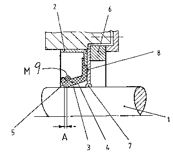
The embodiment shown in Figure 1 comprises a housing 2 of sheet steel
of angle profile and a rubber seal lip 3 on a radially inwardly directed arm.
The arm is molded on directly, bonded in place and consolidated by a
vulcanizing process.
Production requirements give the seal lip 3 a sealing edge formed by
two intersecting conical surfaces 4 and 5. In the operational state shown,
surfaces 4 and 5 are pressed under elastic tension against the surface of the
shaft 1 to be sealed by a coil spring 9 installed on the outside; the sealing
edge thus undergoes elastic deformation and comes into contact with the
surface of the shaft 1 in zone A. This zone A is defined on the side of the
sealed space H by the conical surface 5 which subtends a greater conical angle
with the axis of the shaft 1 than does the conical surface 4 which faces in
the axially opposite direction. Thus when the shaft 1 is rotating, under
normal operating conditions there is a throwing action for liquid on the shaft
effective in the direction of the sealed space M.
On the side of the housing 2 remote from the sealed space M is an
annular magnet 6 fitted with an inwardly extending ann--lar pole shoe 8. The
pole shoe 8 is closely adjacent to the surface of the shaft 1 to be sealed,
forming the gap 7. The ferrofluid is contained in this gap, and is prevented
from escaping by the flux from the permanent magnet 6 which develops in the
pole shoe 8 and shaft 1.
The seal just described functions as follows:
When the shaft is rotating there is a constant throwing effect, which
acts in the direction of the sealed space M in the region of the sealing edge
of the seal lip 3. This results in the generation of an increasing vacuum in
the buffer space between the seal lip 3 and the ferrofluid seal, and
ultimately this vacuum becomes high enough that the ring of liquid formed by
the ferrofluid between the inner side of the pole shoe 8 and the outer side of
the shaft 1 lifts briefly away from the surface of the shaft, at one point on
the periphery such that air at atmospheric pressure flows into the buffer
space. The partial vacuum that existed in the buffer space is thus relieved
and immediately thereafter renewed liquid contact is established between the
ring of ferrofluid and the surface of the shaft 1. Thus, the operating cycle
can recommence.
PAT 12855-1
A -4-
1 338037
The embodiment of the seal shown in Fi~ure 2 differs from the
embodiment just described in that the annular magnet 6' is connected to the
lip ring 3' in one piece and is associated with the surface of the shaft 1 to
be sealed in the same manner as the seal lip of the lip ring 3 of Figure 1.
Between the lip ring 3' and the arm of the profile of the housing 2' directed
radially inwards, is a membrane-like transition piece 10 of Z-profile with
thin hinges in the areas of the corners, connecting the stiffer areas of the
profile. In addition to good axial guidance of the seal lip, this also
ensures improved relative mobility in the radial direction.
The lip ring 3' has a seal edge which is shaped and deformed by use
in a particular application in the same way as that in the embodiment as in
Figure 1. However, the lip ring 3' has the annular magnet 6' in the area
remote from the outside air at an axial distance from the seal edge, and
spaced from the surface of the shaft 1 to be sealed. Ferrofluid is arranged
in the gap 7' formed and acts as a supplementary seal under normal operating
conditions, in the same way as has been described in the embodiment of
Figure 1. In addition, the presence of the ferrofluid, which is a liquid, in
the gap 7' ensures that this gap is held at a uniform radial width round the
whole periphery of the shaft 1. Thus, the lip ring 3, mounted to the magnet
6', is oriented to the surface of the shaft 1 in a constant manner, which is a
particular advantage for achieving good sealing effect under operating
conditions as the shaft undergoes radial displacements. Any temporary problem
in the alignment and association of the sealing edge to the shaft in such
instances is thus relieved.
The embodiment shown in Figure 3 differs from those earlier described
in that the annular magnet 6" is secured directly within a recess in housing
2". Its inside periphery is separated by a very small radial clearance from
the surface of the shaft 1 to be sealed, and the ferrofluid is contained
within the gap 7". On the side proximate to the sealed space M, a PFTE seal
disk 3" is vulcanized onto the arm of the profile of the housing 2". The disk
3" is curved inwardly in the direction of the sealed space M and its inner
periphery lies on the surface of the shaft 1 over the axially extending zone
A'. The surface 4' adjacent to the sealing zone A' but on the side remote
from the sealed space H, rises at a smaller angle away from the shaft than
PAT 12855-1
-5-
1 338037
-
does the opposite end surface 5'. The throwin~ action effective in the
direction of the space M to be sealed under normal operating conditions is
thus similar to that in the embodiments described earlier. The functioning of
the supplementary seal is also similar.
PAT 12855-1
-6-
A