Sélection de la langue

Search

Sommaire du brevet 1338211 

Énoncé de désistement de responsabilité concernant l'information provenant de tiers

Une partie des informations de ce site Web a été fournie par des sources externes. Le gouvernement du Canada n'assume aucune responsabilité concernant la précision, l'actualité ou la fiabilité des informations fournies par les sources externes. Les utilisateurs qui désirent employer cette information devraient consulter directement la source des informations. Le contenu fourni par les sources externes n'est pas assujetti aux exigences sur les langues officielles, la protection des renseignements personnels et l'accessibilité.

Disponibilité de l'Abrégé et des Revendications

L'apparition de différences dans le texte et l'image des Revendications et de l'Abrégé dépend du moment auquel le document est publié. Les textes des Revendications et de l'Abrégé sont affichés :

  • lorsque la demande peut être examinée par le public;
  • lorsque le brevet est émis (délivrance).
(12) Brevet: (11) CA 1338211
(21) Numéro de la demande: 1338211
(54) Titre français: RECIPIENT-DISTRIBUTEUR DE LIQUIDE
(54) Titre anglais: CONTAINER AND LIQUID DISPENSER
Statut: Périmé et au-delà du délai pour l’annulation
Données bibliographiques
(51) Classification internationale des brevets (CIB):
  • B67D 03/00 (2006.01)
(72) Inventeurs :
  • LARSON, RAYMOND L. (Etats-Unis d'Amérique)
(73) Titulaires :
  • RAYMOND L. LARSON
(71) Demandeurs :
(74) Agent:
(74) Co-agent:
(45) Délivré: 1996-04-02
(22) Date de dépôt: 1987-08-18
Licence disponible: S.O.
Cédé au domaine public: S.O.
(25) Langue des documents déposés: Anglais

Traité de coopération en matière de brevets (PCT): Non

(30) Données de priorité de la demande:
Numéro de la demande Pays / territoire Date
055,440 (Etats-Unis d'Amérique) 1987-05-29

Abrégés

Abrégé anglais


A flexible and disposable water bottle adapted to be
used with water coolers and dispensers has a generally
cylindrical body joined to a conical neck and a flat base. A
removable cap threaded on the upper end of the neck closes the
opening into the chamber of the bottle. The neck has an
inwardly directed shoulder engageable with an annular seal
mounted on a dispenser when the bottle is in the inverted
installed position. The shoulder is positioned in annular
surface sealing engagement with the seal. The body and base
of the bottle have normally disposed handles to facilitate the
mounting of the bottle on the dispenser.

Revendications

Note : Les revendications sont présentées dans la langue officielle dans laquelle elles ont été soumises.


THE EMBODIMENTS OF THE INVENTION IN WHICH AN
EXCLUSIVE PROPERTY OR PRIVILEGE IS CLAIMED ARE DEFINED AS
FOLLOWS:
1. A container for storing a liquid and a liquid
dispenser accommodating said container comprising:
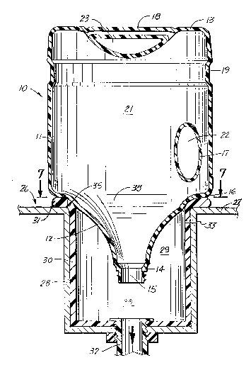
a liquid dispenser having a top wall with an
opening,
wall means providing a well below the top wall for
accommodating a liquid, annular seal means mounted on said
top wall surrounding said opening, and means operable to
allow liquid to flow from said well; container means for
storing said liquid, said container means having a
cylindrical side wall, a base joined to the side wall, and a
neck joined to the side wall, said neck having an opening
allowing the liquid in the container means to flow out of
the container means into the well, said neck having annular
shoulder means located in surface engagement with the
annular seal means when the container means is located on
said dispenser and the neck projects into the well whereby
the liquid in the container means flows into the well, said
side wall having a first generally upright handle adapted to
be gripped by one hand of a person, and said base having a
second handle adapted to be gripped by the other hand of a
person whereby the container means can be lifted and
inverted in operative relationship with said dispenser
means, said first handle being in transverse alignment with
said wall, said side wall having a first recess means
extended under the first handle, and said base having a
- 13 -

second recess means extended over the second handle, said
second handle being in transverse alignment with said base
so as to not interfere with resting of the container means
on a flat surface.
2. The structure of Claim 1 wherein: said side
wall has at least one groove located between the first and
second handles, said groove extended around said side wall.
3. The structure of Claim 1 wherein: said side
wall has a plurality of grooves located between the first
and second handles, said plurality of grooves extending
around said side wall.
4. The structure of Claim 1 wherein: said side
wall has a plurality of arcuate grooves opposite the first
handle.
5. The structure of Claim 4 wherein: said side
wall includes at least one groove located between the first
and second handles, said at least one groove extending
around said side wall.
6. The structure of Claim 1 wherein: said neck
has a generally conical shape, said shoulder joining said
neck to said side wall.
7. The structure of Claim 1 wherein: said side
wall base and neck are made of plastic material, said
shoulder being concave to conform to the configuration of
the annular seal means.
8. The structure of Claim 1 wherein: said
container means has a longitudinal axis, and said first and
second handles are normally disposed relative to each other
- 14 -

and located in a plane extended through the longitudinal
axis of the container means.
9. The structure of Claim 8 wherein: said
opening of said neck is located along said longitudinal
axis .
10. A container for storing a liquid and a liquid
dispenser accommodating said container comprising: a liquid
dispenser having a wall with an opening, means providing a
well located adjacent said wall for accommodating a liquid,
seal means mounted on said wall surrounding said opening,
and means operable to allow liquid to flow from said well;
container means for storing said liquid, said container
means having curved circumferential wall means surrounding a
chamber for accommodating said liquid, a base joined to the
wall means, and a neck joined to the wall means, said neck
having an opening allowing the liquid in the container to
flow out of the container means into the well, said neck
having shoulder means located in engagement with the seal
means when the container means is mounted on said dispenser
and the neck projects into the well whereby liquid in the
container means flows into the well, said wall means having
a relieved portion extending substantially chordally of said
circumferential wall means along its vertical height on a
portion of the wall means, said relieved portion of the side
wall having a generally U-shaped concave configuration
radially inwardly of the circumference of the wall means and
an integral handle extended vertically along said wall
means, the outer portion of said handle being disposed at
- 15 -

said circumference of the wall means and the inner portion
of which is spaced from the relieved portion of the side of
the wall means, said handle having opposite ends integrally
connected to the wall means through concavely curved
portions joined to opposite parts of the relieved portion of
the wall means, said handle means to be gripped by a hand of
a person whereby the container means can be moved to
assembled relation with the dispenser means with the
shoulder means in engagement with the seal means.
11. The structure of Claim 10 wherein: said wall
means includes at least one groove located adjacent said
handle means, said groove extending around said wall means.
12. The structure of Claim 10 wherein: said wall
means has a plurality of grooves located adjacent said
handle means, said plurality of grooves extending around
said wall means.
13. The structure of Claim 12 wherein: said wall
means has a plurality of arcuate grooves opposite the handle
means.
14. The structure of Claim 10 wherein: said wall
means, base and neck are made of plastic material, said
shoulder being concave to conform to the configuration of
the seal means.
15. The structure of Claim 10 wherein: said
handle means includes a handle joined to the base adapted to
be gripped by a hand of a person.
16. The structure of Claim 15 wherein: said base
has a recess extended over the handle means.
- 16 -

17. The structure of Claim 10 wherein: said
sidewall includes at least one groove having a
circumferential extent greater than 180 degrees.
18. A container for storing a liquid usable with a
liquid dispenser wherein the container is inverted in
associating the same with the dispenser, comprising:
(a) a substantially cylindrical body portion
having a cylindrical sidewall,
i) said sidewall having a plurality of
reinforcing grooves extending over a major portion of said
sidewall,
ii) said sidewall further having a relieved
portion extending substantially chordally of said
cylindrical body along its vertical height on a portion of
said sidewall, said relieved portion being spaced from said
grooves,
(iii) said relieved portion of the sidewall
having a generally U-shaped concave configuration radially
inwardly of the body portion circumference,
(iv) and further including an integral handle
extending vertically along said sidewall, the outer portion
of said handle being disposed at said circumference and the
inner portion of which is spaced from the relieved portion
of the sidewall, said handle having opposite ends integrally
connected to said sidewall through concavely curved portions
joined to opposite parts of the relieved portion of the
sidewall,
- 17 -

(b) a bottom wall including substantially planar
portions to permit the container to rest stably thereon,
said bottom wall having a convex peripheral edge portion
merging into said sidewall about the entire periphery of the
sidewall in a smooth radius to integrally join said bottom
wall with said sidewall,
(c) a throat portion extending upwardly from the
upper end of said sidewall, said sidewall having a convex
peripheral edge portion at the upper end thereof merging
into the throat portion about the entire periphery of the
throat portion said peripheral edge portion having a
continuous smooth radius about the entire periphery, said
throat portion being of smoothly curved concave
configuration and of decreasing diameter upwardly from said
sidewall providing, a continuous curved surface for
supporting said container when inverted in use, said
cylindrical, grooved, radiused, convex peripheral edge, and
concavely curved surfaces and portions of said container
provide substantial strength and reinforcement to said
plastic bottle during shipping, storage, and handling
thereof prior to inverting the same for dispensing, and
during the dispensing of liquid herefrom, while said handle
facilitates manipulation of the container for inverted
dispensing; and,
(d) a terminal neck extending upwardly from said
throat portion for receiving closure means when said
container is filled with liquid.
- 18 -

19. The container of Claim 18 wherein: said
sidewall, bottom wall, peripheral edge portions and throat
portion has substantially uniform thickness throughout the
length thereof.
20. The container of Claim 19 wherein: the
reinforcing grooves include circumferentially extending
substantially parallel grooves.
21. A container for storing a liquid usable with
a liquid dispenser wherein the container is inverted in
associating the same with the dispenser, comprising:
(a) a substantially cylindrical body portion
having a cylindrical sidewall,
(i) said sidewall having a plurality of
reinforcing grooves extending over a major portion of said
sidewall,
(ii) said sidewall further having a relieved
portion extending substantially chordally of said
cylindrical body along its vertical height on a portion of
said sidewall, said relieved portion being spaced from said
grooves,
(iii) said relieved portion of the sidewall
having a generally U-shaped concave configuration radially
inwardly of the body portion circumference,
(iv) and further including an integral side
handle extending vertically along said sidewall, the outer
portion of said handle being disposed at said circumference
and the inner portion of which is spaced from the relieved
portion of the sidewall, said handle having opposite ends
- 19 -

integrally connected to said sidewall through concavely
curved portions joined to opposite parts of the relieved
portion of the sidewall,
(b) a bottom wall including substantially planar
portions to permit the container to rest stably thereon,
said bottom wall having a convex peripheral edge portion
merging into said sidewall about the entire periphery of the
sidewall in a smooth radius to integrally join said bottom
wall with said sidewall, said bottom wall includes a
relieved portion extending substantially diametrically of
said bottom wall, said relieved portion of the bottom wall
having a generally U-shaped concave configuration axially
inwardly of the said planar portions of the bottom wall, and
further including an integral bottom handle extending
transversely of said relieved portion of the bottom wall,
the outer portion of said bottom handle being disposed
substantially coplanar with said planar bottom wall portions
and the inner portion of which is integrally connected to
said bottom wall through concavely curved portions to
further rigidifying said container and facilitating
manipulation thereof, said side handle and bottom handle
being located in a vertical plane passing through the
container,
(c) a throat portion extending upwardly from the
upper end of said sidewall, said sidewall having a convex
peripheral edge portion at the upper end thereof merging
into the throat portion about the entire periphery of the
throat portion a smooth radius about the entire periphery,
- 20 -

said throat portion being of smoothly curved concave
configuration and of decreasing diameter upwardly from said
sidewall providing, a continuous curved surface for
supporting said container when inverted in use, said
cylindrical, grooved, radiused, convex peripheral edge, and
concavely curved surfaces and portions of said container
provide substantial strength and reinforcement to said
plastic bottle during shipping, storage, and handling
thereof prior to inverting the same for dispensing, and
during the dispensing of liquid herefrom, while said handle
facilitates manipulation of the container for inverted
dispensing; and,
(d) a terminal neck extending upwardly from said
throat portion for receiving closure means when said
container is filled with liquid.
22. The container of Claim 21 wherein: said body
portion handle and said bottom handle are disposed at right
angles to each other.
23. The container of Claim 21 wherein: said
sidewall, bottom wall, peripheral edge portions and throat
portion has substantially uniform thickness throughout the
length thereof.
24. The container of Claim 21 wherein: the
reinforcing grooves include circumferentially extending
substantially parallel grooves.
25. The container for storing a liquid usable
with a liquid dispenser wherein the container is inverted in
- 21 -

associating the same with the dispenser, comprising: a one-
piece blow-molded plastic bottle having
(a) a substantially cylindrical body portion
having a cylindrical sidewall,
(i) said sidewall further having a relieved
portion extending substantially chordally of said
cylindrical body along its vertical height on a portion of
said sidewall,
(ii) said relieved portion of the sidewall
having a generally U-shaped concave configuration radially
inwardly of the body portion circumference,
(iii) and further including an integral
handle extending vertically along said sidewall, the outer
portion of said handle being disposed at said circumference
and the inner portion of which is spaced from the relieved
portion of the sidewall, said handle having opposite ends
integrally connected to said sidewall through concavely
curved portions joined to opposite parts of the relieved
portion of the sidewall;
(b) a bottom wall including substantially planar
portions to permit the container to rest stably thereon,
said bottom wall having a convex peripheral edge portion
merging into said sidewall about the entire periphery of the
sidewall in a smooth radius to integrally join said bottom
wall with said sidewall,
(c) a throat portion extending upwardly from the
upper end of said sidewall, said sidewall having a convex
peripheral edge portion at the upper end thereof merging
- 22 -

into the throat portion about the entire periphery of the
throat portion in a smooth radius about the entire
periphery, said throat portion being of smoothly curved
concave configuration and of decreasing diameter upwardly
from said sidewall providing, a continuous curved surface
for supporting said container when inverted in use, said
cylindrical, grooved, radiused, convex peripheral edge, and
concavely curved surfaces and portions of said container
provide substantial strength and reinforcement to said
plastic bottle during shipping, storage, and handling
thereof prior to inverting the same for dispensing, and
during the dispensing of liquid herefrom while said handle
facilitates manipulation of the container for inverted
dispensing; and,
(d) a terminal neck extending upwardly from said
throat portion for receiving closure means when said
container is filled with liquid.
26. The container of Claim 25 wherein: said
sidewall, bottom wall, peripheral edge portions and throat
portion has substantially uniform thickness throughout the
length thereof.
27. A container for storing a liquid usable with
a liquid dispenser wherein the container is inverted in
associating the same with the dispenser, comprising:
(a) a substantially cylindrical body portion
having a generally circumferential sidewall,
i) said sidewall having a plurality of reinforcing
grooves extending over a major portion of said sidewall,
- 23 -

ii) said sidewall further having a relieved
portion extending substantially chordally of said
cylindrical body along its vertical height on a portion of
said sidewall, said relieved portion being spaced from said
grooves,
iii) said relieved portion of the sidewall having
a generally U-shaped concave configuration radially inwardly
of the body portion circumference,
iv) and further including an integral side handle
extending vertically along said sidewall, the outer portion
of said handle being disposed at said circumference and the
inner portion of which is spaced from the relieved portion
of the sidewall, said handle having opposite ends integrally
connected so said sidewall through concavely curved portions
joined to opposite parts of the relieved portion of the
sidewall,
(b) a bottom wall including substantially planar
portions to permit the container to rest stably thereon,
said bottom wall having a convex peripheral edge portion
merging into said sidewall about the entire periphery of the
sidewall in a smooth radius to integrally join said bottom
wall with said sidewall, said bottom wall includes a
relieved portion extending substantially diametrically of
said bottom wall, said relieved portion of the bottom wall
having a generally U-shaped concave configuration axially
inwardly of the said planar portion of the bottom wall, and
further including an integral bottom handle extending
transversely of said relieved portion of the bottom wall,
- 24 -

the outer portion of said bottom handle being disposed
substantially coplanar with said planar bottom wall portions
and the inner portion of which is integrally connected to
said bottom wall through concavely curved portions to
further rigidifying said container and facilitating
manipulation thereof, said side handle and bottom handle
being located in a vertical plane passing through the
container,
(c) a throat portion extending upwardly from the
upper end of said sidewall, said sidewall having a convex
peripheral edge portion at the upper end thereof merging
into the throat portion about the entire periphery of the
throat portion a smooth radius about the entire periphery,
said throat portion being of smoothly curved concave
configuration and of decreasing diameter upwardly from said
sidewall providing, continuous curved surface for supporting
said container when inverted in use, said cylindrical,
grooved, radiused, convex peripheral edge, and concavely
curved surfaces and portions of said container provide
substantial strength and reinforcement to said plastic
bottle during shipping, storage, and handling thereof prior
to inverting the same for dispensing, and during the
dispensing of liquid herefrom, while said handle facilitates
manipulation of the container for inverted dispensing; and,
(d) a terminal neck extending upwardly from said
throat portion for receiving closure means when said
container is filled with liquid.
- 25 -

28. The container of Claim 27 wherein: said boy
portion handle and said bottom handle are disposed at right
angles to each other.
29. The container of Claim 27 wherein: said
sidewall, bottom wall, peripheral edge portions and throat
portion has substantially uniform thickness throughout the
length thereof.
- 26 -

Description

Note : Les descriptions sont présentées dans la langue officielle dans laquelle elles ont été soumises.


1338211
The invention relates to low cost containers and
bottles adapted to store liquids, such as water, carbonated
water, and beverages useable in dispensers and coolers.
Drinking water in urban areas of North America are
treated with chlorine as the primary disinfectant. Chlorine
produces by products, such as THMs, that can be harmful to
human health. Ozone and chlorine dioxide are being used as
substitutes for chlorine in the water treatment process for
municipal water supplies. Many persons prefer water and
beverages derived from their natural source or that have not
been treated with chlorine or ozone or like chemicals. A
substantial market for bottled water and beverages has been
developed. Water dispensers and coolers are common in the
home and work place. The water is stored and transported in
five gallon polycarbonate and glass bottles that are used with
the dispensers and coolers. These bottles have a generally
cylindrical body and a dome shaped top. The top terminates in
a neck having an opening normally closed with a removable cap.
The prior containers for water dispensers and coolers have
disadvantages in that they are costly and are designed for the
returnable and re-usable market. One problem with the glass
bottle is that it is bulky, cumbersome, and heavy and is
susceptible to fracture and breakage. The prior bottles lack
suitable handles making them difficult to manoeuvre and place
into the dispensers. The mobility storage and installation of
these bottles is inconvenient and awkward. The cost of using
*

1338211
re-usable polycarbonate and glass bottles is unnecessarily
high as the majority of the costs are contained in the
delivery services. The polycarbonate and glass bottles are
rigid structures that do not automatically conform to the
shape of a sealing ring on a dispenser. This may cause an
improper seal and allow contaminates to enter the drinking
water. The container for liquid, such as water, and like
beverages of the invention overcomes the disadvantages of the
prior re-usable water bottles.
The invention is directed to a container for
drinking water usable with water dispenser and cooler. The
container is a lightweight water bottle that is readily
installed on a dispenser. The bottle has handle structure
that facilitates the handling and placing of the bottle on a
dispenser. The neck of the bottle has a shoulder that rests
on an annular sealing ring of the dispenser to retain the
shoulder in sealing relation with the sealing ring and
maintain the bottle on the dispenser.
An embodiment of the container comprises a one-piece
plastic bottle having a continuous generally cylindrical side
wall joined to a base and an upwardly directed generally
conical neck. The neck terminates in a threaded tubular end
surrounding an opening into the chamber of the bottle. A cap
threaded on the tubular end normally closes the opening. The
bottle is provided with handle means to facilitate the
carrying and installation of the bottle unto a dispenser. The

1338211
handle means includes a first generally upright hand grip
member or bar integral with the side wall of the bottle. A
recess in the side wall provides an opening between the handle
and the side wall to accommodate the fingers of the hand. The
base of the bottle has a second handle that is normally
disposed relative to the first handle. A recess in the base
provides an opening between the second handle and the base to
accommodate the fingers of the hand so that the handle can be
readily gripped with the hand. The first and second handles
are located in generally the same vertical plane passing
through the central longitudinal axis of the bottle. The
first and second handles each have a longitudinal axis that is
normally disposed relative to each other.
An annular groove in one form of the invention
extends circumferentially of the side wall of the bottle
between the first and second handles. The groove is formed by
a continuous circular recessed band forming part of the side
wall. The band reinforces the lower portion of the side wall
of a bottle when it is in its normal upright position. The
band also minimizes the collapse of the bottle when it is
inverted on the dispenser. A number of spaced bands or
grooves as seen in several drawing figures can be incorporated
into the side wall of the bottle.
The neck of the bottle has an annular throat or
shoulder located ad]acent the upper end of the side wall. The
shoulder is positioned in a surface annular sealing engagement

1338211
with the top of the sealing ring of the dispenser. The
shoulder conforms to the shape of the sealing ring and allows
the neck of the bottle to nest into the ring to firmly support
the bottle on the dispenser. The bottle remains on the
dispenser during the wlthdrawal of the water from the bottle
and the replacement of the water in the bottle with air. When
the bottle is empty, it is appropriately disposed of and
replaced with a new bottle full of water.
These and other advantages of the bottle of the
invention are contained in the bottles shown in the drawings
and described in the following detailed description thereof.
Figure 1 is a front perspective view of a water
dispenser accommodating a container of the invention;
Figure 2 is a side view of the right side of Figure
1;
Figure 3 is an enlarged side elevational view of the
container;
Figure 4 is a left side view of Figure 3;
Figure 5 is an enlarged sectional view taken along
the line 5-5 of Figure 2;
Figure 6 is an enlarged top view of the dispenser
and container of Figure l;
Figure 7 is a sectional view taken along the line 7-
7 of Figure 5;
Figure 8 is a front view of the container supported
on a table and being gripped with the left hand;

1338211
Figure 9 is a front view of the container being
gripped with the right and left hand and moved toward a
dispenser;
Figure 10 is a front view of the container being
installed in the inverted position onto a dispenser with the
right and left hand;
Figure 11 is an elevational view of a modification
of the container of the invention;
Figure 12 is a side view of the right side of Figure
11; and
Figure 13 is a bottom view of Figure 12.
Referring to Figures 1 to 5, there is shown the
container of the invention indicated generally at 10 for use
with a water dispenser 26. Water dispenser 26 can be a water
cooler. The dispenser 26 also can be equipped with a heater
whereby hot water can be obtained therefrom and a chiller to
cool the water. Other types of liquids and dispenser can be
used with the containers of this invention.
Container 10 is a one-piece low cost plastic water
bottle having a capacity between 1 and 4 1/2 gallons.
Preferably, the water bottle is of a size to have a capacity
of 2 1/2 gallons of water. The container 10 is preferably
used to store liquid 38, such as drinking water. Other types
of liquids, such as non-carbonated water, mineral water,
carbonated water with natural flavoring, purified water,
distilled water, and like beverages can be stored in the

1338211
bottles. The bottles are preferably made of polyethylene
plastic by conventional blow molding procedures. Container 10
described herein has a body or cylindrical side wall 11. The
container of the invention can have other side wall shapes,
such as square, triangular, pentagonal, hexagonal, and
octagonal.
As shown in Figures 3 to 7, container 10 has a
generally cylindrical side wall 11 joined to a generally
circular bottom or base 13 and an upwardly directed conical
shaped upper wall or neck 12. Neck 12 slopes upwardly and
terminates in an annular threaded tubular end 14. End 14 has
an opening 15 that is the sole entrance and exit into chamber
21 of container 10. Neck 12 is joined to the side wall 11
with an annular flexible shoulder 16. A cap 24 is normally
threaded on end 14 to close opening 15. In use, cap 24 is
removed so that the water in container 10 can flow into a
dispenser or be poured into a glass or cup.
A first handle 17 is incorporated in side wall 11
adjacent shoulder 16. Handle 17 extends in an upward
direction. The opposite ends of the handle are integral with
side wall 11. The middle portion of handle 17 is separated
from side wall 11 with a chordal recess 22. Recess 22 is of a
size sufficient to accommodate the fingers of the hand so that
the hand can grip handle 17. A second handle 18 is
incorporated in base 13. Handle 18 spans an upwardly directed
recess 23 in base 13. Recess 23 is of a size to accommodate
A

1338211
the fingers of a hand so that the hand can grip handle 18.
Handles 17 and 18 are normally disposed relative to each other
and are located in a common vertical plane that extends along
the longitudinal central axis of container 10. Handle 17 has
a longitudinal vertical axis. Handle 18 has a longitudinal
horizontal axis. As shown in Figure 4, recesses 22 and 23
extend in the same transverse direction and are normally
disposed relative to each other. Handle 18 does not
interfere with the resting of the container on a flat surface
since handle 18 is in general transverse alignment with the
bottom of base 13. Handles 17 and 18 are used to facilitate
the manual manipulation of container 10.
Container 10 is usable with a water dispenser
indicated generally at 26 having a generally flat top wall 27.
The mid-portion of wall 27 has a centrally located dispensing
cavity or well 29. As shown in Figure 5, well 29 is formed
with a cylindrical wall 28 accommodating a liner 30. The
upper end of liner 30 is joined to an annular sealing ring 31.
Ring 31 is a continuous annular plastic member that inserts
into the well 29. Ring 31 extends over top wall 27 that
surrounds well 29. Sealing ring 31 has a continuous annular
convex upper surface 35 adapted to engage annular shoulder 16
of container 10. As shown in Figure 5, flexible annular
shoulder 16 flexes or bends to conform to the shape of sealing
ring 31 to locate shoulder 16 in surface engagement with upper
surface 35 of sealing ring 31. Neck 12 of the container
~4

1338211
protrudes downwardly into cavity 29 whereby water 38 in the
container flows into well 29 until the level of the water in
well 29 closes opening 15. Wall 28 and liner 30 have a small
opening 33 to allow limited flow of air into well 29 so that
air can flow up into chamber 21 of container 10 when the level
of liquid in the well 29 falls below opening 15. An air
filter (not shown) can be located over opening 33 or
associated therewith. This allows additional water to flow
from chamber 21 into well 29. The water flows through spout
32 to a pair of dispensing valves 36 and 37 having manually
operated levers mounted on the front of dispenser 26 as shown
in Figure 1. A receptacle 34 located below valves 36 and 37
collects water that drips and spills. The temperature of the
water can be controlled with motorized heating and cooling
units (not shown) located inside dispenser 26.
The installation of container 10 on dispenser 26 is
illustrated in Figures 8 to 10. With base 13 of container 10
resting on a table or a counter 39, cap 24 is removed from
threaded tubular end 14. The left hand 41 of a person grips
first handle 17. The fingers of the left hand extend through
recess 22 and are wrapped around handle 17. The thumb of the
left hand 41 is located adjacent base 13. While gripping
handle 17, left hand 41 lifts container 10 off table 39.
Right hand 42 of the person then grips the exposed second
handle 18 located on the bottom of container 10. The fingers
of the right hand 42 extend through recess 23 and are wrapped

1338211
around the handle 18. The thumb of the right hand 42 is
orientated at adjacent handle 18. Finally, container 10 is
lifted and inverted as indicated by arrows 43 and 44 with the
concurrent operations of hands 41 and 42. Container 10 is
inserted into the dispenser in an inverted or bottom-up
position with an arc-like motion. Annular shoulder 16 is
located in surface sealing engagement with sealing ring 31
located on the top wall 27 of dispenser 26. The force exerted
by water 38 in container 10 causes shoulder 16 to flex
inwardly so as to form a tight annular surface seal between
neck 16 and sealing ring 31. The top surface 35 of sealing
ring 31 being convex or rounded insures proper sealing
relationship. This prevents foreign materials, particulates,
liquids and the like from entering the water dispensing well
29 and contaminating the water therein.
Hands 41 and 42 are then removed from their
respective handles 17 and 18 allowing container 10 to rest on
the top surface 35 of the annular sealing ring 31. The entire
weight of the container and liquid that remains in the
container chamber 21 is transferred to sealing ring 31. The
flexible plastic of shoulder 16 conforms to the curvature of
the top surface 35 of the sealing ring 31 providing a surface
seal and bearing engagement for container 10.
Referring to Figures 11 to 13, there is shown a
modification of the container or bottle for storing water of
the invention indicated generally at 110. Container 110 is
h

1338211
usable with dispenser 26 to store and dispense water.
Container 110 is a one-piece molded plastic structure that is
made of low cost disposable material, such as polyethylene.
The top of the container is closed with the usual threaded cap
124.
Container 110 has a cylindrical side wall or body
111 joined to a generally concavely curved upper wall or
throat at 112. As shown in Fig. 11, neck 112 has a concave
curvature with a longitudinal cross sectional radius that is
substantially the same as the largest radius of cylindrical
body 111. The bottom of body 111 is joined to a base 113
about a circumferentially curved radius as is conventional.
An annular shoulder 116 joins the upper portion of cylindrical
body 111 to the lower portion of the throat 112. The plastic
material of the bottle is flexible so as to provide a flexible
shoulder 116. Shoulder 116 has an annular shape that is
complementary to the annular dimension of top surface 35 of
the annular sealing ring 31 on the top wall of the dispenser.
An annular ribbon seal 115 is located adjacent the
lower edge of cap 124 and surrounds the upper end of the neck
to provide a releasable seal for cap 124. In use, ribbon
seal 115 is peeled off from the cap 124 to allow the cap 124
to be unthreaded from the top of the neck. This opens the
top opening of the container 110.
The generally circumferential sidewall of
cylindrical body 111 has a first or side handle 117 spanning a

1338211
recess or concavely relieved area in the cylindrical body
sidewall at 122. Handle 117 is in alignment with a vertical
longitudinal plane that extends through a longitudinal central
axis of the container 110. Recess 122 has a general U-shaped
concave configuration extending generally chordally of the
cylindrical container body portion and is of a size to
accommodate four fingers of a person's hand. Handle 117 is
normally in a generally vertical direction and extends from
adjacent the throat 112 to about the mid-section of the
cylindrical body 111.
The base 113 has a second or bottom handle 118. The
lower surface of handle 118 is in alignment with base 113 so
that the container 110 can firmly and squarely rest on a
horizontal flat support surface, such as a retail display
shelf. Handle 118 spans an upwardly concave shaped recess 123
that extends diametrically across the base 113. As shown in
Figure 13, handle 118 is located diametrically across the
middle of recess 123. Handle 118 is located in a plane that
extends along the longitudinal axis of container 110. The
plane of handle 118 is the same as the plane of handle 117.
Handle 118 is located in a 90 degree relationship relative to
handle 117.
The cylindrical body 111 has a pair of annular
grooves 119 and 120 located between handles 117 and 118. The
grooves 119 and 120 are recessed bands that reinforce the
lower portion of cylindrical body 111. Each groove has an

1338211
inwardly tapered annular side wall joined to a cylindrical
base wall or band. A second pair of grooves 126 and 127 have
a generally V-shaped configuration and an arcuate extent of
about 200 degrees. They extend from opposite sides of recess
122 around the upper portion of cylindrical body 111. The
mid-section of the cylindrical body 111 opposite handle 117
has a plurality of arc grooves 128, 129, 130 and 131. Each of
these grooves 128 - 131 have a generally V-shaped
configuration and an arcuate extent of about 90 degrees. The
side of the cylindrical body 111 opposite handle 117 has a
generally rib appearance providing the cylindrical body with a
novel ornamental appearance as well as structural rigidity.
While there is shown and described several
embodiments of the containers for liquid dispenser and coolers
of the invention, it is understood that changes in the sizes,
shapes, materials and configurations may be made by one
skilled in the art without departing from the invention. The
invention is defined in the following claims.

Dessin représentatif
Une figure unique qui représente un dessin illustrant l'invention.
États administratifs

2024-08-01 : Dans le cadre de la transition vers les Brevets de nouvelle génération (BNG), la base de données sur les brevets canadiens (BDBC) contient désormais un Historique d'événement plus détaillé, qui reproduit le Journal des événements de notre nouvelle solution interne.

Veuillez noter que les événements débutant par « Inactive : » se réfèrent à des événements qui ne sont plus utilisés dans notre nouvelle solution interne.

Pour une meilleure compréhension de l'état de la demande ou brevet qui figure sur cette page, la rubrique Mise en garde , et les descriptions de Brevet , Historique d'événement , Taxes périodiques et Historique des paiements devraient être consultées.

Historique d'événement

Description Date
Exigences relatives à la révocation de la nomination d'un agent - jugée conforme 2020-09-01
Le délai pour l'annulation est expiré 2001-04-02
Lettre envoyée 2000-04-03
Accordé par délivrance 1996-04-02

Historique d'abandonnement

Il n'y a pas d'historique d'abandonnement

Historique des taxes

Type de taxes Anniversaire Échéance Date payée
TM (catégorie 1, 2e anniv.) - petite 1998-04-02 1998-04-01
TM (catégorie 1, 3e anniv.) - petite 1999-04-06 1999-04-06
Titulaires au dossier

Les titulaires actuels et antérieures au dossier sont affichés en ordre alphabétique.

Titulaires actuels au dossier
RAYMOND L. LARSON
Titulaires antérieures au dossier
S.O.
Les propriétaires antérieurs qui ne figurent pas dans la liste des « Propriétaires au dossier » apparaîtront dans d'autres documents au dossier.
Documents

Pour visionner les fichiers sélectionnés, entrer le code reCAPTCHA :


Pour visualiser une image, cliquer sur un lien dans la colonne description du document (Temporairement non-disponible). Pour télécharger l'image (les images), cliquer l'une ou plusieurs cases à cocher dans la première colonne et ensuite cliquer sur le bouton "Télécharger sélection en format PDF (archive Zip)" ou le bouton "Télécharger sélection (en un fichier PDF fusionné)".

Liste des documents de brevet publiés et non publiés sur la BDBC .

Si vous avez des difficultés à accéder au contenu, veuillez communiquer avec le Centre de services à la clientèle au 1-866-997-1936, ou envoyer un courriel au Centre de service à la clientèle de l'OPIC.

({010=Tous les documents, 020=Au moment du dépôt, 030=Au moment de la mise à la disponibilité du public, 040=À la délivrance, 050=Examen, 060=Correspondance reçue, 070=Divers, 080=Correspondance envoyée, 090=Paiement})


Description du
Document 
Date
(aaaa-mm-jj) 
Nombre de pages   Taille de l'image (Ko) 
Description 1996-04-01 12 429
Abrégé 1996-04-01 1 19
Revendications 1996-04-01 14 505
Dessins 1996-04-01 5 144
Dessin représentatif 2000-08-09 1 24
Avis concernant la taxe de maintien 2000-04-30 1 178
Correspondance reliée au PCT 1996-01-02 1 29
Correspondance de la poursuite 1995-04-09 2 44
Correspondance de la poursuite 1993-04-07 8 256
Correspondance de la poursuite 1992-01-09 2 67
Correspondance de la poursuite 1991-07-18 10 502
Correspondance de la poursuite 1990-08-28 2 35
Demande de l'examinateur 1995-02-06 2 72
Demande de l'examinateur 1993-01-10 2 101
Demande de l'examinateur 1991-10-17 1 38
Demande de l'examinateur 1991-03-21 1 32
Taxes 1998-03-31 1 32
Correspondance 1999-05-04 3 66
Taxes 1999-04-05 1 27