Note : Les descriptions sont présentées dans la langue officielle dans laquelle elles ont été soumises.
1338281
TUNNEL CONSTRUCTION APPARATUS AND METHOD
BACKGROUND AND BRIEF DESCRIPTION OF THE INVENTION
In the past, slurry trench techniques, as disclosed in
Brunner British Patents 913,527 and 913,528 and, Veder U.S.
Patent 3,310,952, have been used in the construction of
tunnels and, in one example, a pair of slurry trenches forming
the sidewalls are formed in panel sections and in which the
concrete forming the sidewalls is cast in situ forming two
spaced apart sidewalls for the tunnel, the concrete being
preferably steel reinforced by steel cages and the like. The
tunnel roof may then be cast directly on the unexcavated
tunnel and spanning the space between the previously cast
concrete walls. Then the tunnel itself is excavated under the
cast concrete and the floor or invert is poured.
Alternatively, the walls may be precast panels and lowered
into the slurry trench excavation with grouting inserted
between the earth walls. The wall panels may extend between
solidier beams or concrete columns as shown in Miotti U.S.
Patent 3,139,729, and interlocked to form the tunnel walls.
Thereafter, the roof and floor may be cast as previously
described.
According to the present invention, tunnels, particularly
shallow tunnels, are constructed by excavating slurry filled
cross-trenches in a direction transverse to the axis of the
tunnel and at regular intervals along the line or axis of the
tunnel. Prefabricated frame elements are inserted into the
cross-trenches to, in essence, create the tunnel wall lateral
X,
- 13~8281
support structure before the tunnel walls are installed. Then
the tunnel sidewalls are excavated under bentonite clay or mud
slurry to form cross-slots between the previously installed
support frames. Then the precast concrete sidewalls or panels
are inserted between the support frames. The frames and
sidewalls have interlocking tongue and groove or keyway
structures so as to interfit and lock same into position. When
the sidewalls are in place the roof of the tunnel may be
either cast in place and then the soil excavated to form the
actual tunnel and then the floor cast or the tunnel may be
excavated down to the floor or invert level level and then the
floor or inverts cast and then the roof cast.
By following the invention, the tunnel can be constructed
faster and less expensively and result in a significantly
improved tunnel product. Since the panel sides and the
support frames are precast or prefabricated, it makes for
greater uniformity; reduction in cost, better surfaces and
also reduced sections (resulting in a saving of materials)
this is because many times what happens in the slurry wall
excavation, and practically speaking, there are no excavating
tools less than 2' wide which are commercially available. The
precast steel reinforced concrete side panel walls or planks
constituting the sidewalls of the tunnel can be 10" or 12"
thick and with the excavation tools being approximately 2'
wide, the oversize permits the aligning of the panels and the
frames perfectly because it allows some play. Moreover, the
.~ ''
,
` 1338281
big oversize allows the grouting to be placed in the space
between the outer sidewall of the panels and the frames and
the remaining earth wall forming the tunnel resulting in an
architecturally much better job. Moreover, it is advantageous
to prefabricate and precast the support frames and wall panels
since this enables a much better quality control of the
structure that is going to be put into the tunnel and they can
be positioned perfectly so that the natural roughness of the
slurry wall cast in situ is eliminated. The basic concept
therefor is the concept of putting in prefabricated concrete
to support frames in a slurry trench transversely to the
excavation or tunnel direction and in essence creating a
support structure before the tunnel side (as well as roof and
floors) walls are installed.
Thus, the object of the invention is to provide an
improved method of constructing underground tunnels,
particularly shallow tunnels.
BRIEF DESCRIPTION OF THE DRAWINGS:
The above and other objects, advantages and features of
the invention will become more apparent when considered in
conjunction with the accompanying drawings wherein:
Fig. la is a top plan view illustrating the excavation of
a series of transverse frame receiving slots along the
longitudinal axis of the tunnel,
Fig. lb is a top plan view similar to Fig. la showing the
insertion therein of the transverse lateral support frame
members,
- 1338281
Fig. lc is a top plan view of the tunnel showing the
excavation slots for the side panels and the insertion therein
in some of them of the prefabricated side panels,
Figs. lc-e-a is an enlarged sectional view of the circled
portion as shown in Fig. lc showing keyway connections between
the slots or grooves in the lateral support frame members and
the side panels, Fig lc-e-b shows a preferred alternative
keyway construction, Fig. lc-e-c shows a further preferred
construction for curves and the like,
Fig. 2 is an isometric perspective view showing the
transverse slots being constructed in the earth,
Fig. 3 is an isometric perspective view showing one of
the lateral support frames being lowered into the slurry
filled transverse slots or trenches,
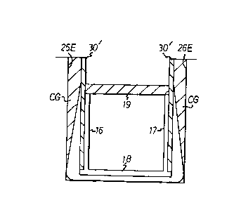
Fig. 4 is a cross-sectional view showing the side panels
in place,
Fig. 5 is a sectional view of a modification of the
invention, and
Fig. 6 is a cross-sectional view of the constructed
tunnel showing one of the frame members and the location of
rail lines, for example.
DETAILED DESCRIPTION OF THE INVENTION
The method and apparatus to be described involves
construction of underground tunnels, particularly shallow
tunnels, that is, one that is not too far below the surface or
below grade, along a given tunnel path or axis.
xl
, ,~ ,,, .. "i.a
1338281
Initially, transverse frame elements 10 (Fig. 3) are
precast above ground with keyways 11, 12, 13 and 14 in the
lateral brace columns 16, 17 which are integrally formed with
a base member 18 and, preferably, an upper transverse beam
member 19. Reinforcing steel 20 provides high tensile and
shear strength. In the case of a U-shaped frame element, the
upper cross brace member 19 may be omitted and the lower
portion of the frame will be shaped such that it is heavier at
the bottom so that the vertical legs 16 and 17 will taper from
their respective bottoms toward the top and be heavily
reinforced at the bottom because of the heavier forces or
loading at the bottom. The prefabricated and precast frames
10 have a thickness TF and are provided with lifting eyes or
hooks 20 so that they may be lowered by cable hook 2OH from a
crane into slurry filled slots 21 which are excavated
transverse to the line or axis 22 of the tunnel and have a
thickness T~ which is greater than the thickness TF Of the
frame elements 10. As shown in Fig. 2, these transverse or
cross trenches 21, 21-2, 21-3, ... 21-N are excavated by a
conventional slot excavator or clam shell element 22 while the
trenches are maintained full of an excavating slurry such as a
bentonite mud or clay 23. Typical slurry trench techniques are
disclosed in the above referenced Brunner, Miotti and Veder
patents. Insertion of precast steel reinforced flat panel
elements such as wall panels to form underground wall
structures is well known and hence need not be described in
greater detail.
~ ~ . . ~ . .
1338281
After the first pair of frame members 10 have been
inserted in the slurry filled excavation slots 21-l,
21-2...21-N, spaced pairs of cross-slots 25, 26 are excavated,
again under the presence of an excavation slurry 27, 28,
between the facing lateral edges of the steel reinforced
vertical column portions 16 and 17, frame elements 10-1, 10-2,
10-3, 10-4...10-N and a precast sidewall panel 30 is lowered
into position with its keyway or tongue and groove coupling
ends 35, 36 in interengagement with the groove or slot 11 in
one frame element and the opposite end in interengagement with
the groove or slot 14 in the next adjacent frame element 10.
The wall panels 30 have lifting means such as a lifting eye or
hook 31 received by crane hook 20H. Since the slurry filled
slots 21-1, 21-2, 21-3, 21-4...21-N are slightly larger (TE-
TF) than the frame elements 10, the frame elements can be
adjusted slightly in position and orientation so as to be
precisely positioned and accommodate and receive the
individual panel elements. Likewise, the width dimensions of
the slurry-filled slots 25-1, 26-1...25-N, 26-N, is greater
than the thickness of side panels or planks 30, the space
between the outer surfaces of panels 30 and the earthen walls
25E and 26E is filled with a cementitious grout CG.
The lateral ends of each of the wall panels are keyed
into the slots or grooves 11-12; 13-14 formed in the
respective steel reinforced vertical columns 16 and 17 of the
frame members 10. As shown in Fig. lc-e-a, the ends of the
~ . , .~ ....
1338~81
panel 30 may have a slight flare 35, 36 or enlargement to
interengage with complementary shaped slots 11 and 12,
respectively. In this case, the slots 11 and 12 are large
enough relative to the enlarged panel ends 35 and 36 to allow
adjustment of their positions. Any space is filled with a
cement grout CG. In Fig. lc-e-b, the V-shaped slots 11', 12'
respectively, with a complimentarily shaped end rib 35' and
36', respectively. In Fig. lc-e-c, the slots 11' and 12" are
rectangularly shaped. Slot 11" may be at a slight angle so as
to accommodate curves on the like portions of the tunnel. In
the cases of curves and the like, the opposing sidewall panels
30 would not be of the same length, as shown in Fig. lc for
panels 30-L and 30-R.
As shown in Fig. 5, the panels or planking 30' may extend
above the roof of the tunnel to act as retaining walls for the
shallow excavation needed to pour the roof of the tunnel. In
some cases this may be 8 to 10 feet.
Fig. 6 illustrates a partial sectional view of a rail
tunnel incorporating the invention. In this case the tunnel
is located under the median of a highway. A steel roof
support form 50 carries the conventional concrete roof 41. A
conventional invert or concrete floor structure 42 and rail
line and bed 43 are installed as illustrated. The floor or
invert 42 and the roof 50 may be poured after the walls 30
have been installed. If it is desired to reconstitute the
surface quickly, the procedure is to excavate just to the
bottom of the roof, pour the roof 41, backfill (the earth 45)
1~8281
and then go under and excavate the contained earth and just
pour the invert or floor 43 as the internal excavation of
confined soil proceeds.
While steel reinforced precast concrete frames 10 are
preferred in a broader sense, the invention can be carried out
wherein the support frames 10 are all steel beams and
channels.
By installing the tunnel precast support frames 10 first,
all cross-locked bracing that is normally done as the
excavation proceeds is dispensed with. Once these have been
placed and the precast wall panels positioned in place, the
structure is stable and the earth walls already supported.
Moreover, the bentonite slurry has penetrated the earthen
walls and stabilized same as is now well known in the art.
Thus, in essence at this point, there is no concern with
bracing as the excavation proceeds because the tunnel
excavation proceeds within stabilized form e.g. the support
frames 10 and keyed-in wall panels 30, and the only thing to
remove is the dirt, whichever way of dirt removal as is most
convenient. Thus, tunnel construction using the present
invention is faster and more economical. Since the support
frames and wall panels are precast, they have greater
uniformity and their quality can be very closely controlled.
The tunnel surfaces are better formed (smoother) and require
less finishing. Also, the cross-sections, and hence materials
used, are reduced. In slurry wall excavations, most
excavating rigs are, practically speaking, not less than about
S
~ ~.
1338281
2 feet. Sometimes they are designed to be less, but as a
practical matter clam shells, kelly rigs, etc. for this type
excavation have the 2 foot limitation. However, the tunnel
walls do not need to be that thick, the oversize of the slot
excavation is advantageous in that it allows some play so they
may be aligned perfectly. The grouting e.g. between the outer
panel surfaces and earth walls firms the panels in place and
results in an architecturally better job.
While the preferred embodiments of the invention have
been described, it is to be understood that the disclosure is
for the purpose of illustration and to enable those skilled in
the art to practice the invention, and it is intended that
other embodiments and modifications of the invention can be
made without departing from the spirit and scope of the
invention as set forth in the appended claims.
., ,~
.. .._..