Sélection de la langue

Search

Sommaire du brevet 2000064 

Énoncé de désistement de responsabilité concernant l'information provenant de tiers

Une partie des informations de ce site Web a été fournie par des sources externes. Le gouvernement du Canada n'assume aucune responsabilité concernant la précision, l'actualité ou la fiabilité des informations fournies par les sources externes. Les utilisateurs qui désirent employer cette information devraient consulter directement la source des informations. Le contenu fourni par les sources externes n'est pas assujetti aux exigences sur les langues officielles, la protection des renseignements personnels et l'accessibilité.

Disponibilité de l'Abrégé et des Revendications

L'apparition de différences dans le texte et l'image des Revendications et de l'Abrégé dépend du moment auquel le document est publié. Les textes des Revendications et de l'Abrégé sont affichés :

  • lorsque la demande peut être examinée par le public;
  • lorsque le brevet est émis (délivrance).
(12) Brevet: (11) CA 2000064
(54) Titre français: OBTURATEUR POUR TIGE DE FORAGE
(54) Titre anglais: DRILL ROD SEAL
Statut: Périmé et au-delà du délai pour l’annulation
Données bibliographiques
(51) Classification internationale des brevets (CIB):
  • F16J 15/46 (2006.01)
  • E21B 33/08 (2006.01)
(72) Inventeurs :
  • HUMMEL, KEVIN J. (Canada)
  • KELLY, MICHAEL J. (Canada)
(73) Titulaires :
  • REDPATH RAISEBORING LIMITED
(71) Demandeurs :
(74) Agent: MCCARTHY TETRAULT LLP
(74) Co-agent:
(45) Délivré: 1993-12-07
(22) Date de dépôt: 1989-10-02
(41) Mise à la disponibilité du public: 1990-12-16
Requête d'examen: 1992-09-30
Licence disponible: S.O.
Cédé au domaine public: S.O.
(25) Langue des documents déposés: Anglais

Traité de coopération en matière de brevets (PCT): Non

(30) Données de priorité de la demande:
Numéro de la demande Pays / territoire Date
07/367,056 (Etats-Unis d'Amérique) 1989-06-16

Abrégés

Abrégé anglais


ABSTRACT
For use with a raise drill or other earth or
rock drills, a seal assembly comprises a housing for the
sealing engagement with the walls at the top of the
shaft, a flexible, generally cylindrical seal for
engagement with a drill rod and an inflatable bladder
disposed between the housing and the seal and serving to
press the seal into sealing engagement with the drill
rod.

Revendications

Note : Les revendications sont présentées dans la langue officielle dans laquelle elles ont été soumises.


We Claim:
1. A fixed seal for cooperation with a drill rod of a rotary earth or rock drill,
said seal comprising:
a housing having an inner generally cylindrical surface;
means for fixing said housing at a proximal end of a shaft;
a flexible generally cylindrical seal having an outer cylindrical surface and
an inner face sealingly engageable with a drill rod, said inner cylindrical surface of said
housing and said outer cylindrical surface of said seal defining a toroidal space;
an inflatable bladder disposed in said toroidal space, said bladder by
reaction with said cylindrical surface of said housing pressing said seal into sealing
engagement with a drill rod;
an outlet in said housing communicating with a space beyond the distal end
of said seal and in close proximity with said seal;
means for connecting said outlet to an outlet conduit; and
means for fixing said seal and said housing to prevent rotation of said seal
as the drill rod rotates.
2. A seal as claimed in claim 1, wherein said housing comprises a pair ofseparable semi-cylindrical sections.
3. A seal as claimed in claim 2, wherein said housing comprises a pair ofsemi-circular flanges separably secured to said semi-cylindrical sections and extending
towards said drill rod.

Description

Note : Les descriptions sont présentées dans la langue officielle dans laquelle elles ont été soumises.

2~0006~
Thls invention relate~ to a ralse drlll or
other earth or rock drllls, and parttcularly to a seal
arrangement for such a drlll. Hereinafter, the
in~entlon will be descrlbed wlth referenc~ to its
appllcatlon to ralsQ drlll~ although lt wlll b~ apparent
that it is a~so appllcablQ to other earth and rock
drills.
In mlnlng and ln other proce~ses lnvolv~ng
rock drllling, it i~ conventlonal to drtll a pilot shaft
from one level ( whlch may be the surfacQ) to another
uslng a ralse drlll and alr and water or other
coolant/cl~aner 19 dellvered at hlgh preRQurQ to the
drill blt through a hollow drlll rod. That alr and
water mlxes wlth drlll blt f~nes to form a slurrv whlch
18 forced up the outslde of the drlll ro~ to the surface
or othQr level from whlch drlllln~ 1~ besun.
~he present lnventlon ~eek~ to provldQ a sRal
for dlsposltlon about the upper end of the drlll rod to
prevent the uncontrolled egress of the ~lurry.
Accordlng to thl~ lnventlon, ther~ 1~ provlded
a fked seal for cooperation with a drill rod of a ro~uy earth or rock drill, said seal
comprising:
a housing having an inner gene~ally cylindrical surface;
means for fixing said housing at a proximal end of a shaft;
a fle~ible generally cylindrical seal having an outer cylindrical surface and
an inner face sealingly engageable with a drill rod, said inner cylindrical surface of said
housing and said outer cylindrical surface of said seal defining a toroidal space;
an in~atable bladder disposed in said toroidal space, said bladder by
reaction with said cylindrical surface of said housing pressing said seal into sealing
engagement with a drill rod;
an outlet in said housing communicating with a space beyond the distal end
of said seal and in close proxi nity with said seal;
means for connecting said outlet to an outlet conduit; and
means for fi~ing said seal and said housing to prevent rotation of said seal
o "~ asthedrillrodrot~tes.
~ . . . - . . :.
..
: ,
- - . ~. .
- ~ - : . , -

~oo~
A preferred embodiment of the invention ls
illustrated in the accompanying drawings in which:
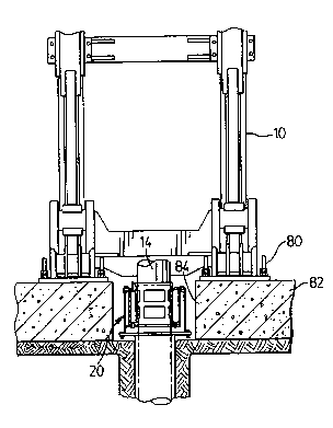
Figure 1 i a front elevatlonal vlew of a
rais~ drlll and seal assembly with slgnlficant parts
omlt~ed ln the intarest of clarlty;
Flyure 2 is a slde vlew of the assembly of
Flgure l;
Flgure 3 is a cross ~ectlon taken on tha line
3-3 of Figure 4 of tha seal assembly according to the
present inventlon:
Figure 4 ls a plan v~ew of the seal assembly
of Figure 3;
Flgure 5 iQ an exploded vlQw showing the
assembly of Figures 3 and 4; and
Flgure 6 is a perspe~tlve view of the bladder
of the se~l assembly according to this lnventlon.
lS T~o ral~e drlll assembly lllustrated
schem~tically and pastially ln Figure 1 18 of entlrely
conventlonal form and ln p~rtlcular 18 of the kind known
by the trade mark REDBOR8 40 manufactured by Redpath
Manufacturlng ~td. It comprlses a maln body assembly 10
whlch is turnabl~ about pivots 12 to permlt shafts to be
drllled at dlf ferent angles. In th~ interests of
clarlty, the drlve assembly, thrust assembly and plpe
loader assembly are omitted.
A drlll rod sectlon is shown at 14 and the
seal assembly for co-operatlon wlth the drill rod i8
llluqtrated at 20. That seal is more fully lllus~rated
ln F~gures 3, 4 and 5 and lts component p~rts are more
clearly shown ln Figur~ 5. ~h~y comprlRa a lower hou~lng
lndlcated gen~rally at 22 and comprl~ing an open ended
cyllndr~cal body 24 wlth an annular, radlallydisposed
~lange 26 at it~ upper end. An upper hou-Qlng 30
comprlseq a palr of seml-cylindrlcal -qhell~ 32, each of
whlch has an outer Qllndrlcal wall 34 and a spa ed,
inner cyllndr~cal wall 36. The outsr waLls have ~emi -
annular flanges 38 at thelr lower edges and tha ~lange8
38 and fl~nge 26 o the lower housing are pre-dr~lled so
2 -
. . - .
:. . . ~ .
,

- 20V0064
. . .
that they may be bolted together. A gasket 40 is
provided to seal the interface between the flange~.
The inner wall 36 terminates short o the
lower edge of the outer wall 34 and an annular 1ange
brldges the space between the two walls and proJects
radlally inwardly of the inner wall a~ at 42.
The gap between the lnner and outer walls at
the top of the shQlls is closed by Qemi circular plates
44 which are pre drllled to receive cover plate sections
46 which proJect inwardly of the inner wall 36 ln the
same manner as doe~ plate 42.
The oppo3ed edge~ of the ~hells have
longltudlnally extending and radlally dlspo~ed flanges
48 whlch are Jolned together by bolting wlth sealing
gaskets 50 ~tween their opposed face~.
A seal 60 haQ a generally cylindrical body 62
wlth an upper flared lead in surface 64 and an annular
radial flange 66. The flange 66 i~ pre-drllled to match
the holes ln plate 42 and 1~ secured to that plate by
nuts, bolts and washers.
Thus, the outer ~urface of the cylindrlcal
part of the body 62 and the lnner surface of the inner
wall of the upper hou~lng form an annular space. A
bladder 72 havlng an inflation valve 74 is disposed in
thl~ space.
The seal is of resilient rubber material and
it w111 be apparent from a consiaeratlon of Figure 3
that the inflatlon of the bladder wlll cause the seal to
be pressed flrmly against the outer surface of the drill
rod.
Secured to one half shell of the upper housing
is an ou'clet or reducer 76 which communicates wlth the
space between the outer wall of the hou~ing and the
drill rod and lead3 to a conduit so that slurry reaching
the seal will be dlverted to a condult for controlled
dlsposalO
-- 3 --
, ~
. , .
,
:: :
,

2000~
Figure 6 illustrate~ thQ particular bladder
utilized and lt wlll be seen that it comprises simply a
~ closed ended tube whlch iq turned about the inner
qurface of the inner wall of the shells to form a
torlodal shape.
Reference i3 now made to Flgure~ 1 and 2. In
installing the drill and ~eal, the maln body 1~ first
secured in place by conventional rock bolt3 indlcated at
80. Most usually, this 1~ done on a concretQ pad as at
82 and a well i3 l~ft below tho feet of the drlll as at
84.
Firstly, a hole i~ drilled in the rock to a
depth equal, approximately, to the length of ths lower
housing and of a diameter into which that hou~in~ may
lS f~t. The lower housinq 1~ then ln~talled and sealed
against the wall-q of the shaft elther w~th burlap or
wlth ~routlng.
The rubber seal i~ then applied to the dril1
rod and the dri~l bit in~e~tsd into the drlll hole. The
two shell~ forming the upper housin~ are then bolted
about the drill rod and sacured to the upper flange of
the lower housing. T~e rubber bladder i~ then inserted
into thq ~pace between the 3eal and the lnnsr ~urface of
the inner wall of tha upper houQlng and thQ cover plate,
mads up of plates 44, bolted ln placa at the top of the
upper hou~ing. ThereaftQr, the bladder i~ inflated to
pre-~s the seal into tight contact wlth the drill rod.
Of course, the outlet i~ s2cused to the condult for the
Qlusr~r-
ThQ preqent invent~on provlde~ ~ simple and
convenlent solutlon to a pro~lem whlch has e~ted for
many years t n the mlnlng and othes art lnvolvlng rock
drllling whlch 1Q effective and which accommodate~ wear
$n the se~l ~y expanqlon of the bladder or, lf need be,
3s re-inflatlon of the bladder.
r.; ~ 4
`~
. ~ .
'' ' .

Dessin représentatif
Une figure unique qui représente un dessin illustrant l'invention.
États administratifs

2024-08-01 : Dans le cadre de la transition vers les Brevets de nouvelle génération (BNG), la base de données sur les brevets canadiens (BDBC) contient désormais un Historique d'événement plus détaillé, qui reproduit le Journal des événements de notre nouvelle solution interne.

Veuillez noter que les événements débutant par « Inactive : » se réfèrent à des événements qui ne sont plus utilisés dans notre nouvelle solution interne.

Pour une meilleure compréhension de l'état de la demande ou brevet qui figure sur cette page, la rubrique Mise en garde , et les descriptions de Brevet , Historique d'événement , Taxes périodiques et Historique des paiements devraient être consultées.

Historique d'événement

Description Date
Inactive : CIB de MCD 2006-03-11
Inactive : Demande ad hoc documentée 1996-10-02
Le délai pour l'annulation est expiré 1996-04-02
Lettre envoyée 1995-10-02
Accordé par délivrance 1993-12-07
Exigences pour une requête d'examen - jugée conforme 1992-09-30
Toutes les exigences pour l'examen - jugée conforme 1992-09-30
Demande publiée (accessible au public) 1990-12-16

Historique d'abandonnement

Il n'y a pas d'historique d'abandonnement

Taxes périodiques

Le dernier paiement a été reçu le 

Avis : Si le paiement en totalité n'a pas été reçu au plus tard à la date indiquée, une taxe supplémentaire peut être imposée, soit une des taxes suivantes :

  • taxe de rétablissement ;
  • taxe pour paiement en souffrance ; ou
  • taxe additionnelle pour le renversement d'une péremption réputée.

Veuillez vous référer à la page web des taxes sur les brevets de l'OPIC pour voir tous les montants actuels des taxes.

Historique des taxes

Type de taxes Anniversaire Échéance Date payée
TM (demande, 2e anniv.) - générale 02 1991-10-02
Titulaires au dossier

Les titulaires actuels et antérieures au dossier sont affichés en ordre alphabétique.

Titulaires actuels au dossier
REDPATH RAISEBORING LIMITED
Titulaires antérieures au dossier
KEVIN J. HUMMEL
MICHAEL J. KELLY
Les propriétaires antérieurs qui ne figurent pas dans la liste des « Propriétaires au dossier » apparaîtront dans d'autres documents au dossier.
Documents

Pour visionner les fichiers sélectionnés, entrer le code reCAPTCHA :


Pour visualiser une image, cliquer sur un lien dans la colonne description du document. Pour télécharger l'image (les images), cliquer l'une ou plusieurs cases à cocher dans la première colonne et ensuite cliquer sur le bouton "Télécharger sélection en format PDF (archive Zip)" ou le bouton "Télécharger sélection (en un fichier PDF fusionné)".

Liste des documents de brevet publiés et non publiés sur la BDBC .

Si vous avez des difficultés à accéder au contenu, veuillez communiquer avec le Centre de services à la clientèle au 1-866-997-1936, ou envoyer un courriel au Centre de service à la clientèle de l'OPIC.


Description du
Document 
Date
(aaaa-mm-jj) 
Nombre de pages   Taille de l'image (Ko) 
Dessins 1996-06-18 4 106
Page couverture 1996-06-18 1 18
Revendications 1996-06-18 1 30
Abrégé 1996-06-18 1 11
Dessins représentatifs 2000-02-24 1 15
Description 1996-06-18 4 167
Taxes 1991-09-11 1 32
Correspondance 1992-02-03 1 34
Taxes 1992-10-01 1 40
Taxes 1993-09-27 1 37
Taxes 1994-09-30 1 46
Correspondance reliée au PCT 1989-10-02 3 91
Correspondance reliée au PCT 1990-03-05 2 28
Courtoisie - Lettre du bureau 1990-01-18 1 130
Courtoisie - Lettre du bureau 1992-11-17 1 39
Correspondance reliée au PCT 1993-09-16 1 23
Correspondance de la poursuite 1992-09-30 1 30
Correspondance de la poursuite 1992-12-02 1 27
Correspondance de la poursuite 1992-09-30 2 55