Note : Les descriptions sont présentées dans la langue officielle dans laquelle elles ont été soumises.
~q~ 5~`,5
AORTICALLY LOCATED BLOOD PUMPING
C~THETER AND METHOD OF USE
Fleld of the Invention
Thls invention relates genera:Lly to medical
instruments and more particularly to catheter based instruments
for effecting the pumping o~ blood through the vascular system
of a being and methods of using the same.
Background Ar-t
Medical apparatus have been disclosed and are in
use today to take over and/or to supplement the action of the
heart to effect the pumping of blood into the vascular system.
One particularly well known type of apparatus is the so-called
"heart-lung" machine. Such prior art apparatus for effecting
heart pumping action are necessarily complex and expensive.
Most significantly such prior art devices are not suitable for
general or widespread usage. In this connection, such prior
art devices invariably require the services of skilled medical
personnel, e.g., surgeons, under stringent surgical conditions
for effecting the placement, connection and operation of the
devices. Accordingly, various prior art blood pumpiny
apparatus have not been deemed suitable for general or
emergency usage to supplement or replace the pumping action of
a person's heart.
In United States Patent 4,625,712 (Wampler)
there is disclosed a cardiac assist de~ice in the Eorm of a
catheter having a small fixed size bladed pump at its distal
end which is arranged to be passed by retrograde insertion
through the aortic valve. The pump must necessarily be of a
small size to enable the ready insertion of the catheter
through the aortic valve. Thus, the device of the Wampler
patent appears to be of limited blood pumping capacity.
In the United States Patent ~,753,221, entitled
~lood Pumping Catheter and Method of Use, of which I am a
coinventor, and which is assi~ned to the same assignee as this
invention, and whose disclosure is incorporated by reference
herein, there :is disclosecl and claimed an instrument and a
method of use which overcomes the disadvantages o~ the prior
art, such as the Wampler patent.
~ ;5;~t~
To that end the instrument disclosed ln my
aforenoted patent is in the form of an elongated catheter
having a distal end portion which is of sufficiently small
diameter and sufficient flexibi]ity to enable it to be passed
through a portion o~ the being's vascular system so that the
distal end portion of the catheter is located within or closely
adjacent the being 15 heart. The catheter includes an
expandable pump located at the distal end portion and drive
means for effecting the operation of the pump. The distal end
portion of the catheter includes an inlet for blood to flow
therein and an outlet for blood to flow thereout. The
instrument can be used for either left side heart applications
or right side heart application. When used for left side heart
applications, the catheter is constructed so that the inlet is
in fluid communication with the left ventricle while the outlet
is in fluid communication with the aorta. When used for right
side heart applications, the catheter is constructed so that
the inlet is in fluid communication with the right ventricle
while the outlet is in fluid communication with the pulmonary
artery. In one embodiment of that patent, the distal end
portion of the instrument extended through -the aortic valve.
In another embodiment of that patent, the distal end portion is
located over the aortic valve and includes a cover for that
valve while enabling blood to flow therethrough. In all cases
the blood can be pumped through the heart and into the vascular
system without reguiring any pumping action of the heart
itself.
While the instrument and method of use disclosed
in my foregoing patent is suitable for its intended use, the
location O e its distal end portion either through or over
(i.e., immediately adjacent) the aortic valve limits the use of
the device somewhat.
~i,ects f the I vention
Accordingly, it is the general object of this
invention to provide medical apparat~ls which overcomes the
disadvantages of the prior art.
It is a further object of the instant invention
to provide minimally invasive medical apparatus for taking over
or supplementing the pumping act~on of the heart and which need
not be located through or immediately adjacent the aortic
valve.
It is a further object o e this invention to
provide minimally invasive catheter/pump apparatus which is
simple in construction.
It is still a further object of this invention
to provide a minimally invasive catheter/pump apparatus which
readily loca-table within the aorta at a location remote from
the aortic valve and which is easy and safe to use.
Summary of the Invention
These and other objects of the instant invention
are achieved by providing a method and apparatus for pumping of
blood through at least a portion of a living being's vascular
system. The apparatus, in the form of an elongated catheter
having a distal end portion, is introduced into the aorta so
that the distal end portion is at a predetermined position in
the aorta spaced away from the aortic valve. The catheter
comprises pump means located at the distal end portion, barrier
means located at the distal end portion, and drive means
coupled to the pump means. The distal end portion of the
apparatus comprises an inlet and an outlet. The apparatus is
positioned so that the distal end portion is at the
predetermined position with the inlet in fluid communication
with the aorta distally of the pump means, the outlet in fluid
communication with the aorta proximally of the pump means, and
with the barrier means in engagement with the inner periphery
of the aorta at the predetermined position. The pump means is
operated by the drive means to pump the blood through the
aorta. The barrier means ensures that substantially all of the
blood flowing through the aorta flows into the inlet -to the
pump ~eans and out the outlet from the pump means and not
around the exterior of the distal end portion of the apparatus
a.s the pump means is operated.
Briee Descrl~tion of the Drawinqs
Other obj ects and many of the attendant
advantages of this invention will be readily appreciat.ed as the
same becomes better understood by reference to the following
detailed description when considered in connectlon with the
accompanying drawings wherein:
Fig. 1 is a perspective view of the distal end
of the apparatus constructed in accordance with the subject
invention;
Fig. 2 is an enlarged sectional view taken
along line 2-2 of Fig. l and showing the device of Fig. l in
its operative state to pump blood to the being's vascular
system; and
Fig. 3 is an enlarged sectional view taken along
line 3-3 of Fig. 2.
Detailed Description of the Preferred Embodiment
Referring now in detail to the various figures
of the drawing wherein like reference characters refer to like
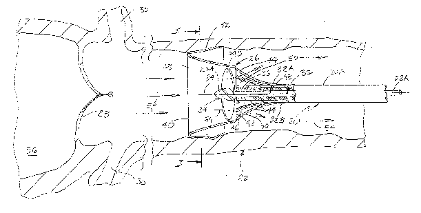
parts, there is shown at 20 in Fig. 1 apparatus constructed in
accordance with the subject invention. That apparatus is
arranged to be disposed within the vascular system, and in
particular, the aorta 22 (Fig. 2) to effect the pumping of
blood through the vascular system. Thus, the apparatus
basically comprises a catheter having pumping means 24 located
at its distal end portion 26. The details of the apparatus 20
will be described in detail later. Suffice it for now to state
that catheter comprises an elonga-ted outer tube or jacket 20A
of small diameter, e.g., 5 to 10 French (1.7-3.3 mm), with
various components located therein and with the pumping means
24 and barrier means, to be described later at its distal end
portion 26. The catheter is sufficiently flexible to enable it
to be passed through the vascular system to its desired
position within the aorta remote (i.e., downstream) from the
aortic valve 28 (Fig. 2). The positioning of the catheter 20
is carried out through the use of a conventional tubular guide
catheter (not shown), which is first introduced and threaded
through the vascular system in a convention manner.
For example, the catheter 20 is inserted
percutaneously into the femoral artery (not shown), up through
the descending aorta (not shown) until it5 distal end portion
26 is located at a desired position within the aorta 22
downstream of the aortic valve 28 and downstream of the
2~ r~?s~
junction of the coronary arteries 30 to the aorta. Thus, the
distal end portion 26 may be located within the ascending
aorta, the aortic arch or the descending aorta, as desired.
As can be seen clearly in Fig. 2 the distal end
portion 26 of the catheter 20 includes the heretofore
identified pu~lp means 24. That means can take various forms
such as those disclosed in my aforenoted U.S. Patent No.
4,753,221. Thus, the pump means 24 is preferably a centrifugal
pump which is arranged to be operated, e.g., rotated, by drive
means 32 shown. The drive means 32 can take various forms, but
preferably comprises the high speed rotary drive system
described and claimed in my United States Patent 4,606l902
entitled Spiral Wire Bearing for Rotating Wire Drive Catheter,
and in my copending United States Patent Application Serial No.
938,698 filed on December 5, 1986, entitled Catheter with Means
to Prevent Wear Debris From Exiting, said patent and said
application are both assigned to the same assignee as this
invention, and the disclosures of both are incorporated by
reference herein.
Basically that drive system comprises an
elongated drive wire or cable 32A supported in the center of
the catheter tube 20A, that is, along its central lonyitudlnal
axis 34, by means of a spiral bearing 32B. That bearing
comprises a he]ical or spiral coil of wire extending
substantially the entire length of the catheter tube from a
proximately located point outside the body to the distal end
portion of the catheter. The outer diameter of helical bearin~
is sufficiently great so that its loops just clear the interior
surface of the catheter tube 20A to hold the bearing securely
in place therein. The inside diameter of the central passage
extending down the length of the helical bearing i.s just
slightly greater than the outside diameter of the dri.ve cable
so the drive cable can rotate freely thereirl.
In the interests of reducing the size of any
wear debris created by the rotation of the drive cable within
the spiral bearing, the drive cable may be swaged or drawn to
increase the engaginc~ surface area thereof, while the cross-
sectional shape of the spiral bearing can be rectangular to
5~
also increase the engaging surface area, as disclosed in my
aforenoted copending application.
The drive cable is arranged to be connected at
the proximal end thereof to an electric motor (not shown) or
some other drive means for rotating the cable at a high rate of
speed, e.g., from 10,000 to 200,000 rpm, to effect the
operation of the pump 2~.
The distal end portion of the catheter is of a
generally tubular construction which is arranged to be expanded
from a compacted orientation (not shown) to an expanded
orientation (like that shown in Figs. 1-3), and vice versa.
When the distal end portion is in the compact orientation its
outside diameter is sufficiently small to enable the catheter
to be readily inserted longitudinally into the aorta, via a
percutaneous insertion at a desired location, e.g., into the
femoral artery. Once the catheter is within -the aorta, and in
particular at the desired position at which it is to be
operated, the distal end portion is expanded to the expanded
orientation shown in the drawing.
The pump 24 is an expandable/contractible member
so that when the distal end portion of the catheter is
expanded, automatically expands from a closed or compact
position to the open, operative position.
In the embodiment shown herein, the pump 2~s is
an axial type pump basically comprising a central hub 2~A from
which four blades or impellers 24B extend. The blades are
biased to naturally project outward radially. However, the
blades are formed of flexible material so that when the distal
end portion of the catheter 20 is compacted (unexpanded) the
blades are flexed into t~le closed or compressed position
extending beside one another. When released or freed they
extend radially outward from the hub 2~A. Moreover each of the
blades 2~B i.s angled so that when the pump is rotated about the
central axis 3~ oE the catheter the blades 2~ draw blood from
the heart inko an inlet (to be described later) in the distal
end portion of the catheter to the blades and from there the
blades force the blood out o~ an outlet in the direction of
arrows (to be described later) into the aorta 22.
~ he proximal end of the hub 24A is connected to
the distal end of the drive cable 32A so that the rotation of
cable causes the concomitant rotation of pump's blades 2~s.
The edges of each of the blades 24B are
preferably rounded so as not to present any sharp edges which
could adversely affect the blood cells pumped thereby.
The pump 24 is held in position centered within
the device's distal end portion by a bearing support 36.
As can be seen the distal end portion of the
catheter 20 is in the form of a cup-shaped member 38. The
member 38 is formed of some other flexible and/or resilient
material, e.g., an elastomeric material. The member 38 is
tubular in shape, e.g., it constitutes a truncated cone,
including an enlarged diameter open free end 40 located at the
distal end thereof and a smaller diameter open end 42 located
at the proximal end thereof. The cup-shaped member 38 is
mounted on the sleeve 20A forming the outer wall of the
catheter at the distal end thereof via a plurality of resilient
fingers 44. The fingers extend at equally spaced locations
about the periphery of the catheter's sleeve 2OA. Each finger
44 is formed of a resilient material and is slightly arcuate in
shape. The distal end 46A of each of the fingers 4A is fixedly
secured to the outer periphery of the cup-shaped member
immediately adjacent the opening 42 while the proximal end
portion 48B of each of the fingers 44 is fixedly mounted to the
catheter sleeve or tube 20A. Each of the fingers 44 is biased
radially outward so that when unconstrained, they more to the
expended position shown in the drawings, thereby expanding the
cup-shaped member 38 from a compacted orientation (not shown),
in which it is somewhat like a folded umbrella, to the expanded
orientation shown. The fingers 44 and the cup-shaped member 38
are arranged to be compressed or contracted radially inward by
being disposed within the tubular guide andjor introducing
catheter (not shown) during placement of the device 20 in the
patient. In particular, the de~ice is arranged to be inserted
through a conventional tubular yuide/introducing catheter into
the body to the desired position within the aorta and the
guide/introducing catheter is then retracted to expose the
5'l:~5
distal end portion of device 20. This action enables the
resilient fingers 44 to move radially outward to the position
shown, thereby causing the cup-shaped member 38 to also assume
the expanded orientation shown.
In normal operation the flared open end 40 of
the cup-shaped member 38 serves as the inlet to the pump 24,
while the smaller diameter opening 42 and the open spaces 50
between the fingers 44 contiguous with the opening 42 serves as
the outlet from the pump. Thus the pump is located so that its
blades are disposed within the cup shaped member 38 between the
inlet and the outlet.
In order to ensure that substantial all, if not
all, of the blood which will flow through the aorta flows into
the pump's inlet (and not around the outside of the catheter),
the distal end portion of the catheter includes the heretofore
mentioned barrier means. That means is in the form of a
barrier wall or a flexible skirt 62 which extends about the
periphery of cup-shaped member 38 contiguous with the opening
(inlet) 40. The skirt is very flexible so that it engages and
conforms to the periphery of the inner surface of the aorta as
shown clearly in Figs. 2 and 3. This action has the effect of
isolating the portion of the aorta 22 upstream (distally) of
the pump from the portion of the aorta downstream (proximally)
of the pump, except for the passagewa~ through the pump itself,
i.e., through the cup-shaped member 38 from the inlet to the
outlet. Accordingly, when the pump is operated at a relatively
high speed, e.g., 10,000-100,000 RP~, higher pressure is
produced in the aorta downstream of the barrier wall than
upstream. This action causes blood to be drawn in the
direction of arrows 54 from the heart 56 through the aortic
valve 28 into the pump's inlet 40, from whence it flows to the
pump's outlet fi2, 50 and from there into the aorta 22 for
passage to the remainder of the person's vascular system.
In some application, e.g., to ensure that
sufficient b].ood flows into the coronary arteries 30, the
operation of the catheter's pu~p will be coordinated with the
pump.ing action of the heart. q'hus, for such applications the
speed of the pump is cycled, i.e., slowed down or stopped, in
~ D
synchronism with the pumping action of the heart 50 that there
will be repetitive periods when the higher pressure downstream
of the pump pushes the blood upstream of the pump into the
coronary arteries. The pump speed/time cycle can be
established and/or adjusted to anything desired.
Not only does the barrier wall 52 provide the
isolation function described above, it also serves to hold the
distal end of the catheter at the desired operative position
within the aorta.
As will be appreciated from the foregoing since
the catheter is arranged to be located at a position remote
from the heart and the aortic valve, it can be used by less
skilled personnel than would otherwise be re~uired if the
catheter had to be located into the heart through the aortic
valve or immediately over the aortic valve. Moreover, some
medical situations, e.g., a patient having a calcified aortic
valve or whose heart has stopped beating, may not be conducive
to the disposition of a catheter through or immediately over
the aortic valve. It is for such applications that the subject
catheter is particularly suited. Furthermore, the location of
the distal end of the catheter remote from the aortic valve
ensures that the entrance to the coronary arteries is not
blocked by any portion of the catheter.
Without further elaboration, the forgoing wlll
so fully illustrate my invention that others may, by applying
current or future knowledge, readily adopt the same for use
under various conditions of service.