Sélection de la langue

Search

Sommaire du brevet 2001073 

Énoncé de désistement de responsabilité concernant l'information provenant de tiers

Une partie des informations de ce site Web a été fournie par des sources externes. Le gouvernement du Canada n'assume aucune responsabilité concernant la précision, l'actualité ou la fiabilité des informations fournies par les sources externes. Les utilisateurs qui désirent employer cette information devraient consulter directement la source des informations. Le contenu fourni par les sources externes n'est pas assujetti aux exigences sur les langues officielles, la protection des renseignements personnels et l'accessibilité.

Disponibilité de l'Abrégé et des Revendications

L'apparition de différences dans le texte et l'image des Revendications et de l'Abrégé dépend du moment auquel le document est publié. Les textes des Revendications et de l'Abrégé sont affichés :

  • lorsque la demande peut être examinée par le public;
  • lorsque le brevet est émis (délivrance).
(12) Brevet: (11) CA 2001073
(54) Titre français: CHAISE DE PALIER INTERMEDIAIRE POUR ARBRE D'ENTRAINEMENT
(54) Titre anglais: INTERMEDIATE BEARING SUPPORT FOR A DRIVE SHAFT
Statut: Périmé et au-delà du délai pour l’annulation
Données bibliographiques
(51) Classification internationale des brevets (CIB):
  • B60K 17/00 (2006.01)
  • B60K 17/24 (2006.01)
  • F16C 27/06 (2006.01)
  • F16C 33/72 (2006.01)
  • F16C 33/76 (2006.01)
  • F16F 01/377 (2006.01)
(72) Inventeurs :
  • MAZZIOTTI, PHILIP J. (Etats-Unis d'Amérique)
(73) Titulaires :
  • ZELLER CORPORATION (THE)
(71) Demandeurs :
  • ZELLER CORPORATION (THE) (Etats-Unis d'Amérique)
(74) Agent: MACRAE & CO.
(74) Co-agent:
(45) Délivré: 1999-12-21
(22) Date de dépôt: 1989-10-19
(41) Mise à la disponibilité du public: 1990-04-24
Requête d'examen: 1996-10-01
Licence disponible: S.O.
Cédé au domaine public: S.O.
(25) Langue des documents déposés: Anglais

Traité de coopération en matière de brevets (PCT): Non

(30) Données de priorité de la demande:
Numéro de la demande Pays / territoire Date
261,618 (Etats-Unis d'Amérique) 1988-10-24

Abrégés

Abrégé anglais


An intermediate bearing support for a drive shaft of a
vehicle is set forth. An intermediate drive shaft support
is required when three or more universal joints are embodied
in a drive line between a transmission and a differential.
The new drive shaft support is more compact, uses fewer parts
which is brought about in part by the use of symmetrical
designs, and is easier to assemble on a drive shaft. Bearing
shields or flingers of the support are mounted on the drive
shaft adjacent a bearing of the support so that the shields
do not have to be specially designed to fit particular drive
shafts. For replacement purposes, one replacement kit can
be used to rebuild a number of different drive shaft
bearing supports.

Revendications

Note : Les revendications sont présentées dans la langue officielle dans laquelle elles ont été soumises.


THE EMBODIMENTS OF THE INVENTION IN WHICH AN EXCLUSIVE PROPERTY
OR PRIVILEGE IS CLAIMED ARE DEFINED AS FOLLOWS:
1. A shaft support for a drive shaft of a drive line of a
vehicle, said shaft support comprising an inner race having an
inner diameter of predetermined value, an outer race, and
bearing elements therebetween, a grease retainer of generally
U-shaped transverse cross section around said outer race, a
resilient cushion member extending around said retainer, said
cushion member having annular flanges extending away from said
retainer, a supporting bracket extending around said cushion
member and having means to attach said bracket to a portion of
the vehicle, two flingers, one located on each side of said
inner race, each of said flingers having an inner mounting
flange having a circular inner edge of a diameter substantially
equal to said inner diameter of said inner race, said mounting
flange being positioned adjacent an annular edge of said inner
race, and a protective flange extending outwardly beyond said
outer race in a generally radial direction from the shaft.
2. A shaft support according to claim 1 characterized by
each of said flingers further having an annular flange extending
away from an outer extremity of said mounting flange and being
structurally integral therewith, said protective flange
extending from an extremity of said annular flange of said
flinger and being structurally integral therewith.
-9-

3. A shaft support according to claim 1 characterized by
said protective flange of each of said flingers extending
outwardly beyond the corresponding annular flange of said
cushion member and having an outer portion extending inwardly
toward said cushion member.
4. A shaft support according to claim 1 characterized by
said protective flange of each of said flingers extending
outwardly beyond said grease retainer and having an outer
portion extending inwardly toward said cushion member.
5. A shaft support according to claim 1 characterized
further by a retaining collar having an inner diameter
substantially equal to the inner diameter of said inner race and
being located adjacent an edge of said inner race with the
mounting flange of one of said flingers being positioned
therebetween.
6. A universal replacement kit to replace a number of
special kits for a shaft support for a drive shaft of a drive
line of a vehicle, said replacement kit comprising a bearing
having an inner race with an inner diameter of predetermined
value, an outer race, and bearing elements therebetween, two
grease retainer halves which, when in face-to-face relationship,
form a U-shaped cross section, a resilient cushion member having
an opening of a size and shape to encompass outer surfaces of
-10-

said grease retainer halves when in face-to-face relationship,
a support bracket of a size to extend around said cushion member
and having means to attach said bracket to a portion of the
vehicle, a pair of flingers of symmetrical shape, each having an
inner circular mounting flange having a circular inner edge of
a diameter substantially equal to said inner diameter of said
inner race, and a protective flange extending away from said
mounting flange, said protective flange having a first, inner
portion extending outwardly and away from said cushion member
when in assembled relationship therewith, and a second, outer
portion extending outwardly from an outer extremity of said
inner portion and back toward said cushion member when in
assembled relationship therewith, said inner and outer portions
extending around outer extremities of said cushion member when
said cushion member and said flanges are in assembled
relationship.
7. A replacement kit according to claim 6 characterized by
each of said flingers having an annular flange extending from an
outer extremity of said mounting flange and structurally
integral therewith, said protective flange extending outwardly
from an extremity of said annular flange of said flinger and
being structurally integral therewith.
8. A replacement kit according to claim 6 characterized
further by said kit having a retaining collar having an inner
-11-

diameter substantially equal to the inner diameter of said inner
race.
9. In combination, a shaft of a drive line of a vehicle,
said shaft having an annular, outwardly-extending shoulder, a
shaft support for said shaft, said support comprising an inner
race affixed to said shaft adjacent said shoulder, an outer
race, and bearing elements between said inner and outer races,
a grease retainer having a U-shaped transverse cross section
around said outer race, a resilient cushion member extending
around said retainer, said cushion member having annular flanges
extending outwardly beyond said retainer, a supporting bracket
extending around said cushion member and having means to attach
said bracket to a portion of the vehicle, two flingers, one
located on each side of said inner race, each of said flingers
having an inner mounting flange having a circular inner edge of
a diameter substantially equal to an inner diameter of said
inner race, and a protective flange extending outwardly beyond
said outer race, one of said mounting flanges being positioned
between an edge of said inner race and said shaft shoulder, and
means holding the mounting flange of the other flinger adjacent
the other edge of said inner race.
10. The combination according to claim 9 characterized by
said last-named means being a retaining ring mounted on said
drive shaft.
-12-

11. The combination according to claim 9 characterized by
said last-named means being another shoulder on said drive
shaft.
12. The combination according to claim 9 characterized by
outer edge portions of said protective flanges beyond said
annular flanges of said resilient cushion extending inwardly
toward said resilient cushion member.
13. The combination according to claim 12 characterized by
said outer portions of said protective flanges extending closer
to said cushion member than the extremities of said annular
flanges of said cushion member.
14. The combination according to claim 9 characterized by
each of said flingers having an annular flange extending from an
outer extremity of said mounting flange and being structurally
integral therewith, an outer extremity of said annular flange of
said flinger extending beyond a corresponding extremity of said
retainer.
-13-

Description

Note : Les descriptions sont présentées dans la langue officielle dans laquelle elles ont été soumises.

2n(l~(~'~3
This invention relates to an intermediate bearing sup-
port for a drive shaft and to a replacement kit embodying
same.
In some drive lines, three or more universal joints are
required between the transmission and the rear axle differ-
ential because a single, straight shaft cannot be used.
Also, particularly in larger vehicles, the drive or propeller
shaft may be. sufficiently long that it tends to flex or whip
to an objectionable extent. In either of these applications,
an intermediate bearing support for the drive line is employed.
An intermediate bearing support for a drive shaft commonly
includes a ball bearing with an inner race mounted on the
II shaft, a grease retainer around an outer race of the bearing,
a cushion block around the grease retainer, and a hanger lo-
cated around the cushion block and being mounted on suitable
framework of the vehicle. Beaxing shields or flingers are lo-
Gated on each side of the roller bearing. Heretofore, the bear-
ing shields have been mounted on spaced portions of the drive
shaft and must be specially. designed for each particular shaft.
The new intermediate drive shaft support has certain
components designed symmetrically for easier manufacturing and
for facilitating assembly of the support on a shaft, with'.
less chance for error. Also, with the symmetrical design
~~ -2-

i i z~(~ zc~~~
of certain components, fewer different components are re-
quired. In the new dxive shaft support, the bearing shields
or flingers are mounted on the drive shaft in contiguous re-
lationship with the inner ~ace of the~ball bearing so that
the flingers will fit any shaft that the bearing will. Con-
sequently, with the overall design, one drive shaft support
replacement kit can be used to rebuild drive shaft supports of
a number of different designs. A smaller inventory of
replacement kits is thereby achieved and there is less chance
~ of obtaining the wrong kit when rebuilding a shaft support.
It is, therefore, a principal object of the invention
to provide a drive shaft support or replacement kit which is
capable of being used to rebuild drive shaft supports of a
number of different designs. Another object of the invention
is to provide a drive shaft support using more symmetrical
components for ease in manufacture and less chance for errors
in assembly.
Still another object of the invention is to provide a
drive shaft support which is more compact and can be mounted
on drive shafts of various configurations.
Xet another object of the invention is to provide a drive
shaft support with bearing shields located on the shaft im-
mediately contiguous with a bearing of the support.
~~ -3-

2~~Ulc~ l3
Many other objects and at3vantages of the invention will
be apparent from the following detailed description of
preferred embodiments thereof, reference being made to the
accompanying drawings, in which:
S Fig, 1 is a schematic view in elevation of a drive line
of a vehicle with which the drive shaft support is used;
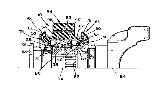
Fig. 2 is an enlarged view in transverse cross section
of one-half of the drive shaft support of Fig. 1, with a
drive shaft component shown in elevation;
I) Fig. 3 is an exploded view in perspective of the drive
shaft support of Fig. 2; and
'Fig. 4 is a view similar to Fig. 2 of a slightly modified
drive shaft support.
II Referring to Fig. 1, a drive shaft support 10 is shown
in a typical application. Here a vehicle engine 12 with a
transmission 14 is connected to a rear axle differential 16
by front and rear drive shafts 18 and 20. A front universal
joint 22 connects the shaft 18 with the transmission 14 and a
~~ rear universal joint 24 connects the rear drive shaft 20 with
the differential 16. The shafts 18 and 20 are connected by an
intermediate universal joint 26. The drive shaft support 10
is required to provide an intermediate support for the drive
shafts and specifically supports the rear portion of the front
II drive shaft 18 near the intermediate universal joint 26. The
drive shaft supports 10 are also used on single, straight
drive shafts when of substantial length, to prevent excessive
flexing or whipping.
-4-

~~y(!1,(.~~a
Referring to Figs. 2 and 3, the shaft support 10 in-
cludes a commercially-available bearing 28 having an inner
race 30 which is mounted with a press-fit on a stub shaft
32 forming an end portion of the drive shaft 18. The bearing
II further includes an outer race 34, bearing elements 36, shown
as bearing balls, a cage 38, and an inner grease retainer 40.
An outer grease retainer 42 is made of two symmetrical halves
44 and 46 (Fig. 3). These form an annular recess 48 with
radially-extending tabs 50 and outwardly-extending annular
~~ flanges 52.
A molded rubber cushion block 54 surrounds the bearing
28 and the outer grease retainer 42 and isolates the bearing
and shaft from the vehicle frame. The cushion block has a
~~ central opening 56 with an annular recess 58 which receives
the outer grease retainer 42. The block also has recesses 60
which receive the tabs 50 of the retainer halves 44 and 46 to
prevent the retainer from rotating relative to the block.
The cushion block 54 also has annular outwardly-extending
flanges 62 which provide some protection against dirt and
dust for the bearing 28. Staggered, arcuate slots or recesses
63 are also molded into the cushion block to provide more
.effective isolation of the bearing 28 and the shaft from the
vehicle frame, as is known in the art. ~ .
The bearing support 10 further includes outer bearing
shields ox flingers64 and 66 which provide further protection
~~ -5_

~UU~U~3
for the bearing 28 from dust, dirt, and water. These shields
are also symmetrical to reduce die costs and inventory and
also to reduce the chance for errors in assembling the support
on a shaft. Each of the shields 64 and 66 includes a radial-
s ly-extending, mounting flange 68 having a circular opening
70 with a diameter substantially equal to the inner diameter
of the inner race 30 of the bearing 28. The shields further
have outwardly-extending flanges 72 which extend in the di-
rection of the stub shaft 32 beyond the edges of the outer
grease. retainer 42. Annular protective flanges 74 extend
generally radially outwardly from the outer extremities of
the flanges 72. As shown, these have inner portions 76 ex-
tending away from the cushion block flanges 62 and outer
portions 78 which extend back inwardly toward the cushion
block 54 and over the flanges 62 to provide greater protection
against dirt, dust, and water for the bearing 28. The
design of the shields 64 and 66 also makes the overall sup-a
port 10 more onmpact, particularly in a longitudinal direc-
tion relative to the shaft 32.
The one mounting flange 68 is held between an annular
edge portion of the inner race 30 and a shoulder 80 on the
stub shaft 32. The other mounting flange 68 is located
between an edge portion of the inner race 30 and an end 82 of
a yoke 84 forming part of the universal joint 26. The yoke
is mounted on the end of the stub shaft 32 by a bolt and nut
arrangement (not shown) to draw the yoke 84 onto the shaft
32 and to hold the mounting flange 68 in position.
-6-

2(?()1U~'~3
The shields 64 and 66 can be mounted on substantially
any shaft on which the inner race 30 of the bearing 28 can be
mounted. Further, the mounting flanges 68 axe sufficiently
wide that the flanges 72 of the shields will clear most
shoulders which might be encountered on particular drive _,
shafts or stub shafts. The contour of the shields 64 and 66
also aid in the compact design of the support 10, particular-
ly with respect to the longitude of the shaft 32. The bear-
ing support 10 thus can be adapted for ~.ise on a wide variety
of shafts which heretofore have required a large number of
different replacement kits.
A bracket or hanger 86 (Fig. 3) of U-shaped configuration
has a groove 88 to receive the periphery of the cushion block
54 and has mounting flanges:~90 with elongate openings 92 by
means of which the hanger and the support 10 can be adjustably
mounted relative to a vehicle frame. In some instances, an
elongate mounting plate is used between the mounting flanges
90 and above the upper edge of the cushion block 54, as is
known in the art.
On some stub shafts, the protective shields 64 and 66
cannot be held against the inner race of the bearing by means
of the universal joint yoke 84 of the like. In such an in-
stance, as on a stub shaft 94 of Fig. 4, a retaining collar
96 is employed with a press fit to mount the components on
the shaft. For this purpose, the replacement kit can include
~~ -7-

II 2~c~~c~~~
the retainer collar 96 to provide an even greater versatility
in the replacement applications which the replacement kit can
accommodate.
~~ From the above, it'will be seen that with the shields 64
and 66 mounted in contiguous relationship with the bearing inner
race 30, specially designed shields need not be employed which
have been necessary heretofore when the shields have been
mounted on shoulders or other areas of the shaft with which
~~ the support, is used. This required much greater inventory,
and, if the wrong shields were received by the mechanic, such
shields were often left off of the replacement shaft support
entirely. Further, with the synanetrical support components,
erroxs in assembly are greatly reduced and manufacturing
~~ costs are also decreased.
Various modifications of the above-described embodiments
of the invention will be apparent to those skilled in the art
and it is to be understood that such modifications can be
~~ made without departing from the scope of the invention, if
they are within the spirit and the tenor of the accompanying
claims.
30 II -8-

Dessin représentatif
Une figure unique qui représente un dessin illustrant l'invention.
États administratifs

2024-08-01 : Dans le cadre de la transition vers les Brevets de nouvelle génération (BNG), la base de données sur les brevets canadiens (BDBC) contient désormais un Historique d'événement plus détaillé, qui reproduit le Journal des événements de notre nouvelle solution interne.

Veuillez noter que les événements débutant par « Inactive : » se réfèrent à des événements qui ne sont plus utilisés dans notre nouvelle solution interne.

Pour une meilleure compréhension de l'état de la demande ou brevet qui figure sur cette page, la rubrique Mise en garde , et les descriptions de Brevet , Historique d'événement , Taxes périodiques et Historique des paiements devraient être consultées.

Historique d'événement

Description Date
Inactive : CIB de MCD 2006-03-11
Le délai pour l'annulation est expiré 2001-10-19
Lettre envoyée 2000-10-19
Accordé par délivrance 1999-12-21
Inactive : Page couverture publiée 1999-12-20
Inactive : Taxe finale reçue 1999-09-07
Préoctroi 1999-09-07
Lettre envoyée 1999-03-08
Un avis d'acceptation est envoyé 1999-03-08
Inactive : Renseign. sur l'état - Complets dès date d'ent. journ. 1999-02-17
Inactive : Dem. traitée sur TS dès date d'ent. journal 1999-02-17
Inactive : Grandeur de l'entité changée 1999-02-17
Inactive : Approuvée aux fins d'acceptation (AFA) 1999-01-18
Inactive : Lettre officielle 1998-09-17
Toutes les exigences pour l'examen - jugée conforme 1996-10-01
Exigences pour une requête d'examen - jugée conforme 1996-10-01
Demande publiée (accessible au public) 1990-04-24

Historique d'abandonnement

Il n'y a pas d'historique d'abandonnement

Taxes périodiques

Le dernier paiement a été reçu le 1999-10-06

Avis : Si le paiement en totalité n'a pas été reçu au plus tard à la date indiquée, une taxe supplémentaire peut être imposée, soit une des taxes suivantes :

  • taxe de rétablissement ;
  • taxe pour paiement en souffrance ; ou
  • taxe additionnelle pour le renversement d'une péremption réputée.

Les taxes sur les brevets sont ajustées au 1er janvier de chaque année. Les montants ci-dessus sont les montants actuels s'ils sont reçus au plus tard le 31 décembre de l'année en cours.
Veuillez vous référer à la page web des taxes sur les brevets de l'OPIC pour voir tous les montants actuels des taxes.

Historique des taxes

Type de taxes Anniversaire Échéance Date payée
TM (demande, 8e anniv.) - petite 08 1997-10-20 1997-10-15
TM (demande, 9e anniv.) - petite 09 1998-10-19 1998-10-01
Taxe finale - petite 1999-09-07
TM (demande, 10e anniv.) - petite 10 1999-10-19 1999-10-06
Titulaires au dossier

Les titulaires actuels et antérieures au dossier sont affichés en ordre alphabétique.

Titulaires actuels au dossier
ZELLER CORPORATION (THE)
Titulaires antérieures au dossier
PHILIP J. MAZZIOTTI
Les propriétaires antérieurs qui ne figurent pas dans la liste des « Propriétaires au dossier » apparaîtront dans d'autres documents au dossier.
Documents

Pour visionner les fichiers sélectionnés, entrer le code reCAPTCHA :


Pour visualiser une image, cliquer sur un lien dans la colonne description du document. Pour télécharger l'image (les images), cliquer l'une ou plusieurs cases à cocher dans la première colonne et ensuite cliquer sur le bouton "Télécharger sélection en format PDF (archive Zip)" ou le bouton "Télécharger sélection (en un fichier PDF fusionné)".

Liste des documents de brevet publiés et non publiés sur la BDBC .

Si vous avez des difficultés à accéder au contenu, veuillez communiquer avec le Centre de services à la clientèle au 1-866-997-1936, ou envoyer un courriel au Centre de service à la clientèle de l'OPIC.


Description du
Document 
Date
(aaaa-mm-jj) 
Nombre de pages   Taille de l'image (Ko) 
Revendications 1999-12-19 5 177
Abrégé 1999-12-19 1 19
Dessins 1999-12-19 2 50
Dessins représentatifs 1999-12-19 1 14
Description 1999-12-19 7 213
Avis du commissaire - Demande jugée acceptable 1999-03-07 1 164
Avis concernant la taxe de maintien 2000-11-15 1 178
Correspondance 1998-01-05 2 43
Correspondance 1998-09-16 1 7
Correspondance 1998-09-16 1 5
Correspondance 1999-09-06 1 29
Taxes 1996-08-14 1 37
Taxes 1991-09-08 1 16
Taxes 1995-09-13 1 36
Taxes 1994-10-06 1 34
Taxes 1993-09-29 1 27
Taxes 1992-09-30 1 24
Correspondance reliée au PCT 1998-08-30 2 52
Correspondance reliée au PCT 1994-05-11 1 19
Courtoisie - Lettre du bureau 1994-06-21 1 65
Courtoisie - Lettre du bureau 1996-10-17 1 48
Correspondance de la poursuite 1996-11-28 1 30
Demande de l'examinateur 1998-06-04 2 65
Correspondance de la poursuite 1996-09-30 1 29
Correspondance de la poursuite 1998-12-03 2 74