Note : Les descriptions sont présentées dans la langue officielle dans laquelle elles ont été soumises.
~`` ~
HELMET POINTING APPARATUS
This invention relates to an apparatus for
determining the line of s~ght and optionally orientation
in space of a helmet and particularly, but not
exclusively, to helmets as worn by military personnel.
Military helmet po~nting systems are known, and
represent an alternative solution to the aiming of guns or ;~
missiles. For example, the traditional method for a
fighterpilot to aim a missile at a desired target relies ~
on the pilot aligning the aircraft generally in the ~ ~-
direction of the target by use of an aiming graticule ~ -
displayed in front of him; this is known as boresight
aiming. With a helmet pointing system, the pilot merely `
looks in the direction of the target (which could be
off-axis in relation to the aircraft direction), aided by
an aiming graticule on, for instance, the helmet visor. A
sensing system is provided in the cockpit for determining
the line of sight and optionally the orientation in space `~
of the helmet, and for computing the geometrical
relationship between the helmet line of sight axis and the
missile longitudinal axis. The latter is typically the ~ ~;
same as the aircraft longitudinal axis when the missile
waits to be fired. The off-axis relationship is passed to
the guidance system of the missile, which then has the
neces~ary information for heading in the direction of the ``;
off-axi~ target when fired. Such helmet pointing systems
can be similarly used for controlling gun aiming (e.g. in
helicopters or tanks) or even in non-military
environments. One example of the latter would be the use
of such a he~met in crowd control: the direction of
pointing of a remotely-controlled camera could be
com~anded by an operator wearing such a helmet and viewing ~;
the crowd from an environment which was equipped with the
necessary optics and electronics.
One known helmet po~nting system relies on the -
, i~
- 2 -. _
transmission of electromagnetic field vectors from a fixed
antenna to a receiving antenna on the helmet. The
transmitted electromagnetic field provides a fixed
reference in space, and as the helmet moves in the field
the receiving antenna provides signals to a sensing unit
which is able to compute the helmet orieatation relative
to the fixed field. Such systems are descr$bed in, for
example, US-A-4 287 809 and 4 394 831. A disadvantage of
systems based on electromagnetism i8 that they are ~ -
susceptible to unwanted influence from other magnetic -
fields in the environment (e.g. in the aircraft cockpit).
With any helmet pointing system for use by a pilot,
one difficulty is sampling the data relating to helmet
position fast enough bearing in mind that the pilot's head
is sometimes moving at a rate greater than 100 per ;~
second. Unless the system is capable of rapid resampling,
helmet position errors will be introduced. The present
invention relates to a helmet pointing system which ~
enables the data to be sampled rapidly and with an ;
accuracy suitable for use in the cockpit of, say, fighter
aircxaft.
According to the invention, there is provided a
helmet pointing apparatus which comprises a first
plurality of light sources, a second plurality of
direction-of-arrival sensors each for receiving a beam of
light from the said light sources, either the first
plurality or the second plurality being fixed to a helmet
whose line of sight and, optionally, orientation it is
desired to compute, and the other of said pluralitie~ -
being fixed at fixed reference points, and mean~
responsive to signals received by said
direction-of-arrival sensors for relating each respective
signal to specific light sources, for computing the
direction-of-arrival from any given sensor to any given
light source, and for computing line-of-sight signals and
"~ ~ .`',
'~ ' ~ ''
" 1~
- 3 -
optionally orientation siqnals with respect to the fixed
reference points for said helmet.
Direction-of-arrival sensors (DOAS) are commercially
available and these may be used in the invention. One
known DOAS is termed a quadrant detector and consists of
four planar photodetectors, one each d~sposed in the four --
quadrants of a plane about imaginary X-Y axes. Any beam
of light striking the detectors is first focussed by a ` ;~
lens. The actual direction of arrival of the light beam ~
determines precisely where, upon the four quadrants, the ~ --
focussed beam strikes. The relative conduction of the
four photodetectors can then be translated into a
geometrical direction of arrival. Such a device is
available from Integrated Photomatrix Ltd., Dorchester, UK
(part IPL 10130) and has a focussed light spot about 1 mm -
in diameter.
A further DOAS replaces the four quadrant
photodetectors with a CCD array. Again, depending upon ;
where the focussed beam strikes the array, the received `` `
signal can be translated into a direction of arrival. A
suitable CCD array is a Sony ICX021CL, which is a solid ;~
state image device designed for black/white TV. It has a
focussed light spot about 20 ~Im in diameter. ~ ~
Preferable, however, the present invention employs -`
DOAS of the type described and claimed in our copending
patent application of even date entitled ~Optical ;~
Sensor~. Most preferably each DOAS is of the ~ `-
~mirror-cube~ type specifically described in said patent
application. A copy of the specification of the latter
application is attached for reference. An advantage of
the ~mirror-cube~ type DOAS is that it can be manufactured `~
in min~ature format to give high accuracy, repeatability
and sensitivity within the close confines of a pilot's ` ;`~
cockpit. i
Preferred features of the invention will now be
~ '''"'`"'~''`'"' '
- 4 -
described, by way of example, with reference to the
accompanying drawing, which illustrates schematically a
preferred form of the invention as employed ~n the cockpit
of an aircraft.
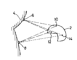
Referring to the drawing, a pilot's helmet 2 is
shown disposed within the cockpit 4. The cockpit carries
at least 2 DOAS 6,8 of the ~mirror-cube~ type already
described. On the helmet is mounted at least 3 LED
(light-emitting diode) light sources 10,12,14.
The LEDs emit spherical light waves which are sensed -~
by the DOAS. The size of the DOAS relative to their
distance from the LEDs is arranged to be sufficiently
small that, for practical purposes, each DOAS can be
considered to receive planar light waves from each LED.
The helmet is independent of the remainder of the ~ -
system and includes a battery power supply for the LEDs -
and for oscillators to tone modulate each LED at different
frequencies. The DOAS receive the tone modulated light
signals and discriminate between each LED by filtering the
received signals. From each discriminated isignal the
direction of arrival of the light beam (i.e. the direction
in space from the DOAS to the LED in question) may be
computed as described in the said copendinq patent
application.
In a perfect system, the position ~n space of any
one LED ought to be defined by the intersection of the
computed directions-of-arrival from two spaced-apart DOAS
to the LED. In practice, these lines may not exactly
coincide and it is convenient to choose, as the LED
position, the midpoint of the shortest line segment which
~oins two computed lines. With the poisitions in Qpace of
three separate LEDs having been determined, it is then a
simply trigonometric matter to translate these positions
into the orientation of the helmet in space, and to the
pilot's line of sight.
~, ~
I
- 5 ~
For greater accuracy, a larger number of DOAS and
LEDs may be employed. It is also possible to reverse the
positions of the LEDs and DOAS - so that the latter are
upon the heLnet. This is less practical as it is likely `;~
to necessitate connecting the helmet to the aircraft's `~
electronic systems. ~-`
With the apparatus of the invention it is possible ,`~
to determine not only the line of sight of the pilot
relative to the cockpit, but also the orientation of his -~
head about this line-of-sight. This latter information
may, in fact, not be necessary if, for example, the line
of sight is to be employed to fire a missile upon an
off-aircraft-axis trajectory.
,. . ,~ ,~ .,
``"``' i
'`,.`"`~` ',`'`~'.'.`
, `~'.', ' ~','
, .. .....
` .... `. -','`
`''",',,~ ~,.'
.`~.: ~.,.`
'',''" :''~.
; ., ,. ~ . :;