Note : Les descriptions sont présentées dans la langue officielle dans laquelle elles ont été soumises.
2~
ENGINE BREATHER ASSEMBLY
WITH OIL DRAI~ BACK
Background Of ~he Invention
I. Field of th_ Invention
~ his invention relates to a breather assembly for an
internal combustion engine and, in particular, to a brea~h~r
assembly which mounts to the crankca~e valve cover o~ the
engine and includ~s a drain back tube for returning
condensed oil to the crankca~e for more efficient operation
of the engine.
II Description of the Prior Art
.
Internal combus~ion engines reguire proper crankcase
ventilation for efficient operation. Crankca~e vapors are
in constant circulation and highly turbulent during engine
operation. The crankcase vapor includes oil which must be
separated from the vapor before vapor i~ released to the
atmosphere. In order to control the ventilation of the
crankcase a breather device is utilized to allow air to pass
into and out of the cra~kcase as pressure within the
crankcase changes during operation of the engine. However,
merely expelling the crankcase vapors results in
uneconomical operation since the oil within the vapor is
lost. Furthermore, the oil vapor will deposit on the
external parts of the engine and pollute the atmosphere.
Breath~r assemblies for past internal combustion
engines have included intricate baffling and filtering
mediums to condense and filter the oil from the vapor~
travelling through the breather. ~he prior Xnown breathers
included multiple baffle chambers through which the vapor
must travel and which cause the oil to condense within the
Z(~C)2~
breather. The liquid oil would therea~ter drip out of the
bottom of the brea~her back into the crankca~e~ Other
breathers use the filtering material to condense the oil
vapor which accumulates in the bottom of the breather
hou ing and drips back into the crankcase. The past kn~wn
assemblies depend upon a specific accumulation of oil before
it is returned to the crankcase.
Summary Of The Present Invention
The present invention overcomes the disadvantages of
the prior known breathers by providing a simple assembly
which is mounted to the ~alve cover of an internal
combustion engine and which includes a drain back tube
leading to a low pressure area of the crankcase which
creates a vacuum within the tube to draw the accumulated oil
back into the crankcase. As a result, accumulated oil does
not continue to mix with the incoming vapors.
The breather assembly according to the -present
inventio~ includes a housing which forms the baffled flow
passageway of the breather. The housing includes a stem
having an axial passageway and a cap mounted to the stem ko
~orm the circuitous flow path. The stem includes an annular
flange which includes threads to engage th~ cap and
circumferentially spaced exhaust ports through which the
engine vapors pass. The axial passageway through the stem
includes a restricted portion which facilitates condensation
of the oil as the vapors pass therethrough. The lower end
o~ the stem includes external threads for mounting the
breather to the valve cover. A check valve and drain back
tube are mounted within the passageway to allow the vapor to
flow into the breather assembly and returning condensed oil
to the crankcase, respectively4
Other objects, features, and advantages of the
invention will be apparent from th2 following detailed
..... . . . . .
.: - -
.. , , ~. . . ::
,: ... ~
.:.. , . ~ . . .
" .. .: ' ~,, ~ : . ;
.. . ... :
.,. :
-
Z~2~
d~scription taken in connection with the accompanying
drawings.
Brie* Description of the Drawin~
The present invention will be more fully understood by
reference to the following d2tailed description of a
preferred embodiment of the present invention wh~n read in
conjunction with the accompanyinq drawing, in which like
reference characters refer to like parts throughout the view
and in which:
FIGURE 1 is an elevated perspective of an internal
combustion engine haviny the breather assembly embodying the
present invention mounted to the valve cover of the engine;
FIGURE 2 is an exploded view of the breather assembly
embodying th~ present invention:
FIGURE 3 is a partial cross-sectional perspective of
the breather assembly with ~ check valve and drain back tube
mounted therein;
FIGURE 4 is a cross-sectional perspective of the
breather assembly embodying ~he present invention wi~hout
the check valve and drain back tube;
FIGURE 5 is a cross-sectional perspective of the
breather assembly taXen along line 5-5 of Fig. 4; and
FIGURE 6 is an end view of the breather assembly taken
along line 6-6 of Fig. 4.
Detailed DescriPtion Of A Preferred
Embodiment Of The Present Invention
Referring first to Figure 1, there is ~hown an internal
combustion engine 10 of the type used in oilfield
applications. The engine 10 has mounted there~o a breather
assembly 12 embodying the present invention. In a preferred
embodiment, the breather assembly 12 i mounted to the valve
or crankcase cover 14 of the engine 10 to vent gases from
: 3
.- : ~ . - : . ~ .:. . .. .. , -.
2~274~
the engine 10 providing efficient ventilation. The ~reather
assembly 12 is preferably threadably mounted within an
opening 16 in the valve cover 14. The breather assembly 1~
is adapted to ventilate gases from the crankcase while
causing oil vapor~ to condense tc liquid form prior to
expulsion of the gases through the assembly 12 resulting in
cleaner and more ef~icient operation o~ the engine 10.
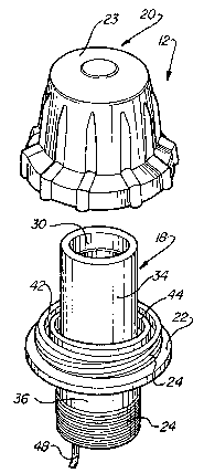
Referring now to Figures 2 through 6, the breather
assembly 12 generally comprises a substantially tubular stem
18 and a cap 20 mounted to the stem 18. The stem 18
includes an integral outer annular flange 22 ~ormed at
approximately the mid-point to the stem 18. The cap 20 has
a substantially domed con~iguration with a concave upper
wall 23. In a preferred embodiment, the stem 18 and cap 20
are molded ~rom a polyuxethane material. The ~lange 22 is
provided with threads 24 which engage matching threads 26 on
the cap 20 to secure the cap 20 to the annular flange 22 of
the stem 18. The lower end of the stem 18 is also provided
with threads 28 for mounting the breather assembly 12 within
the opening 16 of the valve cover 14.
The stem 18 has an axial fluid passageway 30 which
communicates with the interior of the engine 10. The axial
passageway 30 includes a re~tricted intermediate p~rt 32
which hac a smaller diameter than the diamPter o~ the axial
passageway 30. The restricted portion 32 i5 preferably
positioned approximately midway through the passageway 30
and facilitates condensation of the oil vapors as t~ey pass
through the passageway 30 as will be subsequently described.
Thus, the outer flange 22 and the restricted port 32 divide
the 6tem 18 into an upper ~ubular portion 34 and a lower
tubular portion 360 The upper tubular portion 34 of the
stem 18 ac~s as an upwardly extending baffle wall over which
the expulsion gases must pass pri~r to venting to the
atmosphere. When the cap 20 is mounted to the stem 18, the
.~: : , ~
: - ,~ , ' ~; .:, ~............ . :
2(~C)274~
baffle wall 34 extends almost to the domed upper wall 23 of
the cap 20. The domed configuration of the cap 30 will
direct expulsion gases radially outwardly and downwardly
into the annulus 38 formed between the ~ap 20 and the upper
tubular portion 3~ of the ~tem 18. The domed wall 23 also
facilitates ~urther cnndensation of the oil vapors.
The outer annular flange 22 include~ a plurality of
vent openings 40 circum~erentially spaced around the flange
22. The vent openings 40 allow fluid communication between
the annulus 38 and the exterior environment to expel the
engine vapors from the engine 10 and the breather assembly
12. The vent openings 40 are circumferentially spaced along
an outer annular groov~ 42 in the flange 22 which helps to
direct the gases through the openings 40. An inner annular
collection groove 44 will collect any oil which may condense
out o~ the vapor after passing over the ba~fle wall 34 into
annulus 38.
Referring now to Figure 3, in order to prevent air or
gas~s from passing through the breather assembly 12 into the
engine 10 and to return condensed oil back to the engine 10,
a check valve 46 and drain back tube 48 are mounted within
the lower tubular portion 36 of the stem 18. The lower end
of the stem 18 is provided with an annular shoulder 50 to
receive the check valve 46 and a notch 52 to receive the
drain back tube 48 in proximate location to the check valve
46. The drain back tube 48 is a simple, preferably
flexible, tube which provides fluid communication between
the axial fluid passageway 30 and a low pressure area of the
crankcase 14 such that condensed oil which collects in the
bottom of the pa~sageway 30 will be virtually sucked back
into the crankcase through the tube 48. The check valvP 46
includes. a valve housing 54 and ~ valve seat 56 between
which a Ivalving plate 58 is biased by a spring 60. The
spring 6,0 is disposed between the valve housing 54 and the
!
.-:: . . :: ~ . : : .
OZ740
valving plate 58 ~o as to bias the plate 58 against the
valve seat 56 to close the check valve 46. The valve
housin~ 5~ includes at least one port 62 through which the
engine vapors may pass into the axial fluid passageway 30.
Engine vapors expelled through the opening 16 in the valve
cover 14 ~ill ~low throuqh the aperture 64 of the valve seat
56 and mo~e the valving plate 58 against the force of the
spring 60 to open the check valve 46 and allow ~low into ~he
axial passageway 30. When a vacuum is created or the engine
is not running, the check valve 46 will close under the
force of the spring 60.
~ he breather asse~bly 12 of the present invention
allows the expulsion of engine vapors from the internal
combustion engine 10 while maintaining clean and economical
operation of the engine 10 by condensing oil from the vapors
and returning it to the engine crankcase 14. The oil-laden
engine vapors pass through the check valve 46 into the axial
fluid passageway 30 of the breather assembly 12. As the
vapors flow upwardly through the passageway 30 and the
restrictive port 32 oil will condense out of the vapors
against the inner walls and will flow to the bottom of the
stem 18. Virtually all of the oil will be condensed out of
the vapor~ by the time the vapors pass over the rim of the
baffle wall 34. The engine vapors will thereafter be
expelled through the vent openings 40 into the ~urrounding
atmosphere. Collected oil will flow through the drain ~ack
tube 48 into the engine 10. Thus, oil which may foul the
external components of the engine 10 or pollute the
atmosphere will be condensed from the expelled engine vapors
for re-use by the engine lO.
The foregoing detailed description has been given for
clearness of understanding only and no unnecessary
limitations should be understood t~erefrom as some
~odifications will be obvious to those skilled in the art
. ,
,, ., - . :
:' , : ~ .
. .: . ,., , ~ ,, .
-
- :-, .. :, . :
, . - ~:
2~274~)
without deparl:ing from thsi scope and spirit of the appended
claims .
I claim;
. - , ~ .-. . -.. ,. ~ . . ..