Note : Les descriptions sont présentées dans la langue officielle dans laquelle elles ont été soumises.
20~2911 PATENT
PD-88229
:. '' ': ~ ' .
'
A FIBER GUIDE WITH iADJUSTABLE
FIBiERiAPERTURE
BACKGROUND OF THE INVENTION
The present invention generally relates to a fiber
guide and, in particular, relates to such a fiber guide
having an adjustable fiber aperture.
In many instances, when a fiber is wound upon a
mandrel, for example, optical fibers are wound upon
mandrels and used as a communication lin~ between a
control station and a projectile, some form of an adhesive
is applied to the fiber to ensure that the windings upon
the mandrel are retained in the proper disposition.
At the present time, the adhesive is usually
applied by either one of two different techniques. One
technique is to apply, generally by spraying, adhesive
after each layer of fiber is wound. For example, when
each layer of optical fiber is completed, the adhesive is
sprayed upon that layer. ~ence, in this technique, the
optical fiber is wound without adhesi~e and the spraying
of the previou~ layer contribut~s to the position
retention of the subsequent layer. The spraying technique
has numerous drawbacks. In particular, the mandrel, and
hence the winding process, is stopped after each layer is
~ ~ ,., ' i ' . ` ' `~ ' ` ' ' ~ a I ~
~ ~r~
20029~1.
1 wound so that the adhesive can be sprayed on the exposed
layer. The mandrel is then incrementally rotated to apply
the adhesive completely upon the layer. Thus, the winding
time of a given mandrel is extended due to the need for
the stopping and incrementing. Another drawback of this
technique is that, regardless of various safeguards, the
adhesive is difficult to apply uniformly both along and
between each layer. Thus, when being unwound, the optical
fiber may not unwind smoothly and become damaged due to
the differing adhesive forces along the entire length
thereof.
Another technique for applying an adhesive to a
fiber being wound upon a mandrel is, effectively, both
pressureless and continuous. These types of techniques
substantially overcome the drawbacks of the spraying
techniques. However, other difficulties are encountered.
For example, the optical fiber, once winding has begun,
cannot be removed without breakage or considerable
difficulty. For example, if a flaw is found in the
optical fiber being wound it may have to be returned to
the manufacturer for repair. As another example, since
the adhesive is applied prior to the actual winding, if
the winding is interrupted the adhesive will dry and the
optical fiber can become glued in the winding mechanisms.
~;25 Currently, the more common apparatus utilizing this
i;adhesive application technique include fiber guides that
can be characterized as the tube/needle or the split die.
In the tube/needle fiber guide, the optical fiber
is threaded through the end of a needle that traps and
guides the optical fiber. Consequently, in order to
- remove the optical fiber, the optical fiber must either be
broken or completely drawn through the needle opening. If
the optical fiber is broke the fiber must thereafter be
spliced and thus, the communication and/or strength
characteristics thereof can be significantly reduced. If
. :: ,...
` 2~02911 ~ : ~
the optical fiber is drawn through the needle a substantial
amount of waste can occur. Further, the needle of such an
arrangement has a fixed opening and thus different
apparatus are required for differënt sizes of optical ~ '
fiber.
In the split die fiber guide the optical fiber is
secured between the members of the die and drawn
therethrough. However, the die assembly must be
disassembled everv time the optical fiber is to be removed
or the winding proces interrupted for an extended length -
of time. Further, the split die has a fixed opening and
thus, different dies are required for different sizes of
optical fiber. .
Thus, a fiber guide is needed that not only
allows removal of the fiber, without difficulty or
detriment thereto, at any time and enhances uniform
adhesive application but also includes an adjustable
aperture to better compensate for variations in fiber size.
SUMMAR~ OF ~HE INVENTION .~
Consequently, it is an object of an aspect of the -
present invention to provide a fiber guide that
; substantially overcomes the above-recited deficiencies of
current fiber guide~. -
This object is accomplished, at least in part, by
providing a fiber guide having, inter alia, first and
~; second members, each having notches for receiving a fiber.
The first and second members being disposed, in one
preferred embodiment, in a sleeve having a longitudinal
slot therein. The ~embers being disposed within the sleeve
such that, when the notches thereof are aligned with the -~
slot, a fiber can be removed from or placed into
the guide without disassembly of the guide or breaking the
fiber. Further, in the preferred embodiment, one of the -
members is rotatable such that the aperture between the
members i5 adjustable.
Other aspects of thi~ invention are as follows~
A fiber guide comprising:
- B :-:
,~ .
2 Q o 2 9 ~
a sleeve, said sleeve having a longitudinal opening : :
therealong, said opening being sized to allow a fiber to
pass therethrough; :
a first member fixed within said sleeve proximate a
first end thereof, said first member having a first
notch extending thereinto, said first notch being
substantially aligned with said longitudinal opening in ~:i`:~
said sleeve such that said fiber can be dispo6ed into
said first notch through said longitudinal opening; :~
a second member disposed within said sleeve, said
second member being rotatable within said sleeve and
having a second notch extending thereinto, said second
notch being alignable with said longitudinal opening
such that said fiber can be disposed into said second
notch through said longitudinal opening;
said first and second notches having end portions .
confronting one another at an interface; and
means for rotating said second member to
: selectively vary the size of an opening formed at said
interface between said first and second notches.
: A fiber winding apparatus comprises~
means for applying an adhesive to a fiber;
a mandrel, said mandrel being adapted to rotate;
and `~
~`~ means, di6posed between said adhesive applying
means and said mandrel, for guiding said fiber
therebetween, said fiber guiding means including:
a sleeve, said sleeve having a longitudinal opening ~:
therealong, said opening being sized to allow a fiber to
pass therethrough; ~::; :` . :
a first member fixed within said sleeve proximate a
first end thereof, said first member having a first ~u
:~ notch extending thereinto, said first notch being
:~ substantially aligned with said longitudinal opening in .
said sleeve such that said fiber can be disposed into ,~
said first notch through said longitudinal opening~
,~, ': , , .
~ B
~: 2a~2sll ~
4a
a second member disposed within said sleeve, said
second member being rotatable within said sleeve and
having a second notch extending thereinto, said second
notch being alignable with said lQngitudinal opening
such that said fiber can be disposed into said second
notch through said longitudinal opening;
said first and second notches having end portions
confronting one another at an interface; and
means for rotating said second member to
selectively vary the size of an opening formed at said
interface between said first and second notches.
Other objects and advantage6 of the present ;~
invention will become apparent from the following detailed
description read in conjunction with the claims appended
hereto and the attached drawings. ~
BRIEF DESCRIPTION OF THE DRAWINGS -
The drawings, not drawn to scale, includes:
FIGURE 1 a perspective view of a fiber guide
embodying the principles of the present invention;
FIGURE 2 is a cross-sectional view, taken along
the line A-A, of the fiber guide shown in FIGURE 1;
, ...
FIGURE 3 is a cross-sectional view, taken along
the line B-B, of the fiber guide shown in FIGURE l;
FIGURES 4a and 4d are cross-sectional views,
taken along the line B-B, of the fiber guide shown in
FIGURE 1 showing different aperture settings therefor; and
FIGURE 5 is a perspective view of an operating
environment for the fiber guide embodying the principles of
the present invention.
~TAI~ED DESCRIPTION OF THE INVENTION
~ . I I i .. ~ ~
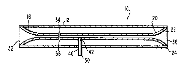
A fiber guide, generally indicated at 10 in
FIGURE 1 and embodying the principles of the present
invention, includes a sleeve 12 having a longitudinal
opening 14 therealong, a first member 16 fixed within the
sleeve 12 proximate a first end 18 of the sleeve 12. In ~ ;
addition, the fiber guide 10 includes a second member 20
rotatably disposed within the sleeve 12 and having one
end 22 -
'` ~E31
Z00;~91~ ~ ~
~ ,~"
1 thereof proximate the second end 24 of the sleeve 12.
Further, the first and second members, 16 and 20,
respectively, include a first and a ~econd notch, 26 and 28, ;~
respectively, therein. The first notch 26 of the first
member 16 is substantially aligned with the longitudinal
opening 14 of the sleeve 12. The fiber guide 10 also
includes a means 30 for rotating the second member 20
within the sleeve 12.
In one preferred embodiment, the sleeve 12 is
10 fabricated from a rigid material, such as, for example, `~
stainless steel tubing and has a length greater than about
an inch. Further, the sleeve 12, in this preferred
embodiment has an outside diameter of about one-quarter
(0.25~ of an inch and a wall thickness of about three one-
15 hundredths (0.03) of an inch. In one embodiment, the -~
longitudinal opening 14 is formed to a width about equal
to an arc that subtends about a forty degree angle.
In one preferred embodiment, the first member 16
includes first and second ends, 32 and 34, respectively,
and is fixed within the sleeve 12. Preferably, the first
end 32 of the first member 16 is disposed proximate the i ~ ;
first end 18 of the sleeve 12 with the first notch 26
aligned with the longitudinal opening 14. Preferably, the
first end 32 of the first member 16 is flared to about the
inside diameter of the sleeve 12. In such an embodiment,
the unflared diameter of the first member 16 is on the ~ `
order of about 0.012 of an inch. The first notch 26 of
the first member 16 is, preferably, on the order of about
20 degrees and includes a rounded bottom having a radius
of about the radius of an optical fiber, for example,
about 0.006 of an inch.
, ~ ,: ~ ~ . . .
. : .
' ~ `~' . ` ~.
, ~ -
`~` 2002911. -
1 In the preferred embodiment, the second member 20
includes first and second ends, 36 and 38, respectively,
and is disposed within the sleeve 12 with the first end 36
thereof proximate the second end 24 of the sleeve 12~ In
one such embodiment, the second end 38 of the second
member 20 abuts and is axially aligned with the second end
34 of the first member 16. Alternatively, the first and
second members, 16 and 20, can also be eccentrically
aligned to provide a preselected aperture. Further, the
notch 28 of the second member 20 is substantially
identical to the notch 26 formed in the first member 16.
Preferably, the first end 36 of the second member 30 is
also flared to approximate the inside diameter of the
sleeve 12 without restricting the rotation thereof.
15In this embodiment, the means 30 for rotating the
second member 20 within the sleeve 12 includes a handle 40
having one end 42 thereof affixed to the second member 20
and extending through a lateral slot in the sleeve 12. In
order to provide the maximum possible variation of the
fiber aperture through the first and second members the
lateral slot extends, in this embodiment, about 180
degrees about the periphery of the sleeve 12. Preferably,
the lateral slot is spaced apart from the longitudinal
opening 14 in the sleeve 12. Such an arrangement
maintains the structural strength of the sleeve 12.
`;As shown in FIGURE 3, the notches of the first and
second members are, in this embodiment, aligned and, since
both are provided with side radii and rounded at the
bottoms thereof, form an aperture through which an optical
fiber is guided. By rotating the second member 20, as
shown in FIGURES 4a-4d, the size of the aperture can be
; varied to accommodate various sized optical fibers. Pre-
ferably, in operation, the aperture is adjusted so that
~; 35
^` 2~)0~
.
7 -
,.: ~-., .
: : : ,-..... -..... :
1 excess adhesive is removed from the optical fiber prior to
the fiber being wound upon the mandrel. The operation of
the fiber guide lO is more fully discussed below with
respect to FIGURE 5. -
A typical operating environment wherein the fiber -~ ~
guide lO is particularly useful is shown in FIGURE 5. -
Therein the fiber guide lO is disposed between the
reservoir for retaining the adhesive and the mandrel being
wound. The optical fiber is drawn through the adhesive at -
a predetermined speed and is thereby coated with adhesive.
The optical fiber is then passed through the fiber guide
lO that, in addition to guiding the fiber to the mandrel,
removes excess adhesive prior to the optical fiber
reaching the mandrel being wound. `~
The fiber guide lO thus provides a wiping action -
that ensures that the adhesive is substantially uniformly
applied to the fiber as it reaches the mandrel. This
uniformity helps prevent damage to the optical fiber when
the fiber is drawn from the mandrel. Further, the optical
fiber can be removed, without damage, from the fiber guide
lO to enable correction of a flaw or as to allow extended
interruption of the winding procedure.
Although the present invention has been described ~ ;
herein with respect to a particular embodiment, those ~ -
skilled in the art will recognize that other
configurations and variations can be implemented without
departing from the spirit and scope hereof. Hence, the ;!
presaent invention is deemed limited only by the claims
appended hereto and the reasonable interpretation thereof.
, ,
~ ; `
: ~ : . . .: ::