Sélection de la langue

Search

Sommaire du brevet 2002937 

Énoncé de désistement de responsabilité concernant l'information provenant de tiers

Une partie des informations de ce site Web a été fournie par des sources externes. Le gouvernement du Canada n'assume aucune responsabilité concernant la précision, l'actualité ou la fiabilité des informations fournies par les sources externes. Les utilisateurs qui désirent employer cette information devraient consulter directement la source des informations. Le contenu fourni par les sources externes n'est pas assujetti aux exigences sur les langues officielles, la protection des renseignements personnels et l'accessibilité.

Disponibilité de l'Abrégé et des Revendications

L'apparition de différences dans le texte et l'image des Revendications et de l'Abrégé dépend du moment auquel le document est publié. Les textes des Revendications et de l'Abrégé sont affichés :

  • lorsque la demande peut être examinée par le public;
  • lorsque le brevet est émis (délivrance).
(12) Brevet: (11) CA 2002937
(54) Titre français: APPAREIL DE MESURE DU CARROSSAGE, DE LA CHASSE, L'INCLINAISON DE L'AXE DE PIVOTEMENT D'UN VEHICULE
(54) Titre anglais: APPARATUS FOR MEASURING CAMBER, CASTER AND STEERING AXIS INCLINATION OF A VEHICLE
Statut: Périmé et au-delà du délai pour l’annulation
Données bibliographiques
(51) Classification internationale des brevets (CIB):
  • G01D 21/00 (2006.01)
(72) Inventeurs :
  • WICKMANN, JOHN T. (Canada)
  • CARLTON, PHILLIP (Canada)
(73) Titulaires :
  • CHASSIS LINER CORPORATION
(71) Demandeurs :
  • CHASSIS LINER CORPORATION (Etats-Unis d'Amérique)
(74) Agent: GEORGE A. ROLSTONROLSTON, GEORGE A.
(74) Co-agent:
(45) Délivré: 1994-06-21
(22) Date de dépôt: 1989-11-14
(41) Mise à la disponibilité du public: 1991-05-14
Requête d'examen: 1994-06-21
Licence disponible: S.O.
Cédé au domaine public: S.O.
(25) Langue des documents déposés: Anglais

Traité de coopération en matière de brevets (PCT): Non

(30) Données de priorité de la demande: S.O.

Abrégés

Abrégé anglais


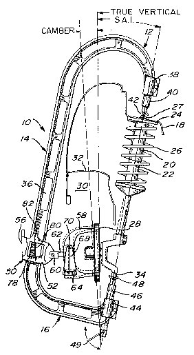
ABSTRACT OF THE DISCLOSURE
The disclosure herein describes an apparatus
that enables simultaneous readings of the camber,
caster and steering axis inclination of the steering
components of a front wheel suspension of a vehicle;
the apparatus comprises a C-shaped upright, the upper
and lower extremities of which engage the upper and
lower steering pivots of the component. A carriage,
slidably mounted on the upright, supports a yoke member
which is adapted to bear against the hub assembly of
the vehicle wheel. A first gauge is mounted to the
yoke member to give a camber reading of the strut while
second and third gauges are mounted on the carriage to
give a caster reading and a steering axis inclination
reading.

Revendications

Note : Les revendications sont présentées dans la langue officielle dans laquelle elles ont été soumises.


11
The embodiments of the invention in which an
exclusive property or privilege is claimed are defined
as follows:
1. An apparatus for enabling simultaneous
readings of the camber, caster and steering axis
inclination of steering components that form part of a
front wheel suspension of a vehicle equipped with a hub
assembly, the steering components including upper and
lower steering pivots defined along a steering axis;
said apparatus comprising:
- an upright having an upper part and a
lower part;
- first engaging means at said upper part
adapted to engage said upper steering pivot;
- second engaging means at said lower part
adapted to engage said lower steering pivot;
- third engaging means having a first part
adjustably mounted on said upright and a
second part adapted to bear against said hub
assembly;
- first gauge means mounted on said second
part for giving a camber reading of the hub
assembly;
- second gauge means mounted on said

12
upright for giving a caster reading of the
steering axis; and
- third gauge means mounted on said
upright for giving a steering axis
inclination reading.
2. An apparatus as defined in claim 1,
wherein said first part of said third engaging means
consists of a carriage slidably mounted on said
upright.
3. An apparatus as defined in claim 2,
wherein said second part of said third engaging means
is pivotally and adjustably mounted to said carriage.
4. An apparatus as defined in claim 3,
wherein said second part of said third engaging means
consists of a yoke member having its free extremities
adapted to contact said hub assembly.
5. An apparatus as defined in claim 1,
wherein said first gauge means consist of a graduated
scale displayed on said second part of said third
engaging means and of an indicator pointer freely
suspended in front of said scale.

13
6. An apparatus as defined in claim 2,
wherein said second gauge means consist of a graduated
scale displayed on a first side wall of said carriage
and of an indicator pointer freely suspended in front
of said scale.
7. An apparatus as defined in claim 6,
wherein said third gauge means consist of a graduated
scale displayed on a second side wall of said carriage
and of an indicator pointer freely suspended in front
of said scale.
8. An apparatus as defined in claim 1,
wherein said upright is C-shaped, the extremities of
the upper and lower parts thereof each carrying said
means for engaging the upper and lower steering pivots.
9. An apparatus as defined in claim 8,
further comprising spring-loaded means mounted on said
lower part of said upright for tightly securing said
upper and lower parts to said steering components when
engaged thereon.
10. An apparatus as defined in claim 1,
wherein said steering components are McPherson-type
struts.

Description

Note : Les descriptions sont présentées dans la langue officielle dans laquelle elles ont été soumises.


; ::
2002937 :
.. .
. . .
FIELD OF THE INVENTION
The present invention relates to an apparatus ~ ~;
for assisting in the repair of damaged vehicles. More ~ ;
particularly, the invention relates to an apparatus
5that enables simultaneous readings of the camber, ~;
caster and steering axis inclination (S.A.I.) of
steering components that form part of the front wheel
suspension of a vehicle. Furthermore, the invention is
particularly relevant to vehicles equipped with
10McPherson-type strut assemblies. ; ~
'~ '. .' ~,:
BACRGROUND OF THE INVENTION
The front suspension system and supporting -
structures of a damaged vehicle must be checked to
determine the real positions of the struts or other
.~
i 15steering components with respect to the axle with a
view to correcting any misalignment of struts or
components that do not conform to specifications.
Three values must be examined in order to
effect a correct alignment: the caster, the camber and
20the steering axis inclination. The caster is the
angular relationship between the upper steering pivot
and the lower steering pivot defined along the steering
axis as viewed from the side of the vehicle; caster is
~`~ measured in degrees from true vertical. The camber is
: ~

r~ 2002937
- 2 -
the inward or outward tilt of the wheel as viewed from
the front of the vehicle; camber is measured in degrees
from true vertical. The steering axis inclination is
the angle of an imaginary line through the upper
steering pivot and the lower steering pivot of the
steering axis as viewed from the front of the vehicle;
this inclination is measured in degrees from true
vertical.
Strut alignment gauges exist. For example,
10 U.S. patent no. 4,453,315 issued June 12, 1984 to
Mosiman et al, no. 4,4g8,242 issued February 12, 1985
to Celette and no. 4,640,015 issued February 3, 1987 to
Mason all describe various types of gauges for
measuring the displacement of automobile components
with particular emphasis on the checking of the angular
disposition of McPherson-type struts. The apparatus
described in these patents allow the measurement of one
or more of angles, such as camber, caster, toe-in and
alignment. None, however, pertains to an apparatus
which will measure the steering axis inclination and
none enables the simultaneous measurements of caster,
camber and steering axis inclination.
,~; OBJECTS AND STATEMENT OF Tn~ INVENTION
It is an object of the present invention to
provide an apparatus that will allow simultaneous
~ "'''''','",''`";~

~, 200X93~ :
. . , ' ' --:
- 3 - - -
readings of the camber, caster and steering axis ;
inclination of a vehicle's steering component. This is
achieved by accurately positioning the apparatus to the
upper and lower steering pivots of the steering axis. ~ -
" ' '~,
5To this end, the apparatus of the present
invention, therefore, comprises: an upright having an
. , -
upper part and a lower part; first engaging means at
the upper part adapted to engage the upper steering
pivot; second engaging means at the lower part adapted
10to engage the lower steering pivot; third engaging
means having a first part adjustably mounted to the
upright and a second part adapted to bear against the
, ~ , . vehicle hub assembly; first gauge means mounted on the
~ second part for giving a camber reading of the hub
i~ 15assembly; second gauge means mounted on the upright for
giving a caster reading of the steering axis; and third
'!''j'~ gauge means mounted on the upright for giving a
steering axis inclination reading of the steering axis. ~ ~ ~
":
`In one preferred form of the invention, the
gauge means each consist of a graduated scale and of an
indicator pointer which is freely suspended in front of
the scale to give the respective readings.
In another form of the invention, the first -
~part of the third engaging means consists of a carriage
: `
.,.
. ' :::
-'~: ' ' ~:' .:.

`^ ~00293
- 4 - ~-~
slidably mounted on the upright while the second part ;~
is a yoke pivotally mounted to the carriage and
longitudinally adjustable relative thereto to be
positioned accurately against the brake rotor plate.
Other objects and further scope of ~;
applicability of the present invention will become
apparent from the detailed description given ;~
hereinafter. It should be understood, however, that
this detailed description, while indicating preferred ;~
embodiments of the invention, is given by way of
illustration only, since various changes and
~- modifications within the spirit and scope of the
invention will become apparent to those skilled in the
art. `; `
IN THE DRAWINGS -~
:, ,. . ~ . ~ .:. .,
; Figure 1 is a side elevational view of the
apparatus of the present invention shown mounted to the
upper and lower steering pivots of a McPherson~type
strut;
Figure 2 is a front elevational view of the
apparatus shown in figure l;
Figure 3 is an enlarged side view of the
~ '``''' :'"'.'.

~ 200;~937
-- s --
::
lower part of the upright as seen from the left of
figure 2; and
Figure 4 is an elevation view showing the
apparatus of the present invention mounted on a
vehicle.
DESCRIPTION OF PREFERRED EMBODIMENTS
Referring to figure 1, the apparatus of the
present invention comprises a C-shaped upright 10
including a curved upper part 12, a straight
intermediate part 14 and a curved lower part 16. The
~i upright is shown mounted to a conventional vehicle
steering component, such as a McPherson-type strut,
which provides spring suspension for a wheel assembly.
The strut is mounted to and within fixed strut towers
18, which are also referred to as the front inner sheet
metal of the vehicle. The strut comprises two
telescopic tubes 20 and 22, the outer tube carrying a
seat or bearing plate 24 against which bears a coil
spring 26. The vehicle front wheel (not shown) is
. ~
attached to a hub assembly that includes a brake rotor -
disc plate 28 within the vehicle wheel well 30 defined
by a mud-guard 32. The lower end of the strut is the
lower steering pivot which is represented by reference
numeral 34 and is, in most cases, a lower ball joint.
".

~ 2 0 ~ 2 9 3 7 ~ ~ ~
. .....
- 6 ~
The upright 10 is I-shaped in cross-section,
the inner face of which displays a series of elongated
openings 36 to reduce weight. The upper part 12
includes a cylindrical bracket 38 for mounting an -~
upper locator 40 displaying a cup-shaped extremity 42
for engaging the upper projecting bolt 27 of the top
plate 24 of the strut. The lower part 16 of the
upright also includes a cylindrical bracket 44 for -
mounting a spring-loaded locator 46 having a cup~
shaped extremity 48 to engage the lower ball joint 34 ,` -y
of the strut. A lever 49 is used to lock the lower
locator as described below. : ~ `
Adapted to slide along the intermediate
portion 14 of the upright is a carriage 50 having
opposite side walls 52 and 54 (figure 2) and a front ~ ' '''`'Sr
wall 56. Referring to figure 3, a lead screw 53
enables the vertical displacement of the carriage
along the intermediate portion 14 of the upright while
a lock screw 55 secures the carriage in the desired ~ ;
vertical position.
A C-shaped yoke 58 with fingers 59 and 61 is
pivotally mounted at 60 to the inner side of the i~
carriage 50. This member 58 is longitudinally
adjustable relative to the carriage through the use of -~
a lead screw 62. A lock screw 63 secures the yoke in ,i ;~
~' ~:~'''', ,`
; . : , - ~

-
2002937
.
the desired angle relative to the upright. The upper
and lower fingers 59 and 61 of the yoke are adapted to .
contact the outer face of the rotor plate 28 by ~ :
adjusting the lead screw 62. ~ ¦~
'.
A first gauge is mounted on the yoke member
58 for providing a reading of the camber of the hub
assembly; it consists of a scale 64 and of a pointer 68
which is freely suspended from its upper pivot axis 70
(see figure 1). ~:
A second gauge for measuring the caster of :
the steering axis is provided on the front wall 56 of
-~ the carriage 50 and consists of a scale 72 and of a ~ ¦ -
,~ pointer 74 which is freely suspended from its upper ~ .
pivot axis 76 (see figure 2). ~ -
,,:: . ,:. .
A third gauge is provided on the carriage 50
for measuring the steering axis inclination and ;~
consists of a scale 78 and of a pointer 80 which is : .
l ` freely suspended from its upper pivot axis 82.
I
'' 1 1~
As illustrated in figures 1 and 2, the .~.
measurement of the caster, camber and the steering axis `~
inclination is always done with respect to a true ~ -
vertical. ~ .
I " ~
i ; ~
,~ .
. ..

2 ~ 3 7
- 8 -
As illustrated in figure 4, the measuring
apparatus 10 is mounted to a vehicle 90 which is
supported over a rack or base 92 by means of a series
of stands 94. However, since measurement is
accomplished simply through the movements of pointers
68, 74 and 80 acting under gravity, the vehicle must
be levelled in order to obtain accurate readings. To
~ . :. . . ,~`
achieve this, ride height must first be established
before mounting the vehicle on the stands 94; ride
height is measured from the center of wheel spindle to
a point on the vehicle body; if the body is badly
damaged, it is measured from the rack (or floor) to
the spindle center. A further measurement is made
from the underbody structure of the vehicle to the
rack (or floor) on all four corners of the vehicle.
The vehicle is then mounted on the anchor stands 94.
A measurement is made from the underbody structure of
the vehicle to the rack (or floor) while the vehicle
is mounted on the stands. Once correct measurements
have been established on all four corners of the
vehicle, anchor clamps 96 are tightened. Using a jack
or other lifting device, the suspension is raised by
compressing the strut until the correct ride height
;~ 25 dimension is established.
~ ,'', ' .",'''"''''"'.
~i The operation of the apparatus of the
~; present invention may now be used.
.~ A

,~ 200X93~ ~
. . .
g
The lock lever 49 is positioned such as the
lower locator 48 retracts into the shaft 46. The ;
upright is then positioned by placing the top locator
42 onto the center bolt 27 of the strut. The extremity
of the lower locator 48 is then slid up until it
contacts the lower ball joint 34. The lock lever 49 is
again actuated so as to extend the spring loaded
locator 48 to preload the apparatus securely to the -
strut. The camber yoke 58 is pivoted to read ~
approximately 0 degree. The lock screw 55 is loosened ~ ~ -
and the carriage 50 is positioned to the approximate ~ ~
center of the rotor plate 28 by manually operating the ~ ¦
-~ lead screw 53; then, the lock screw 55 is secured.
Then, the camber lock screw 63 is loosened and the yoke
is moved towards the rotor plate by turning the lead
screw 62. When the yoke touches the plate, it is
~ pivoted until both fingers 59 and 61 contact the rotor
'~ plate. The lock screw 63 is tightened locking the
yoke. An accurate reading of the camber, caster and
~;~ 20 steering axis inclination can be made and compared to i~
measurements found in manuals.
Although the invention has been described
above with respect to one specific form, it will be
evident to the person skilled in the art that it may be
modified and refined in various ways. It is therefore
wished to have it understood that the present invention
,~

ZQOX93
- 10 -
should not be limited in scope, except by the terms of
the following claims. ~ ;~
~''''` ',.
'~ . " ' . .,.:
' '.. "''''',~''',`","'''
,i~ , ,. . ~.
'""'",
'.,'.'..,,' ;:
";:
~l - i;' '-
~ "

Dessin représentatif
Une figure unique qui représente un dessin illustrant l'invention.
États administratifs

2024-08-01 : Dans le cadre de la transition vers les Brevets de nouvelle génération (BNG), la base de données sur les brevets canadiens (BDBC) contient désormais un Historique d'événement plus détaillé, qui reproduit le Journal des événements de notre nouvelle solution interne.

Veuillez noter que les événements débutant par « Inactive : » se réfèrent à des événements qui ne sont plus utilisés dans notre nouvelle solution interne.

Pour une meilleure compréhension de l'état de la demande ou brevet qui figure sur cette page, la rubrique Mise en garde , et les descriptions de Brevet , Historique d'événement , Taxes périodiques et Historique des paiements devraient être consultées.

Historique d'événement

Description Date
Le délai pour l'annulation est expiré 2006-11-14
Lettre envoyée 2005-11-14
Lettre envoyée 2002-09-23
Inactive : Correspondance - Transfert 2002-07-29
Inactive : Lettre officielle 2002-07-02
Inactive : TME en retard traitée 2001-11-13
Exigences relatives à la révocation de la nomination d'un agent - jugée conforme 2001-10-26
Inactive : Lettre officielle 2001-10-26
Exigences relatives à la nomination d'un agent - jugée conforme 2001-10-26
Lettre envoyée 2001-10-23
Inactive : Lettre officielle 2001-10-23
Lettre envoyée 2001-10-23
Lettre envoyée 2001-10-22
Inactive : Lettre officielle 2001-09-12
Demande visant la révocation de la nomination d'un agent 2001-08-27
Demande visant la nomination d'un agent 2001-08-27
Demande visant la révocation de la nomination d'un agent 2001-08-27
Demande visant la nomination d'un agent 2001-08-27
Inactive : Lettre officielle 2000-12-12
Lettre envoyée 2000-11-14
Inactive : Lettre officielle 1999-11-24
Accordé par délivrance 1994-06-21
Exigences pour une requête d'examen - jugée conforme 1994-06-21
Toutes les exigences pour l'examen - jugée conforme 1994-06-21
Demande publiée (accessible au public) 1991-05-14

Historique d'abandonnement

Il n'y a pas d'historique d'abandonnement

Historique des taxes

Type de taxes Anniversaire Échéance Date payée
TM (brevet, 8e anniv.) - générale 1997-11-14 1997-11-13
TM (brevet, 9e anniv.) - générale 1998-11-16 1998-11-05
TM (brevet, 10e anniv.) - générale 1999-11-15 1999-10-29
TM (brevet, 11e anniv.) - générale 2000-11-14 2000-11-24
Annulation de la péremption réputée 2000-11-14 2000-11-24
Enregistrement d'un document 2001-06-07
Enregistrement d'un document 2001-07-30
TM (brevet, 12e anniv.) - générale 2001-11-14 2001-11-13
Enregistrement d'un document 2002-04-25
TM (brevet, 13e anniv.) - générale 2002-11-14 2002-11-13
TM (brevet, 14e anniv.) - générale 2003-11-14 2003-11-03
TM (brevet, 15e anniv.) - générale 2004-11-15 2004-10-18
Titulaires au dossier

Les titulaires actuels et antérieures au dossier sont affichés en ordre alphabétique.

Titulaires actuels au dossier
CHASSIS LINER CORPORATION
Titulaires antérieures au dossier
JOHN T. WICKMANN
PHILLIP CARLTON
Les propriétaires antérieurs qui ne figurent pas dans la liste des « Propriétaires au dossier » apparaîtront dans d'autres documents au dossier.
Documents

Pour visionner les fichiers sélectionnés, entrer le code reCAPTCHA :


Pour visualiser une image, cliquer sur un lien dans la colonne description du document. Pour télécharger l'image (les images), cliquer l'une ou plusieurs cases à cocher dans la première colonne et ensuite cliquer sur le bouton "Télécharger sélection en format PDF (archive Zip)" ou le bouton "Télécharger sélection (en un fichier PDF fusionné)".

Liste des documents de brevet publiés et non publiés sur la BDBC .

Si vous avez des difficultés à accéder au contenu, veuillez communiquer avec le Centre de services à la clientèle au 1-866-997-1936, ou envoyer un courriel au Centre de service à la clientèle de l'OPIC.


Description du
Document 
Date
(aaaa-mm-jj) 
Nombre de pages   Taille de l'image (Ko) 
Revendications 1997-09-16 3 258
Abrégé 1997-09-16 1 67
Dessins 1997-09-16 2 142
Dessins représentatifs 2000-02-24 1 24
Description 1997-09-16 10 721
Avis de rappel: Taxes de maintien 2000-08-14 1 119
Avis concernant la taxe de maintien 2000-12-11 1 178
Deuxième avis de rappel: taxes de maintien 2001-05-14 1 118
Avis de rappel: Taxes de maintien 2001-08-14 1 131
Quittance d'un paiement en retard 2001-11-26 1 171
Avis concernant la taxe de maintien 2006-01-08 1 172
Taxes 2001-08-19 3 108
Taxes 2001-11-12 1 33
Taxes 2003-11-02 1 32
Correspondance 1999-11-23 1 6
Correspondance 2001-09-26 3 88
Correspondance 2001-08-26 5 130
Taxes 1997-11-12 1 48
Taxes 2000-11-23 4 133
Correspondance 2001-10-22 1 15
Taxes 1998-11-04 1 50
Correspondance 2001-10-22 1 14
Correspondance 2002-07-01 1 22
Taxes 2002-11-12 1 36
Correspondance 1999-11-23 1 8
Taxes 1999-10-28 1 107
Taxes 2004-10-17 1 34
Taxes 1996-11-06 1 34
Taxes 1994-09-28 1 31
Taxes 1995-10-12 1 33
Taxes 1991-10-31 1 24
Taxes 1992-10-29 1 26
Taxes 1993-10-26 1 26
Correspondance reliée au PCT 1999-10-28 1 38
Correspondance reliée au PCT 1994-03-28 1 26
Correspondance de la poursuite 1993-08-11 2 51
Courtoisie - Lettre du bureau 1990-04-29 1 21
Demande de l'examinateur 1993-02-22 1 56