Sélection de la langue

Search

Sommaire du brevet 2003086 

Énoncé de désistement de responsabilité concernant l'information provenant de tiers

Une partie des informations de ce site Web a été fournie par des sources externes. Le gouvernement du Canada n'assume aucune responsabilité concernant la précision, l'actualité ou la fiabilité des informations fournies par les sources externes. Les utilisateurs qui désirent employer cette information devraient consulter directement la source des informations. Le contenu fourni par les sources externes n'est pas assujetti aux exigences sur les langues officielles, la protection des renseignements personnels et l'accessibilité.

Disponibilité de l'Abrégé et des Revendications

L'apparition de différences dans le texte et l'image des Revendications et de l'Abrégé dépend du moment auquel le document est publié. Les textes des Revendications et de l'Abrégé sont affichés :

  • lorsque la demande peut être examinée par le public;
  • lorsque le brevet est émis (délivrance).
(12) Demande de brevet: (11) CA 2003086
(54) Titre français: DEVIDOIR POUR ASPIRATEUR CENTRAL
(54) Titre anglais: HOSE REEL FOR CENTRAL VACUUM CLEANING SYSTEM
Statut: Réputée abandonnée et au-delà du délai pour le rétablissement - en attente de la réponse à l’avis de communication rejetée
Données bibliographiques
Abrégés

Abrégé anglais


EU-334
ABSTRACT OF THE DISCLOSURE
A portable hose reel for a central vacuum cleaning
system with a pair of spaced discs connected by an axle for
winding the hose thereon. One of the discs is provided with a
hole which accomodates a rigid connector for the hose. The
connector additionally functions as a crank handle. The reel
has a stand which can be used as a carrying handle and as a
hanger element for the hose reel.

Revendications

Note : Les revendications sont présentées dans la langue officielle dans laquelle elles ont été soumises.


EU-334 (CAN)
The embodiments of the invention in which and exclusive
property or privilege is claimed is defined as follows:
1. A combination portable hose reel and a hose, said
reel having an axle for winding a length of said hose there-
on for a central vacuum cleaning system comprising: a pair
of spaced flange on said axle, one of said flanges having a
hole therethrough, said hose having a rigid connecting mem-
ber at one end passing through the hole in said one flange
whereby said member projects outside said one flange and
comprises a crank means for rotating the reel to wind the
hose on the axle thereof.
2. A combination portable hose reel and a hose, said
reel having an axle for winding said length of hose thereon
for a central vacuum cleaning system comprising: a pair of
spaced flanges on said axle, a stand for said hose reel con-
nected to said axle being so configured as to additionally
function as a carrying handle for said hose reel, one of
said flanges having a hole therethrough, and said hose hav-
ing a rigid connecting member at one end passing through the
hole in said one flange whereby said member projects outside
said one flange and comprises a crank means for rotating the
reel to wind the hose on the axle thereof.
3. A portable hose reel as claimed in claim 1 further
comprising a resilient member having one end connected to
the other end of said hose and the other end of said
-6-

EU-334 (CAN)
resilient member being removably connected to an edge of one
of said flanges.
4. A portable hose reel as claimed in claim 3 wherein
said resilient member is a coil spring.
5. A portable hose reel as claimed in claim 2 wherein
said stand is provided with floor-engaging legs extending in
a plane parallel with the plane of said flanges and an in-
termediate part funchioning as a carrying handle connected
between said legs and extending substantially perpendicular
thereto.
-7-

Description

Note : Les descriptions sont présentées dans la langue officielle dans laquelle elles ont été soumises.

EU-334 (CAN)
HOSE RE ~
The present invention relates to a central vacuum clean-
ing system and more particularly to a hose reel for trans-
porting an approximately 30-35 foot hose length from room to
room in a house or building equipped with a central vacuum
system, as well as storing the hose in a minimum of space.
A central vacuum system is well known which has a main vacu-
um apparatus, such as the motor housing, and a dirt recep-
tacle mounted in a centralized area of the building. The
main un~t is connected to the various rooms in the building
wlth ar air-tight, riyid tuhing system which is generally
concealed within the walls of the building. The tubing for
each room terminates with a special wall mount hose recep-
tacle to which a flexible hose is attached for vacuuming the
various rooms in the building. Of course, the flexible hose
is connected at one end to various cleaning attachments
while the other end is inserted into the vacuum wall recep-
tacle. Consequently, the coupling between the flexible hose
and the rigid tubing of the central vacuum system creates an
air- tight seal between the hose end and the wall recep-
tacle. A switch mechanism is employed to activate the n
motor in the main vacuum system, thus creating a suction for
vacuuming the various rooms in the building.
It is a principle feature of the present invention to
overcome the problem of storing and transporting the lengthy

7~(,
EU- 3 3 4 ( CAN
f]exible hose that is required in central vacuum systems~
Because of the e~traordinary length of the hose and the
rather large diameter of the hose itself, the usual coiling
arrangement of vacuum cleaner hoses employed on smaller
portable cleaning devices is not applicable to a central
vacuum system. ~onsequently, the movement of this lengthy
hose without kinkin-3, as well as uncoiling, presents a dif-
ficult task to the ordinary user. Furthermore, the trans-
port of the central vacuum system hose from room to room
also is difficult.
The present invention overcomes the problem of both
transport of the lengthy flexible hose as well as storage.
n the case of the latter, the present arrangement permits
the hose to be coiled on a reel in a simple and rapid manner
and hung on a hook or other projection on the wall of the
closet, thus taking up a minimum of space in the closet.
A further feature of the present invention is to provide
a means for preventing the user from uncoiling by accident
after it has been coiled on the reel.
Another feature of the present invention is to provide
spaced discs or flanges forming a reel in which one of the
flanges is provided with an opening through which a rigid
hose connector end is placed therethrough and thereby can
function as a handle for cranklng the reel, and at the same
time functions as a securement for on~ end of the hose.
It is a further object of the present invention to pro-
vide a vacuu~ cleaner hose reel which is light in weight,
and inexpensive to manufacture, and is provided ~ith a stand
--2--

;30~
EU-334 (CAN)
which also functions as both a handle and a support member
for hanging the hose reel on the wall o-f a closet.
In order that the present invention will be more clearly
understood, it will now be disclosed in greater detail with
reference to the accompanying drawings in which:
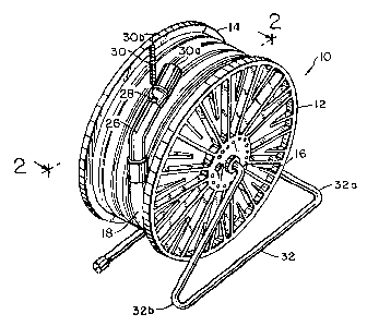
Fig. 1 is a perspective view of the hose reel and hose
for the central vacuum system constructed in accordance with
the teachings of the present invention.
Fig. 2 is a side elevational view taken along the lines
2-2 of Fig. 1.
Fig. 3 is a front elevation view thereof with a few
turns of the vacuum hose on the axle of the reel.
Fig. 4 is an enlarged par~ial sectional view of the hose
reel alone.
Fig. 5 is a side elevational view similar to that shown
in Fig. 2 with assembly suspended from a wall hook, and
Fig~ 6 is a perspective view of the hose reel and hose
being transported by the user.
DESCRIPTION OF THE PREFERRED EMBODIMENT
A central vacuum cleaner system (not shown), which is
permanently in place in a building is provided with a hose
reel referred to generally by the reference numeral 10 is
that includes spaced discs or ~langes 12 and 14 which may be
fabricated of plastic, metal or any other suitable material,
and has a central axle 16 about which the lengthy vacuum
cleaner hose 1~ is adapted to be turned or coiled. As seen
--3--

3~
EU-334 (CAN)
in Figs. 2, 3 and 5 the hose reel flange 14 is provided with
an opening 20 through which the end of the hose connected to
the vacuum wall receptacle (not shown) is passed through.
It should be evident that the end of the vacuum hose 18
passing through the opening 20 in a circular disc 14 is pro-
vided with a rigid tubular connection 2~, preferably fabri-
cated of metal, for separate coupling to various vacuum wall
receptacles in the building. rrhe tubular connection 22 i8
provided with an enlarged collar 24 for preventing the
tubular connection 22 from being detached from the circular
flange 14. The rigid tubular connection 22, as seen in
Figs. 2, 3 and 5, function6 as a crank handle for the reel
10, so that by operating the same when the hose length is
extended form the reel it can be coiled bac~ on the reel by
grasping the connection end 22 and turning the same thereby
rotating the reel 22. As seen in Fig. 1, the opposite end
of the vacuum hose 18 has another tubular connector 26, also
preferably fabricated of metal, for attachment to a variety
of cleaning tools for vacuuming a buildin~ or other struc-
ture. The tubular connector 25 is provided with an opening
28 in which an end 30a of the spring 30 is connected while
the other end 30b of the spring 30 is removably attached to
the edge of the disc 14 of the hose reel. This arrangement
has the desirable result of preventing the hose 18 from
being inadvertently unwrapped from the hose reel.
The hose reel 10 is rotatably supported by means of a
stand 32. It should be noted from Figs. 5 and 6 that the
stand 32 id provided with a looped handle part for the pur-
--4--

3~
EU--334 (CAN)
pose of transporting the lengthy hose reel from place to
place, as shown in Fig. 6, and also additional functions to
store the same on a wall-mounted hanger 34, as shown in Fig.
5. Conse~uently, the portion 32a of the mounting st~nd 32
functions as a carrying handle while the portion 32b of the
mounting stand functions as a catch or support for suspend-
ing the hose reel on a wall in a building, such as a closet.
While the invention has been disclosed and illustrated
in connection with a single embodiment thereof, it will be
apparent that other variations and modification may be made
therein, and it is intended in the following claims to cover
each such variation and modification which falls within the
true spirit and scope of the invention.

Dessin représentatif
Une figure unique qui représente un dessin illustrant l'invention.
États administratifs

2024-08-01 : Dans le cadre de la transition vers les Brevets de nouvelle génération (BNG), la base de données sur les brevets canadiens (BDBC) contient désormais un Historique d'événement plus détaillé, qui reproduit le Journal des événements de notre nouvelle solution interne.

Veuillez noter que les événements débutant par « Inactive : » se réfèrent à des événements qui ne sont plus utilisés dans notre nouvelle solution interne.

Pour une meilleure compréhension de l'état de la demande ou brevet qui figure sur cette page, la rubrique Mise en garde , et les descriptions de Brevet , Historique d'événement , Taxes périodiques et Historique des paiements devraient être consultées.

Historique d'événement

Description Date
Demande non rétablie avant l'échéance 2000-01-10
Inactive : Morte - Taxe finale impayée 2000-01-10
Réputée abandonnée - omission de répondre à un avis sur les taxes pour le maintien en état 1999-11-16
Réputée abandonnée - les conditions pour l'octroi - jugée non conforme 1999-01-11
Un avis d'acceptation est envoyé 1998-07-10
Lettre envoyée 1998-07-10
Inactive : Dem. traitée sur TS dès date d'ent. journal 1998-07-06
Inactive : Renseign. sur l'état - Complets dès date d'ent. journ. 1998-07-06
Inactive : Approuvée aux fins d'acceptation (AFA) 1998-05-22
Exigences pour une requête d'examen - jugée conforme 1995-10-02
Toutes les exigences pour l'examen - jugée conforme 1995-10-02
Demande publiée (accessible au public) 1991-05-16

Historique d'abandonnement

Date d'abandonnement Raison Date de rétablissement
1999-11-16
1999-01-11

Taxes périodiques

Le dernier paiement a été reçu le 1998-10-06

Avis : Si le paiement en totalité n'a pas été reçu au plus tard à la date indiquée, une taxe supplémentaire peut être imposée, soit une des taxes suivantes :

  • taxe de rétablissement ;
  • taxe pour paiement en souffrance ; ou
  • taxe additionnelle pour le renversement d'une péremption réputée.

Veuillez vous référer à la page web des taxes sur les brevets de l'OPIC pour voir tous les montants actuels des taxes.

Historique des taxes

Type de taxes Anniversaire Échéance Date payée
TM (demande, 8e anniv.) - générale 08 1997-11-17 1997-10-01
TM (demande, 9e anniv.) - générale 09 1998-11-16 1998-10-06
Titulaires au dossier

Les titulaires actuels et antérieures au dossier sont affichés en ordre alphabétique.

Titulaires actuels au dossier
WHITE CONSOLIDATED INDUSTRIES, INC.
Titulaires antérieures au dossier
ARNOLD L. SEPKE
Les propriétaires antérieurs qui ne figurent pas dans la liste des « Propriétaires au dossier » apparaîtront dans d'autres documents au dossier.
Documents

Pour visionner les fichiers sélectionnés, entrer le code reCAPTCHA :


Pour visualiser une image, cliquer sur un lien dans la colonne description du document. Pour télécharger l'image (les images), cliquer l'une ou plusieurs cases à cocher dans la première colonne et ensuite cliquer sur le bouton "Télécharger sélection en format PDF (archive Zip)" ou le bouton "Télécharger sélection (en un fichier PDF fusionné)".

Liste des documents de brevet publiés et non publiés sur la BDBC .

Si vous avez des difficultés à accéder au contenu, veuillez communiquer avec le Centre de services à la clientèle au 1-866-997-1936, ou envoyer un courriel au Centre de service à la clientèle de l'OPIC.


Description du
Document 
Date
(aaaa-mm-jj) 
Nombre de pages   Taille de l'image (Ko) 
Abrégé 1991-05-16 1 13
Dessins 1991-05-16 3 97
Page couverture 1991-05-16 1 13
Revendications 1991-05-16 2 45
Dessins représentatifs 1991-05-16 1 23
Description 1991-05-16 5 153
Avis du commissaire - Demande jugée acceptable 1998-07-10 1 166
Courtoisie - Lettre d'abandon (AA) 1999-04-06 1 172
Courtoisie - Lettre d'abandon (taxe de maintien en état) 1999-12-14 1 184
Taxes 1996-09-26 1 78
Taxes 1995-09-27 1 56
Taxes 1994-09-27 1 74
Taxes 1993-09-24 1 55
Taxes 1992-09-28 1 56
Taxes 1991-09-30 1 54