Note : Les descriptions sont présentées dans la langue officielle dans laquelle elles ont été soumises.
2~3~
~!8170~1
LASER MODULE WITH A BUILT-IN OPTICAL ISOLATOR
AND MET~OD OF ADJUSTING THE ANGULAR POSITION OF THE OPTICAL
ISOLATl~R .
BACKGROUND OF TflE INYENTION
This invention belongs to the broad realm of fiber
optics and pertains more specifically to a laser module comprised
of a serial arrangement of a laser assembly, an optical isolator
assembly and an optical fiber assembly. The invention also
specifically concerns a method of adjusting the angular position
of the optical isolator assembly with respect to the laser
assembly for optimum forward loss and isolation characteristics.
Optical transmission systems have been known which
employ optical fibers in combination with such sources of coherent
beams of light as semiconductor lasers and light-emitting diodes.
Constituting indispensable parts of such optical transmission
systems are what are known to the specialists as
photosemiconductor modules. The photosemiconductor module serves
to mechanically interconnect the light source and one end of a
length of optical fiber. Also, comprislng a converging lens
system, the photosemiconductor module functions to direct the beam
of light from the source into the optical flber.
In the use of a semlconductor laser as the light source,
its operation would become unstable should it be exposed to
reflections of the beam as from the end of the optical fiber.
Therefore, in such cases, a semiconductor laser module is adopted
whlch incorporates an optical isolator between a semiconductor
laser assembly and an optical fiber assembly. Operating on the
principle of Faraday rotation, the optical isolator transmits the
:''",' '
'~ . ' :'
2Q~3~9~
28170-1
light from the laser assembly toward the fiber assemhly with much
less loss than in the opposite direction.
As incorporated in a semiconductor laser module, the
Faraday ro~ation isolator now under consideration has its optical
axis offset from that of the laser assembly. The angular position
of the isolator
;''" ''
,
'"''"'"''',
'.., ' "
,'''.' ''',
~ la ~:
- ,'.
.- :'. '
200;~0~
about its optical axis is in need of adjustment relative to that of the
2 semiconductor laser assembly for optimum performance. As conventionally
3 practiced, however, the adjustment of the angular position of the isolator
4 has often given rise to undesired variations in the forward loss and
5 isolation characteristics of the isolator with the possible deformations of
6 the module components or with a change in the output wavelength of the
7 semiconductor laser in use. Such inconveniences heretofore encountered
8 in the art will be later described in more detail with reference to the
g accompanying drawings.
11 SUMMARY OF THE INVENTION
12
13 The present invention provides a simple and readily prac-
14 ticable solution to the problem of how to adjust, in a laser module of
1 b the type defined, the angular position of an optical isolator assembly with
16 respect to a laser assembly for optimum forward loss and isolation charac-
1 7 teristics
18 Briefly stated in one aspect thereof, the invention is di-
19 rected to a method associated with a laser module of the type comprising
2 0 a serial arrangement of a laser assembly for emitting a substantially colli-21 mated beam of light, an optical isolator assembly having an optical isolator
2 2 hou9ed in an i501ator package for tran9mitting the collimated beam of
23 light with less IOS8 in one direction than in the opposite direction, with
2 4 the optical isolator agsembly having an optical axis set at an angle to
2 5 the optical axis of the laser assembly, and an optical fiber assembly
2 6 having a len8 for converging and directing the beam from the optical
2 7 isolator assembly into an optical f iber.
2 8 For ad~usting the angular position of the optical isolator
2 9 assembly with respect to the laser as9embly, the method of this invention
3 o dictates that the optical isolator of the optical isolator assembly be made
31 rotatable within limits about the optical axis of the optical isolator
3 2 assembly relative to the isolator package. The optical isolator is first
3 3 turned to one extremity of the predetermined stroke relative to the isola-
3 4 tor package. Then, with the optical isolator held in that angular position
3 5 relative to the isolator package, the complete isolator assembly is turned
3 6 relative to the laser assembly in the same direction as the optical isolator
2~30~
28170-1
was turned relative to the isolator package, until the loss of the
beam traveling forwardly through the optical isolator assembly
starts increasing Then the optical isolator assembly and the
laser assembly are locked together against relative rotation in
the thus-determined relative angular positions. Then, with ~he
isolator assembly and the laser assembly held locked together, the
optical isolator is turned relative to the isolator package toward
the other extremity of the predetermined stroke for optimizing the
loss and isolation characteristics of the isolator assembly.
The method of this invention makes it possible to
optimize the performance of the optical isolator assembly as its
forward loss and isolation characteristics become free from
fluctuations due to the causes set forth previously.
Stated in another aspect thereof, the invention
comprises a laser module with a built-in optical isolator
assembly, providing for the adjustment of the angular posltion of
the optical isolator assembly for optimum loss and isolation
characterlsties comprising:
(a) a laser assembly for emitting a substantially collimated
beam of light;
(b) an optical isolator for transmitting the collimated beam
of llght with less loss ln one direction than ln the other
:: : , .
dlrectlon;
(c) an lsolator package encloslng the optical isolator and
making up an optical lsolator assembly ln combination therewith,
the optlcal lsolator assembly being joined to the laser assembly
with an optlcal axls of the optlcal lsolator assembly set at an
-
.:~ - .: . .:
3 ~ ~
" ~,
~3~
28170-1
angle to an optical axis of the laser assembly, the optical
isolator assembly being rotatable ahout its own optical axis
relative to the laser assembly, the optical isolator of the
optical isolator assembly being also rotatable relative to the
isolator package about ~he optical axis of ~he optical isolator
assembly;
(d) means for limiting the relative rotation of the optical
isolator and the isolator package of the optical isolator
assembly; and
(e) an optical fiber assembly having an optical fiber, and a
lens for converging and directing the beam from the optical
isolator assembly into the optical fiber.
The above and other features and advantages of this
invention and the manner of realizing them will become more
apparent, and the invention itself will best be understood, from a
study of the following descrlption and appended claims, with
reference had to the attached drawings.
BRIEF DESCRIPTION OF THE DRAWINGS
Figure 1 is a diagrammatic axial section through the
prior art optical isolator;
Figure 2 is a graph explanatory of the known method of
adjusting the angular posltion of the prlor art optlcal lsolator
of Figure 1, the graph plottlng the curves of the losses of the P-
and S-polarized beam components as they travel through the optlcal
lsolator, agalnst thelr wavelength;
Flgure 3 ls an lllustration by slmple optical analogy of
the
:\, 3a
20030~0
semiconductor laser module including the optical isolator assembly in
2 accordance with the invention;
3 FIG. 4 is a diagrammatic axial section, partly in elevation,
4 through a practical form of semiconductor laser module constructed on the
principles of FIG. 3;
6 FIG. 5 is a slightly enlarged, fragmentary perspective view
7 of the optical isolator assembly included in the laser module of FIG. 4,8 the isolator assembly being also shown sectioned along the line 111-111 in
g FIG. 4;
FIG. 6 is a diagrammatic axial section through the optical
11 isolator included in the optical isolator assembly of FIG. 5;
12 FIGS. 7A and 7B are both cross sections through the
13 optical isolator assembly of FIG. 5, the views being explanatory of the
14 method of adjusting the angular position of the optical isolator according
to the invention; and
16 Fl&. 8 is a graph similar to FIG. 2 but explanatory of the
17 method of adjusting the angular position of the optical isolator according
18 to the invention,
2 0 DET~III,ED DESCRIPTION
21
2 2 It i8 considered essential that the conventional optical isola-2 3 tor be shown and described in some more detail, the better to make clear2 4 the difficulties heretofore encountered in the art and the features and
2 5 advantages of the present invention. With reference therefore to FIG. 1,2 6 which diagrammatically illustrates the prior ast optical iæolator 10, it will
2 7 be seen that the device comprises a Faraday rotator 12 and a polariza-
2 8 tion-dependent beam splitter 14 in the form of a prism having a beam-
2 9 splitting film 16. The Faraday rotator 12 and the beam splitter 14 are
3 o disposed one after the other on the optical axis of the device. Also
31 included is a permanent magnet 18 of tubular shape coaxially surrounding
3 2 the Faraday rotator 12 and the beam splitter 14 for providing a magnetic
33 field needed by the Faraday rotator to perform the functions for which
3 4 it is intended.
3 5 Let us assume a rectangular coordinate system of ~, y-
3 6 and ~axes, with the y~plane constituting the plane of incidence on the
200:~090
film 16 of the prismatic beam splitter 14, as indicated in FIG. 1, in order
2 to study the operation of the illustrated prior art optical isolator. The
3 beam of light from a source such as a semiconductor laser, not shown
4 here, travels along the ~axis in the direction indicated by the arrow-
5 head. Let us also suppose that the light beam from the unshown source
6 is substantially linearly polarized, with its plane of polarization at 45
7 degrees with respect to the y~plane.
8 Rotated 45 degrees by the Faraday rotator 12, the polariza-
g tion plane of the incident light beam becomes parallel to the y~plane;
10 that is, according to optics parlance, the beam becomes ~polarized with
11 respect to the plane of incidence on the f ilm 16 of the beam splitter 14.
12 Consequently, the incident light beam travels through the optical isolator
13 10 with a relatively little loss and enters an associated transmission path.
14 The ref lection of the light beam, traveling over the trans-
mission path in the reverse direction, also contains the P-polarized compo-
16 nent with respect to the beam splitter film 16. This ~polarized compo-
17 nent passes the beam splitter 14 with a relatively little loss, as in the
18 above discussed case of forward travel therethrough. However, being
19 subsequently rotated to possess a polarizatian plane at right angles with
2 o that of the light beam issuing from the unshown source, the ~polarized
21 component does not affect the source.
~ 2 The reflection of the light beam will also contain an S-
2 3 polarized component, that is, the component having a plane of polarization
2 4 perpendicular to the plane of incidence of the beam splitter film 16.
2 5 The S-polarization will be reflected by the beam splitter film 16 and so
2 6 eliminated before returning to the source.
2 7 FIG. 2 graphically demonstrates the general performance
2 8 characteristics of the beam splitter film 16, plotting the curves of the
2 9 losses of the P- and S-polarized components against the wavelength of
3 o the beam emitted by the semiconductor laser in use. Functionally, the
31 polarization-dependent beam splitter 14 of the FIG. 1 device 10 is required
3 2 to transmit the ~polarized~ forward beam with as little loss as possible
3 3 and to reflect and remove as much of the S-polarized component of the
3 4 reverse beam as possible. The characteristic curves of the P and S
3 5 polarizations should therefore be so predetermined that the P polarization
3 6 suffers as little loss as possible, whereas the S polarization suffers as
20030~0
much loss as possible, for a given wavelength ;1 of the incident beam.
2 The fact has been known that the characteristic curves of
3 the P and S polarizations shift along the wavelength axis with variation4 in the angle of incidence on the beam slitter film 16, as indicated by
the double-headed arrows in FIG. 2. Therefore, by taking advantage of
6 this known fact, the characteristic curves of the beam splitter 14 have
7 been predetel mined as above through adjustment of the an~le of incidence
8 on the beam splitter film 32a
g Generally, as incorporated with a semiconductor laser module,
the optical isolator is disposed at an angle to the module axis in order
11 to avoid reflections at the prism surfaces. A change in the angular
position of the isolator results in a change in the angle of incidence on
13 the beam splitter film. The desired relative characteristic curves of the
14 P and S polarizations have therefore been attained through adjustment of the angular position of the isolator.
16 This conventional method of optimizing the ~ and ~polari-
17 zation curves of the beam splitter film with respect to the wavelength of
18 the beam emitted by the semiconductor laser has not been totally reliable.
19 The unreliability arises from the fac.t that it is only the intensity of the
2 0 light emerging forwardly from the module that can be measured during :
21 the adjustment of the angular position of the isolator. Accurate ad3ust-2 2 ment has been impossible, or at least difficult, as the curves of FIG. 22 3 have had to be determined in relation to each other to locate the point
2 4 A, where the lOg9 of the P polarization abruptly starts increasing, only2 5 by measuring the inten~ity of the forwardly issuing light. De~ired for-
2 6 ward 1099 and isolation characteristics have often been not realized.
2 7 Suppose, as an example of malad3ustment, that adjustment
2 8 ha9 been made so that the wavelength giving the point A on the
2 9 polarization curve approximates the wavelength ;~ of the llght issulng
3 0 from the la9er diode in use. In that case the forward 1099 of the isola-
31 tor has been prone to vary inordinately with the possible mechanical
3 2 deformations of the module components or with possible variations in the
3 3 wavelength of the light emitted by the laser diode.
3 4 The present invention thoroughly overcomes such difficulties
3 5 heretofore encountered in the art. The principles of the invention will
36 be understood by first referring to FIG. 3, which schematically iDustrates,
6 - .
,~
2~0:~0~)
by simple optical analogy, a semiconductor laser module with a built-in
2 optical isolator suitable for use in the practice of the invention.
3 Generally designated 20, the semiconductor laser module is
4 herein shown as a serial arrangement of a laser diode assembly 22, an
5 optical isolator assembly 24 and an optical fiber assembly 26. The laser
6 diode assembly 22 comprises a semiconductor laser 28 and a first lens 30,
7 with the latter functioning to substantially collimate the beam of light
8 from the former. The optical isolator assembly 24 has an optical isolator
9 32, enclosed in a package 34, capable of favorably transmitting the laser
1 o beam in a forward direction. The optical fiber assembly 26 comprises a
1 1 second lens 36 disposed next to the optical isolator assembly 24, and a
1 2 length of optical fiber 38. The second lens 36 functions to converge the
1 3 light beam, issuing from the isolator assembly 24, into the optical fiber
14 38.
1 5 FIG. 4 is a more detailed illustration of the semiconductor
1 6 laser module 20 constructed to embody the optical configuration of FIG. 3.
1 7 The lens 30 of the semiconductor laser assembly 22 is shown as a spher-
1 8 Ical lens, and the lens 36 of the optical fiber assembly 26 as a converg-
19 ing rod lens.
2 0 It will be noted that the package 34 of the optical isolator
2 1 assembly 24 takes the form of a tube having its opposite ends cut paral-
2 2 lel to each other but at an angle to its axis. Thus the optical axis of
2 3 the isolator assembly 24 is at an angle to the parallel axes of the laser
2 4 assembly 22 and the fiber assembly 26. The semiconductor laser module
2 5 20 is formed by joining the laser assembly 22 and the fiber assembly 26
2 6 to the opposite slanting ends of the tubular package 34 of the isolator
2 7 assembly 24.
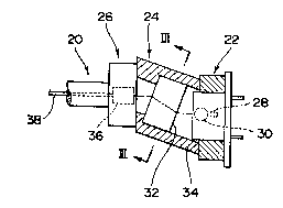
2 8 Reference i9 directed to FIG. 5 for a closer study of the
2 9 optical isolator assembly 24. Cylindrical In shape, the optical isolator 32
3 o is slidably received in the tubular package 34 for angular displacement
3 1 about their common axis. A pair of ribs 40 are formed longitudinally
3 2 and in diametrically opposite positions on the surface of the optical isola-
3 3 tor 32. These ribs 40 are received respectively in a pair of recesses 42
3 4 in the inside surface of the tubular package 34. The recesses 42 are
3 5 each wider than each rib 40, so that the isolator 32 is rotatable relative
3 6 to the package 34 within the limits that are determined by the difference
2(~03090
in width between ribs 40 and recesses 42.
2 At 44 is seen an access opening of rectangular shape
3 formed in the package 34. The isolator 32 may be revolved within the
4 package 34 through this access opening 44.
FIG. 6 is a diagrammatic illustration of an axial section
6 through the optical isolator 32. It has a housing 46 having a beam
7 entrance opening 48 and a beam exit opening 50. Rigidly supported by
8 and within the housing 46 is a permanent magnet 52 of tubular shape.
g A Faraday rotator 54 and a polarization-dependent beam splitter 56 are
disposed about a common optical axis within the permanent magnet 52.
1 1 The beam splitter 56 takes the form of a prism having a beam-splitting
1 2 film 58. Thus the optical isolator 32 can be largely of prior art con-
1 3 struction.
14 Such being the construction of the semiconductor laser
1 5 module 20 for use in the practice of this invention, the method of ad-
1 6 justing the angular position of the optical isolator 32 according to the
1 7 invention will now be described. First, as illustrated in FIG. 7A, the
1 8 optical isolator 32 may be fully turned clockwise, as viewed in this
1 9 flgure, relative to the isolator package 34, until each of the pair of ribs
2 o 40 on the isolator comes into abutment against one of the opposite pack-
2 1 age wall9 bounding each recess 42.
2 2 Then, with the isolator 32 and the package 34 held in the
2 3 relative angular positions of FIG. 7A, the complete isolator assembly 24
2 4 (isolator 32 and package 34) may be turned relative to the semiconductor
2 6 laser assembly 22 in the same direction as the isolator 32 was turned
2 6 relative to the package 34. The rotation of the i901ator assembly 24
2 7 relative to the laser assembly 22 may be discontinued when the IOS9 of
2 8 the forward ~polarized beam starts increasing at the wavelength j~ of
2 9 the beam emitted by the semiconductor laser 28, as indicated by the
3 o solid-line curve in the graph of FIG. 8. Then, in the relative angular
31 positions thus determined, the laser assembly 22 and the isolator assembly
3 2 24 may be locked together against rotation with respect to each other.
3 3 FIG. 7B shows the isolator 32 subsequently turned counter-
3 4 clockwise relative to the package 34 until the pair of ribs 40 thereon .
3 5 butt on the other package walls bounding the recesses 42. With such
3 6 counterclockwise turn of the isolator 32 the ~ and S~polarization curves :
--~: .
8 ~:
200:~05~0
of FIG. 8 will shlft from their solid-line positions toward those indicated
2 by the dashed lines. It is therefore possihle to appropriately determine
3 the characteristic curves in relation to the wavelength of the output
4 beam of the semiconductor laser 28 with a view to unvarying forward
loss and isolation characteristics in the face of possible variations in the
6 laser beam wavelength.
7 The reader's attention is invited to the fact that the
8 allowed stroke of angular displacement of the optical isolator 32 relative
g to its pacl~age 34 should not be made indefinitely long. For, in that
10 case, the ~polarization curve of FIG. 8 would shift too much, with the
11, consequent deterioration of isolation. The stroke should be so determined
12 as to avoid such deterioration.
13 It is, of course, understood that the present invention is
14 not to be limited by the exact details of the foregoing disclosure. A
variety of modifications, alterations or adaptations will readily occur to
16 those versed in fiber optics and allied arts. For example, in order to
17 determine the stroke of relative angular displacement between optical isola-
18 tor and its package, a rib or ribs or similar projections may be formed
19 on the inside surface of the package, and an associated recess or recess-
2 0 es in the housing of the isolator. It is therefore appropriate that the
21 invention be construed broadly and in a manner consistent with the fair
2 2 meaning or proper scope of the following claims.
23
24
26
27
28
29
31
32
33
34
3 5
36