Sélection de la langue

Search

Sommaire du brevet 2003548 

Énoncé de désistement de responsabilité concernant l'information provenant de tiers

Une partie des informations de ce site Web a été fournie par des sources externes. Le gouvernement du Canada n'assume aucune responsabilité concernant la précision, l'actualité ou la fiabilité des informations fournies par les sources externes. Les utilisateurs qui désirent employer cette information devraient consulter directement la source des informations. Le contenu fourni par les sources externes n'est pas assujetti aux exigences sur les langues officielles, la protection des renseignements personnels et l'accessibilité.

Disponibilité de l'Abrégé et des Revendications

L'apparition de différences dans le texte et l'image des Revendications et de l'Abrégé dépend du moment auquel le document est publié. Les textes des Revendications et de l'Abrégé sont affichés :

  • lorsque la demande peut être examinée par le public;
  • lorsque le brevet est émis (délivrance).
(12) Brevet: (11) CA 2003548
(54) Titre français: RAIL A GALETS A MECANISME ELEVATEUR
(54) Titre anglais: ROLLER TRACK ASSEMBLY INCORPORATING A MECHANICAL ELEVATOR MECHANISM
Statut: Périmé et au-delà du délai pour l’annulation
Données bibliographiques
(51) Classification internationale des brevets (CIB):
  • B65G 13/00 (2006.01)
  • B65G 13/12 (2006.01)
(72) Inventeurs :
  • THORNDYKE, ROBERT JOHN (Canada)
(73) Titulaires :
  • ROBERT J. THORNDYKE
(71) Demandeurs :
  • ROBERT J. THORNDYKE (Canada)
(74) Agent:
(74) Co-agent:
(45) Délivré: 1993-04-27
(22) Date de dépôt: 1989-11-21
(41) Mise à la disponibilité du public: 1990-05-22
Requête d'examen: 1990-04-19
Licence disponible: S.O.
Cédé au domaine public: S.O.
(25) Langue des documents déposés: Anglais

Traité de coopération en matière de brevets (PCT): Non

(30) Données de priorité de la demande:
Numéro de la demande Pays / territoire Date
274,961 (Etats-Unis d'Amérique) 1988-11-22

Abrégés

Abrégé anglais


ABSTRACT
An elevating roller track assembly having a base member
and a lift bar located in a channel which is formed in the base
member. The lift bar is slidably mounted for longitudinal
movement relative to the base member. A first elevator ramp is
mounted on the lift bar. The first ramp has a first ramp face
which is inclined upwardly toward a first end of the base member.
A roller support member is slidably mounted in the base for
longitudinal movement. The roller support member has a bottom
wall overlying the lift bar. A plurality of load supporting
rollers are mounted for rotation on and extending upwardly from
the roller support member. A second elevator ramp is mounted on
the bottom wall of the roller support. The second elevator ramp
has a second ramp face which extends parallel to the first ramp
face in a face-to-face relationship therewith. A drive mechanism
is provided for driving the lift bar to and fro with respect to
the base member to cause the first and second ramp faces to slide
over one another to raise or lower the roller support member and
its associated rollers as required in use.

Revendications

Note : Les revendications sont présentées dans la langue officielle dans laquelle elles ont été soumises.


THE EMBODIMENTS OF THE INVENTION IN WHICH AN EXCLUSIVE PROPERTY
OR PRIVILEGE IS CLAIMED ARE DEFINED AS FOLLOWS:
1. A self-contained elevating roller track assembly comprising:
a) a base member having first and second ends, a longitudinally elongated
channel formed in said base member, said channel having a bottom wall, a pair of
oppositely disposed side walls and an open upper end, a passage opening through said
bottom wall,
b) a lift bar located in said channel and slidably mounted on said bottom wall
for longitudinal movement relative to the base member, a mounting bracket attached to the
lift bar and extending through the passage formed in the bottom wall of the base member,
c) first elevator ramp means on said lift bar, said first ramp means having a
first ramp face which is inclined upwardly toward the first end of the base member,
d) a roller support member slidably mounted in said channel for longitudinal
movement therein, said roller support member having a bottom wall overlying said lift bar,
e) a plurality of load supporting rollers mounted for rotation on and extending
upwardly from said roller support member,
f) second elevator ramp means on said bottom wall of said roller support, said
second elevator ramp means having a second ramp face which extends parallel to said first
ramp face in a face-to-face relationship therewith,
g) drive means for driving the lift bar to and fro with respect to the base
member to cause said first and second ramp faces to slide over one another to raise or
lower the roller support member and its associated rollers as required in use said drive
means comprising an extensible ram which has first and second ends, said ram being
extensible to move the second end with respect to the first end, the extensible ram being
located below the base member, the first end of said ram being mounted on said base
member and said second end being mounted on said mounting bracket of said lift bar.

Description

Note : Les descriptions sont présentées dans la langue officielle dans laquelle elles ont été soumises.

2003548
TITLE
ROLLER TRACR ASSEMBLY INCORPORATING
A MECHANICAL_ELEVATOR MECHANISM
Background of Invent on
This invention relates to roller conveyor systems. In
particular, this invention relates to roller conveyors which
incorporates an elevator mechanism for raising and lowering the
rollers.
Field of Invention
Roller systems which incorporate an elevator system are
well known. The elevator system which is commonly used in roller
conveyor systems which are mounted on the bed of a truck employs a
pneumatic elevator device. These devices have been in use for
many years and incorporate an inflatable bladder which when
inflated will serve to raise the rollers to an operating position
and when deflated will serve to lower the rollers. The rollers
are raised and lowered with respect to the floor of a truck or the
like in order to facilitate the movement of cargo along the truck
when they are in the raised position while permitting the load to
rest securely upon the floor of the truck when the rollers are in
the lowered position. The problem with the inflatable system
presently in use is that these mechanisms are subjected to rugged
use in a hostile environment and there is a danger that the
inflatable bladder may be punctured because of the exposure to
this hostile environment.
Summary of Invention
I have found that it is possible to provide a simple,
inexpensive and highly reliable elevator mechanism in a conveyor
': ' " '
~ . .' -: .
.

2~35~8
roller assembly without the need to use an inflatable bladder.
It is an object o~ the present invention to provide a simple and inexpensive
mechanical elevator mechanism in a roller conveyor system.
According to one aspect of the invention there is provided a self-contained
elevating roller track assembly comprising a base member having first and second ends, a
longitudinally elongated channel formed in said base member, said channel having a
bottom wall, a pair of oppositely disposed side walls and an open upper end, a passage
opening through said bottom wall, a lift bar located in said channel and slidably mounted
on said bottom wall for longitudinal movement relative to the base member, a mounting
bracket attached to the lift bar and extending through the passage formed in the bottom
wall of the base member, first elevator ramp means on said li* bar, said first ramp means
having a first ramp face which is inclined upwardly toward the ~1rst end of the base
member, a roller support member slidably mounted in said channel for longitudinal
movement therein, said roller support member having a bottom wall overlying said li* bar,
a plurality of load supporting rollers mounted for rotation on and extending upwardly from
said roller support member, second elevator ramp means on said bottom wall of said roller
support, said second elevator ramp means having a second ramp face which extends
parallel to said first ramp face in a face-to-face relationship therewith, drive means for
driving the li* bar to and fro with respect to the base member to cause said first and
second ramp faces to slide over one another to raise or lower the roller support member
ar d its associated rollers as required in use said drive means comprising an extensible ram
which has first and second ends, said ram being extensible to move the second end with
-- 2 --
~.~ ~ ,...
~1 ~

-` 2~3~
respect to the first end, the extensible ram being located below the base member, the first
end of said ram being mounted on said base member and said second end being mounted
on said mounting bracket of said lift bar.
Brjçf Description of the Drawings
The invention will be more clearly understood after
- 2a -
-.'

- 2003S48
DS46-4643-11
reference to the following detailed specification read in
conjunction with the drawings wherein;
Figure 1 is a pictorial view illustrating a van having
roller conveyors of the type of the present invention mounted in
the floor thereof,
Figure 2 is a pictorial view of a roller conveyor
assembly constructed in accordance with an embodiment of the
present invention,
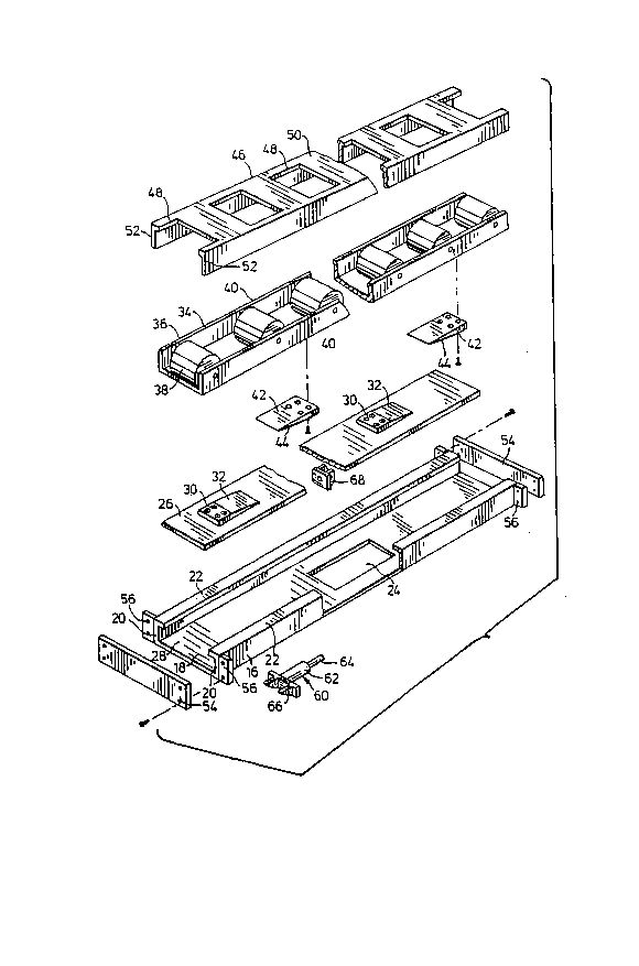
Figure 3 is an exploded view of the assembly of Figure 2,
and
Figure 4 is a partially sectioned side view of a portion
of a roller assembly.
With reference to the drawings, the reference numeral 10
refers generally to a roller assembly constructed in accordance
with an embodiment of the present invention. As indicated in
Figure 1 of the drawings, the roller assemblies 10 may be
positioned on the floor 12 of a van 14 for use in transporting
loads into and out of the van.
As shown in Figure 3 of the drawings, the roller assembly
has a base channel member 16 which has a bottom wall 18, a pair of
oppositely disposed side walls 20 and flanges 22 which project
laterally inwardly from the upper end of the side walls 20. A
passage 24 opens through the bottom wall 18.
A lifting bar 26 is proportioned to fit in the channel 28
so as to rest in a face-to-face sliding relationship on the bottom
wall 18 for longitudinal movement relative to the base member 16.

Z()03S48
DS46-4643-ll
A plurality of first elevator ramps 30 are mounted on the
upper face of the lifting bar 26. The ramps 30 each have a ramp
face 32 which is inclined upwardly toward one end of the lift bar.
A roller support member 34 is provided in the form of a
U-shaped channel member 36 in which rollers 38 are mounted for
rotation so that an arcuate portion of the periphery of each
roller 38 will project above the upper edges 40 to the channel
member 36. A plurality of second elevator ramps 42 are mounted on
the underside of the channel member 36. Each of the ramp members
42 has a second ramp face 44 which extends parallel to the first
ramp face 32 of the first ramp members 30. The roller support
member 34 with the second elevator ramps 42 attached thereto is
mounted in the channel 28 so that the second ramp members 42 rest ~ .
on the lift bar with the ramp faces 44 arranged in a face-to-face
relationship with respect to the ramp faces 32.
A cover 46 is formed with a plurality of apertures 48 in
the upper wall 50. The cover 46 has short side walls 52 which
extend downwardly from the top wall and are arranged to overlie : .
the side walls 20 of the face member 16. The apertures 48 are .
proportioned to permit a segment of each roller 38 to project
upwardly therethrough when the roller support member or cage 34 is
elevated.
- 4

20035~8
DS46-4643-11
Opposite ends of the base member 18 are closed by end
plates 54 which are releaseably attached to the flanges 56 which
project laterally from opposite sides of the base member 16.
The drive mechanism which is used for moving the lift bar
26 comprises an extensible ram assembly 60 which includes a
cylinder 62 and a shaft 64. One end of the cylinder 62 is
connected to a mounting bracket 66 which is attached to the
underside of the bottom wall 18 of the base member 16. The shaft
64 is mounted in a bracket 68 which is attached to the underside
of the lift bar 26.
By extending the ram 60, the shaft 64 will move the
bracket 68 to the right of the position shown in Figure 4 and will
thus cause the lift bar 26 to move to the right. As a result, the
ramp member 30 will move to the right. This will cause the ramp
member 42 to be elevated and this in turn will cause the roller
support member 34 to be elevated. ~y elevating the roller support
member 34, the rollers 38 will be caused to project through the
passages 48 to extend above the top face of the upper wall 50 so
that they may be used for the purposes of providing a roller
conveyor along which items may be conveyed into and out of the
load storage compartment of the truck or the like.
When the roller conveyor system is not required, the
extensible ram 60 is reactivated to return the lift bar to the
original position shown in Figure 4 and the rollers 36 are lowered
to the level of the upper face of the cover 50 so that they are
not functional as a conveyor.
-- 5

~00~3548
DS46-4643-11
From the foregoing, it will be apparent that the present
invention provides a simple and inexpensive form of elevatoring
roller track assembly which does not require an inflatable bladder.
With the exception of the elevator ramp members, the
roller track assem~ly is preferably made from metal such as steel
or the like. The elevator ramp pads are preferably made from a
wear-resistant, low-friction plastics material such as nylon or
Teflar.
''''' ' '
- 6 - .:.
~ ' ~
: . ...:
' -. '

Dessin représentatif
Une figure unique qui représente un dessin illustrant l'invention.
États administratifs

2024-08-01 : Dans le cadre de la transition vers les Brevets de nouvelle génération (BNG), la base de données sur les brevets canadiens (BDBC) contient désormais un Historique d'événement plus détaillé, qui reproduit le Journal des événements de notre nouvelle solution interne.

Veuillez noter que les événements débutant par « Inactive : » se réfèrent à des événements qui ne sont plus utilisés dans notre nouvelle solution interne.

Pour une meilleure compréhension de l'état de la demande ou brevet qui figure sur cette page, la rubrique Mise en garde , et les descriptions de Brevet , Historique d'événement , Taxes périodiques et Historique des paiements devraient être consultées.

Historique d'événement

Description Date
Inactive : CIB de MCD 2006-03-11
Le délai pour l'annulation est expiré 1999-11-22
Inactive : Demande ad hoc documentée 1999-10-01
Lettre envoyée 1998-11-23
Accordé par délivrance 1993-04-27
Demande publiée (accessible au public) 1990-05-22
Toutes les exigences pour l'examen - jugée conforme 1990-04-19
Exigences pour une requête d'examen - jugée conforme 1990-04-19

Historique d'abandonnement

Il n'y a pas d'historique d'abandonnement

Historique des taxes

Type de taxes Anniversaire Échéance Date payée
TM (brevet, 8e anniv.) - générale 1997-11-21 1997-09-19
Titulaires au dossier

Les titulaires actuels et antérieures au dossier sont affichés en ordre alphabétique.

Titulaires actuels au dossier
ROBERT J. THORNDYKE
Titulaires antérieures au dossier
ROBERT JOHN THORNDYKE
Les propriétaires antérieurs qui ne figurent pas dans la liste des « Propriétaires au dossier » apparaîtront dans d'autres documents au dossier.
Documents

Pour visionner les fichiers sélectionnés, entrer le code reCAPTCHA :


Pour visualiser une image, cliquer sur un lien dans la colonne description du document. Pour télécharger l'image (les images), cliquer l'une ou plusieurs cases à cocher dans la première colonne et ensuite cliquer sur le bouton "Télécharger sélection en format PDF (archive Zip)" ou le bouton "Télécharger sélection (en un fichier PDF fusionné)".

Liste des documents de brevet publiés et non publiés sur la BDBC .

Si vous avez des difficultés à accéder au contenu, veuillez communiquer avec le Centre de services à la clientèle au 1-866-997-1936, ou envoyer un courriel au Centre de service à la clientèle de l'OPIC.


Description du
Document 
Date
(aaaa-mm-jj) 
Nombre de pages   Taille de l'image (Ko) 
Abrégé 1994-07-15 1 42
Revendications 1994-07-15 1 51
Dessins 1994-07-15 3 140
Description 1994-07-15 7 297
Dessin représentatif 1999-07-29 1 42
Avis de rappel: Taxes de maintien 1997-09-09 1 119
Avis concernant la taxe de maintien 1998-12-20 1 177
Deuxième avis de rappel: taxes de maintien 1999-05-24 1 119
Avis de rappel: Taxes de maintien 1999-08-23 1 130
Taxes 1997-09-18 2 105
Taxes 1996-11-03 3 89
Correspondance 1996-10-06 1 19
Taxes 1996-09-16 1 65
Taxes 1996-02-26 1 37
Taxes 1996-02-26 2 112
Taxes 1994-11-20 1 53
Taxes 1993-11-21 1 45
Taxes 1992-11-19 1 42
Taxes 1991-11-20 1 43
Correspondance reliée au PCT 1989-11-20 2 30
Correspondance de la poursuite 1992-03-09 2 34
Correspondance reliée au PCT 1996-03-17 1 24
Correspondance reliée au PCT 1996-02-26 1 48
Correspondance reliée au PCT 1993-02-16 1 39
Correspondance de la poursuite 1990-04-18 1 40
Demande de l'examinateur 1991-09-11 1 41
Courtoisie - Lettre du bureau 1996-04-22 1 14
Courtoisie - Lettre du bureau 1996-04-22 1 17
Courtoisie - Lettre du bureau 1995-03-05 2 71
Courtoisie - Lettre du bureau 1990-06-12 1 17
Courtoisie - Lettre du bureau 1990-04-04 1 57