Note : Les descriptions sont présentées dans la langue officielle dans laquelle elles ont été soumises.
;~0()4316
06-12~9822)A
COMPOSITE SOLAR/SAFETY FILM
AND LAMINATED WINDOW ASSEMBLY MADE THEREFROM
BACKGROUND OF THE INVENTION
The present invention relates to encapsulated solar reflecting
5 films for use in laminated window assemblies and more particularly to
shatterproof window assemblies having a safety glass type of con-
struction. It further relates to shatterproof laminated window assem-
blies having high reflection of solar radiation without sacrificing opti-
cal properties and defrosting capabilities. The invention finds partic-
10 ular utility in automotive window applications, and in particular forwlndshield products.
Solar reflecting window assemblies have round application in
numerous areas where one ob~ective is to manage internal heat loads
by reflecting a portion of the solar spectrum which causes heating,
15 e.g., the near infrared. This technology has been employed, for exam-
ple, in commercial and residential glazing products and more recently
in automotive window products.
The surface areas of automotive windows (front, side and rear)
exposed to slmlight have increased in recent years due to the new
20 stylish and aerodynamic vehicle body designs with severely sloping
front and rear windows. This increase has resulted in greater heat
inside of the vehicles during sunny days and greater frosting, icing and
fogging of the windows during the colder days and nights. To reduce
the heating effects resulting from such windows, selective light trans-
25 mitting materials or films have been incorporated into window assem-
blies. These films have generally been designed to maximize rejection
of incoming light in the near infrared wavelength range. Selective
light transmitting films are disclosed, for example, in U.S. Patents
4,166,876, 4,226,910 and 4,234,654. (The disclosures of these patents
Z00431~
- 2 - 06 -12( 9822 ) A
and the other patents and applications mentioned herein are here-
by incorporated by reference in their entireties. ) Electrically-
heatable laminated windows to remedy the frosting, icing and fog-
ging problems have been designed and such are disclosed in, for
example, U.S. Patent Nos. 4,017,661; 4,782,216 and 4,786,783.
Further, it is known to provide a safety glass type of
construction which is resistant to shatter upon impact by making
a laminated window assembly incorporating a flexible plastic
safety film (e.g., polyvinyl butyral, PVB) between a pair of
glass layers. By including a thin electrically-conductive metal
coating in this construction, the safety glass type of windshieJd
can also have electrically-powerable defrosting capabilities as
previously mentioned. This type of coating is disclosed, for
example , in U . S . Patents 3 / 71 8 , 535 , 3,816,201, 3,962,488 and
4,017,661.
Safety glass type windows, which include the metal
layer-containing solar rejection films, reflect heat, control
solar radiation, and optionally conduct electricity for de-
frosting capabilities. Providing such a structure on a com-
mercial scale, however, heretofore has been difficult due to
problems associated with lamination. In a typical construction,
the solar control film is itself of multilayer design with a
number (e.g., three, five, seven or more) of functional coatings
on a flexible plastic substrate or carrier layer. This substrate
layer, typically polyethylene terephthalate (PET), while trans-
parent, tends to wrinkle during bonding to the safety film (e.g.,
PVB) and/or lamination of the resulting composite solar/safety
film between two additional glass layers using conventional
lamination techniques empolyed for safety glass laminates. These
wrinkles, which are particularly noticeable at oblique viewing
angles, render the resulting windshield unacceptable because a
wrinkled layer in the laminate produces optically non-uniform
surfaces which result in distorted reflected images.
One attempt of the prior art to deal with this optical problem
is described in US Patent No. 4,456,736 which uses a solar reflec-
ting coating on a substrate which is heat shrinkable within certain
20l~16
- 3 - 06-12(9822)A
carefully prechosen limits. The major problem with this approach is
the potential for unequal thermal shrinkage of the substrate film and
the coatings, whlch can cause the coatings to become discontinuous.
Discontinuities in the coating can result in degradation of both elec-
trical properties (i.e., higher resistance) and optical properties (i.e.,
an increase in the scattering of visible light).
SUMMARY OF TH~ INVENTION
Accordingly, it is a principal object of the present invention to
provide a composite solar/safety film which, when included in a lami-
nated safety glass window assembly, exhibits good solar rejection
characteristics and acceptably low visible distorted reflection images
from wrinkles in the solar control film.
Another object of this invention is to provide a laminated
safety glass window assembly containing a solar control film, this
assembly exhibiting high reflection of near infrared solar radiation
and acceptably low visible distorted reflection images from wrinkles
in the solar control film.
A further object of the present invention is to provide an
improved safety-glass type electrically-conductive vehicle windshield
containing an optical element capable of high luminous transmittance
of more than seventy percent and low reflected color, particularly at
oblique viewing angles, and reduction of transmitted, near infrared
solar radiation to minimize the heat buildup within the vehicle.
Directed to achieving these objects, an improved laminated
window construction is provided herein. This window includes a solar
control film formed by a flexible plastic substrate such as a PET film
having on one surface a multilayer solar coating. This multilayer
solar coating comprises at least one thin layer of metal and at least
one adjacent adherent layer of a dielectric material. The solar coat-
ing may be deposited on the substrate, for example, by vacuum coat-
ing techniques. An energy absorbing safety film of the type normally
used in shatterproof glass laminates (e.g., PVB) is bonded to at least
one side, and preferably both sides, of the solar control film to form a
composite solar/safety film. This composite solar/safety film is spe-
cially designed to contribute, af ter incorporation into a glass
Z0043~fi
- 4 - 06-12(9822)A
laminate, no more than about two percent of visible reflection (based
on total incident visible radiation) which has the effect of substan-
tially masking the visible effects of wrinkles in the solar control film
substrate (i.e., the wrinkles are made less visible). This low level of
5 visible reflection contribution is achieved by careful control of the
optical properties of the solar control film, the safety film or both.
Outer layer transparent glass panes are laminated to one or both sides
of the composite solar/safety film to provide a safety window which
in one preferred embodiment is a windshield having at least seventy
10 percen~ normal visible light transmissibility, as specified in ANSI
Z26.1 and required in the U.S. automotive industry, and more particu-
larly having a total reflection of visible light of generally less than
ten percent.
Other objects and advantages of the present invention will
15 become more apparent to those persons having ordinary skill in the
art from the foregoing description taken in conjunction with accom-
panying drawings.
BRIEF DESCRIPTION OF THE DRAWINGS
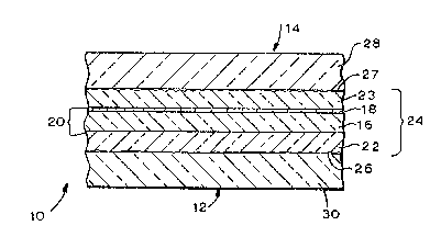
Figure 1 ls a cross-sectional view of one embodiment of a
20 safety glass lamlnate of the present invention.
Figure 2 is a cross-sectional view of another embodiment of a
safety glass laminate of the present invention.
Figure 3 is an enlarged view of a section of the solar control
film portion of the laminate of Figure 1 illustrating a first embodi-
25 ment thereof.
Figure 4 is a view similar to Figure 3 illustrating a secondembodiment of the solar control film portion of the present invention.
Figure 5 is a schematic drawing of one embodiment of an appa-
ratus for forming a composite solar/safety film of the present
30 invention.
Figure 6 is a cross-sectional view of a sample used in the deter-
mination, according to this invention, of the reflectance contribution
of the composite solar/safety film.
Figure 7 is a reflectance spectra for one sample tested in
35 Example 1.
Z00~31fi
- 5 - 06-12(9822)A
Figure ~ is a reflectance spectra for another sample tested in
Example 1.
Figure 9 is a diagram illustrating the arrangement used to
assess the appearance of laminate samples in Example 2.
DETAILED DESCRIPTION OF PREFERRED EMBODIMENTS
OF THE INVENTION
Referring to Figure 1, a solar reflecting safety glass laminate
of the present invention is shown generally at 10. This laminate can
be used in architectural applications, e.g., commercial or residential
glazing, or in vehicle (e.g., automotive) applications, such as wind-
shields, or side and rear windows. In the following description this
laminate will be described primarily in the context of automotive
windshield applications.
The first described element of the laminate of this invention is
substrate layer 16. This substrate layer serves as a carrier for solar
coatings 18 and together substrate 16 and coatings 18 comprise the
solar control film 20. Substrate 16 should be a flexible, transparent
plastic material, that has suitable thermal characteristics to maintain
its integrity and transparency under the conditions employed in subse-
guently described coating, bonding and laminating steps. The
substrate material should also be chosen to provide a refractive index
that is close to that of glass. Known preferred materials of this class
exhibit varying amounts of minute wrinkling under the outlined pro-
cessing conditlons and this invention achieves its primary advantage
in the case of such wrinkle-prone substrate materials.
Among the suitable film forming plastic materials for substrate
16 are biaxially oriented polyesters, such as polyethylene
terephthalate (PET), nylons, polyurethanes, acrylics, polycarbonates,
polyolefins such as polypropylenes, cellulose acetates and triacetates,
vinyl chloride polymers and copolymers and the like. The preferred
substrate material is PET.
The thickness of substrate 16 is not critical and will depend on
the particular application. In general this layer can vary from about
0.5 to 8.0 mils (about 10-200 microns). The preferred substrate for
automotive windshield applications is about 1 to 4 mils (25 to 100
2~:30~31fi
- 6 - 06-12(9822~A
microns). In the most preferred embodiment the substrate is a 2~T
sheet having a thickness of about 2 mil (50 microns).
Substrate 16 may require some form of treatment to render its
surfaces suitable for adhesion to the abutting materials. As indicated
above, one surface of substrate 16 will support solar coatings 18. Typ-
ically, the first of these coating layers, as described below, will be a
dielectric material, e.g., a metal oxide, which generally can be depos-
ited in adherent fashion without any need for substrate priming or
adhesion promoting. The opposing surface of substrate 16 wlll gener-
10 ally be bonded to a safety film, e.g., PVB as described below. In thiscircumstance it is generally necessary to carry out some sort of adhe-
sion promotion treatment on the substrate surface. This treatment
can take a number of forms such as coating the substrate surface with
a thin (e.g., 50 angstroms) non-optical coating of a dielectric mate-
15 rial; coating the substrate surf ace with an adhesive as describedbelow; coating the substrate surface with chemical primers such as
silanes; treating of the substrate surface by flame or by plasma or
electron beam energy in a reactive atmosphere. It is even possible as
described in more detail below to employ an adhesion promoting coat-
20 ing (e.g., dielectric or adhesive) with desirable optical properties suchas an antireflecting layer to aid in achieving the desired refractive
index match.
Solar control film 20 is prepared by applying a multilayer coat-
ing 18 to substrate 16. Coating 18 is optically functional as an inter-
25 ference coating which serves, in a known way, to enhance visibletransmission while reflecting radiation in the near infrared region of
the spectrum. In accordance with the present invention the optical
properties of solar control film 20 are controlled to provide overall
characteristics of the safety glass laminate which mask the promi-
30 nence of wrinkles in the substrate layer which detract f rom theappearance of the laminate.
In general, the contribution which the solar control film
according to the present invention makes to visible reflectance of the
complete laminate should be about 2% or less (based on total incident
35 visible radiation). The contribution to reflection of visible light
~:00431~i
- 7 - 06-12(9822)A
produced by the solar control film 24 in the preferred embodiment is
one percent or less, and most preferably is less than 0.7 pereent. The
visible llght reflection contribution of the remainder of the laminate
will be around eight percent giving a total visible light reflection of
5 ten percent or less. Prior automotive windshields have visible light
reflection contributions for their solar films of three percent or
greater, for a total which is usually more than eleven pércent and can
be as high as seventeen percent. The reflectance contribution values
specified herein refer to observations from one or both sides of the
10 laminate of this invention.
The primary method of achieving low visible reflectance con-
tribution of the solar film in the laminate is by providing a
specially-designed solar coating. It is also possible, as described
below, to aid in achieving this objective by employing absorbing mate-
15 rials between the solar coating layers and the observer.
The solar coating 18 will now be descri~ed with reference toFigures 3 and 4. The solar coating in its most basic form will contain
at least one thin electrically conductive, near infrared reflecting
metal layer and at least one adjacent adherent layer of a dielectric
20 material, these layers which when operatively positioned in the coat-
ing contribute the required low visible reflection. For automotive
windshield applications the metal layer(s) may also be chosen to pro-
vide for defrosting by electrical resistance heating.
The preferred basic coating unit is a three-layer coating of the
25 type shown in Figure 3. In this embodiment coating 18 comprises
dielectric layers 34 and 36 on either side of rnetal layer 38. This basic
stack of three layers can be doubled to give a five-layer design of the
type shown in Figure 4 where layers 40, 42, and 44 are dielectrics and
46 and 48 are metal layers. This is a 2X multiple of the thre~layer
30 because layer 42 while a single material is really two layers - the top
of one three-layer stack and the bottom of another. This arrange-
ment employing two or more spaced metal layers results in an inter-
ference filter of the Fabry-Perout type. Similarly, a seven-layer
stack can be formed using three of the basic stack modules. The
35 higher multiple stacks (e.g., five-layer, seven-layer, nine-layer, etc.)
~:~0~31fi
- 8 - 06-12(g822)A
generally are more desirable since they provide higher total solar
rejection while maintaining acceptable low visible reîlection. See
International Application PCT/US87/0202~.
In general the optical design of interference coatings is known.
5 Among the suitable metals for the metal layerts) are silver, palladium,
aluminum, chromium, nickel, copper, gold and alloys thereof as well
as other alloys such as brass and stainless steel. For optical purposes
the preferred metal is silver.
Metal layer 38 (Figure 3) and metal layers 46 and 48 (Figure 4)
10 should ~e continuous and thereby highly conductive to maximize both
defrosting characteristics and near infrared solar reflection. The
metal layer(s) should be relatively thin to reduce reflected color
which can be particularly undesirable at oblique viewing angles.
When used with known dielectrics of high refractive index as herein-
after described, the thickness of metal layers 38, 46 and 48 should
generally be in the range of about 60 to 120 angstroms with layers of
less than 110 and preferably less than 100 angstroms preferred for
most applications. Preferred thickness for this layer in automotive
applications is about 80 to 120 angstrom with about 90 angstroms
being most preferred. This use of relatively thin metal layers, of
course, results in a concomitant decrease in solar reflection.
Solar coating 18 also contains one or more dielectric layers
shown in Figures 3 and 4 as 34, 36, 40, 42, and 44. These layers,
conventionally employed in solar control films, should be essentially
transparent over the solar range (i.e., from 325 to 2125 nm).
In general the dielectric material should be chosen with a
refractive index which is greater than the material outside the coat-
ing it abuts. For example, dielectric layer 36 of Figure 3 abuts the
substrate 16, typically PET which has a refractive index of about 1.64.
Similarly, dielectric layer 34 will abut a layer of safety film 23, typi-
cally PVB which has a refractive index ,of about 1.5. In general a
higher refractive index of the dielectric layers is desirable. It is pre-
ferred to employ dielectric materials with a refractive index of
greater than about 1.8, and most preferred are dielectrics with
refractive indices above about 2Ø Dielectric layers upon which a
20043~fi
- 9 - 06-12(9822)A
metal layer will be deposited, e.g., layers 36 of Figure 3 and layers 44
and 42 of Figure 4, should also be chosen to provide a suitable surface
for this coating operation. Suitable dielectric materials for layers 34,
36, 40 and 44 include ZrO2, Ta2Os, WO3, In2O3, SnO2, In/SnOx,
5 A12O3, ZnS, ZnO and TiO2. In the embodiment of Figure 4, the
refractive index of layer 42, which serves as a spacer layer for metal
layers 46 and 48, is not as critical as that for layers 40 and 44.
Accordingly, dielectric materials in addition to those listed above can
be used for this spacer layer, e.g., SiO, SiO2 and MgF~. In general the
10 refractive index need only be above about 1.5 for this spacer layer.
The preferred dielectric materials for automotive applications are
WO3, In2O3 and Sn2-
The thickness of the dielectric layers is chosen, in known fæh-
ion, to obtain an optical thickness which provides maximum reflec-
tion suppression in the 500-600 nm wavelength region. Depending on
the particular dielectric chosen this will generally require dielectric
layers of from about 200-600 angstroms. A typical preferred three-
layer construction of the type shown in Figure 3 can comprise:
layer 34 - WO3 - 400 angstroms
layer 38 - Ag - 90 angstroms
layer 36 - WO3 - 400 angstroms
The same basic design criteria apply to the five-layer coatings
shown in Figure 4. Spacer layer 42 between the two metal layers gen-
erally can be about twice the thickness of other dielectric layers (e.g.,
400-1200 angstroms). A typical preferred five-layer construction of
the type shown in Figure 4 can comprise:
layer 40 - WO3 - 400 angstroms
layer 46 - Ag - 90 angstroms
layer 42 - WO3 - 800 angstroms
layer 48 - Ag - 90 angstroms
layer 44 - WO3 - 400 angstroms
Individual layers of the solar coating are deposited by vacuum
coating techniques well known in the art such as vacuum evaporation
or sputtering. Usable methods include evaporation (resistance heated,
ZU043~6
- 10- 06-12(9822)A
laser heated, or electron-beam vaporization) and DC or RF sputtering
(diode or magnetron) under normal or reactive conditions.
After preparation of solar control film 20, this ~ilm is bonded to
at least one layer of safety film of the type normally used in safety
5 glass or shatterproof laminated windows to form a composite solar/
safety film 24 (Figure 1). The known function of this safety film is to
absorb energy of impact on the laminate and prevent glass from flying
off the laminate after it is broken.
The functional requirements of this safety film include (1) good
10 adhesiveness to glass, (2) good modulus of elasticity, (3) good refractive
index match for gla~s (i.e., near 1.5), (4) good optical clarity, and (5)
good optical stability over the useful life of the window.
Among the suitable flexible transparent plastic film-forming
materials for this safety film are plasticized polyvinyl butyral (PVB),
15 polyurethanes, polyvinyl chloride, polyvinyl acetal, polyethylene, ethyl-
ene vinyl acetates and the like. The preferred safety film is a
plasticized PVB sold by Monsanto Company as SAFLEX~, TG sheet. See
U.S. Patent 4,654,179.
The preferred composite solar/safety film 24 is shown in Figure
20 1 as a sandwich of the solar control film 20 encapsulated between two
safety film sheets 22 and 23. In an alternative embodiment shown in
Figure 2, composite solar/safety film 24 comprises solar film 20 and
bonded to one surface thereof, single safety film 23. In this embodi-
ment substrate 16 of solar control film 20 is bonded directly to glass
25 layer 30 with, for example, a suitable transparent adhesive. In the
preferred embodiment where the substrate is PET, adhesives which can
be employed include polyester adhesives (e.g., Nos. 46950, 46960, 46971
and 46690 in DuPont Technical Bulletin No. 17 -- "Polyester Adhe-
sives~), polyamide resin adhesives such as "Versalon" 1140 ~General
30 Mills), and a wide variety of vinyl resin-based adhesives used in the
safety glass-type construction industry. In other embodiments, it is
possible to laminate a composite solar/safety film of the type shown in
Figure 2 dire~tly to a single piece of glass or to a conventional safety
glass laminate (e.g~, a glass/PVB/glass laminate) In these last two
35 embodiments it may be necessary to include on the back side of the
~;:004316
- 11- 06-12(9822)A
solar film substrate (i.e., side opposite the solar coating) an
antireflecting coating layer(s). In any of the embodiments described
herein the use of antireflecting coatings on the substrate backside can
be employed to further lower the reflectance contribution of the solar
films. The interface between PET and PVB for example produces a
reflectance contribution increase of about 0.3%, due to refractive
index mismatch. PET interfaces with other materials, e.g. air, will
result in different values. In a known manner the thickness of the
antireflective layer can be specified based on its refractive index in
accordance with the following equation (for the PET/PVB interface):
n= npET * nPVB
Using this equation results in a refractive index of 1.55. Using a
material with a refractive index of 1.55 in order to obtain a quarter
wavelength antireflection filter at 550 nm, the antireflection layer
would need to be approximately 887 angstroms thick,
Safety films 22 and 23 preferably are provided as manufactured
with one rough surface 26 or 2? and the opposite surface being rela-
tively smooth. See U.S. Patent 4,654,179, columns 5 and 6. The
resulting rough outer surface of the composite solar/safety film per-
mits optimum lamination to glass lagers 28 and 30 by providing escape
pathways for air entrapped between the layers during the conventional
lamination process described below.
In the embodiment shown in Figure 1 it is not necessary for
safety film layers 22 and 23 to be of the same thickness, or even the
same material. The thickness of each safety film layer can vary with
design requirements but generally should be about 5 to 60 mils
(125-1500 microns). In the preferred embodiment of Figure 1 the total
thickness of layers 22 and 23 should be about 30 mils, with the most
preferred configuration cor~sisting of equal 15 mil layers.
In one embodiment of the present invention the contribution to
visible reflection of the solar control film after incorporation into the
final laminate is kept below about 2.0% by including an absorbing ele-
ment between the observer and the solar film. One way to accomplish
this objective is to include a dye or pigment in the safety film, on one
side or both or in one or both of the glass layers. This approach may
~0431~
- 12- 06-12(9822)A
not be preferred in automotive windshield applications where it is nec-
essary to keep visible transmission of ~he laminate above about 70%.
Another absorption approach can involve the use of vapor deposited
absorption coatings, e.g., thin layers of certain metals such as tungsten,
5 nickel or chromium. The visible light absorbing coating can alterna-
tively be deposited on the substrate layer or the solar control coating.
Formation oi the preferred composite solar/safety film will now
be described in connection with Figure 5. In general, the solar film 20
(e.g., fiv~layer coated PET) is encapsulated, i.e., lightly bonded,
between two layers of safety film 22 and 23 (e.g., PVB, each 15 mils
thick) in a nip roll bonding process. Solar film 20 is supplied from roll
50 and first passes over tension roll 51. This solar film then can be
subjected to moderate surface heating at stations 52. ~eating stations
52 can be positioned to heat either the solar film, the PVB sheets or
both. Heating should be to a temperature sufficient to promote tempo-
rary fusion bonding, i.e., the surfaces the PVB become tacky. Suitable
temperatures for the preferred materials are in the range of 48.9 to
121.1C, with preferred surface temperatures reaching about 65.6.
Solar film 20 next is fed along wlth PVB layers 22 and 23 to nip
rolls 53a, 53b (which are rotating in opposite directions) where the
three layers are merged together under moderate pressure to form a
weakly bonded composite solar/safety film. The PVB sheets are sup-
plied by rolls 54a, 54b and the supply line can include tension rolls such
as shown at 55. If desired, nip rol~s 53a, 53b also can be heated to pro-
mote the bonding process. The bonding pressure exerted by the nip
rolls can vary with the film materials and temperature employed but
generally will range from about .7-5.3 kg./sq. cm., and preferably about
1.8-2.1 kg./sq. cm.
The tension of the composite solar/safety film is controlled by
passage over idler roll 56. Typical line speeds through the roll assembly
are in the range of five to thirty feet per minute. Proper control of
speed and tension helps to minimize wrinkling of the PET substrate of
the solar film.
After bonding between nip rolls the weakly bonded composite
3s film is passed over a series of cooling rolls 57a, 57b, 57c, 57d which
Z0~)43~6
- 13- 06-12(9822)A
insure that the product taken up on roll 58 is not tacky. Process water
cooling is generally sufficient to achieve this objective. Tension in the
system is further maintained by idler rolls 59a and 59b.
The resulting composite solar/safety film has a bond strength of
5 about .4-.9 kg. per linear cm. when tested according to the standard
180 peel test. This is sufficient strength to avoid delamination during
normal handling of the composite film. This composite film typically is
sold to laminators who complete the window assembly process as
described below.
Despite the exercise of great care in effecting this bonding pro-
cess, it is not presently possible to produce a composite solar/safety
film 24 that does not exhibit wrinkling to the extent that the optical
properties of the final windshield assembly are adversely affected.
Thus, according to this invention the relationship between substrate
wrinkling and visible light reflection contribution from the solar film is
recognized. More specifically, the adverse optical effects of these
wrinkles are masked by controlling to two percent or less the visible
light reflection contribution of the solar film to the overall laminate.
In this manner, the wrinkles are not eliminated but rendered less visible
to the human eye since the reflection contribution of substrate layer 16
containing the wrinkles is purposely controlled below a predetermined
visibility threshold.
The final component of the laminated window assembly of this
invention is the outer layer(s) of rifid transparent material shown in
Figure 1 at 28 and 30. Layers 28 and 30 preferably are made of glass
but rigid transparent plastics such as polycarbonates, acrylics and the
like may also be employed.
The final step in the process for making the solar reflection
safety laminate of the present invention is the lamination step in
which the composite solar/safety film is laminated to at least one rigid
transparent member. In the preferred product shown in Figure 1 the
laminate consists of a sandwich of the composite solar/safety film
between two 1ass layers.
The composite solar/safety film of the present invention has the
advantage that it can be used in the same manner and laminated
~004316
- 14- 06-12(~822)A
employing the same equipment as that employed in forming conven-
tional safety glass laminates, e.g., containing a single layer PVB safety
fllm. The typical commercial safety glass lamination process com-
prises (1) laying up the three layer assembly, (2) passing the assernbly
S through a pair of nip rolls at room temperature to expel trapped air, (3)
heating the assembly, typically to about 100C, for a short period, e.g.,
about 20 minutes, (4) passing the hot assembly through a second pair of
nip rolls to give the assembly enough temporary adhesion to handle and
(5) autoclaving the assembly typically at 126.7~ to 148.9C and 11.2 to
13.4 kg./sq. cm. for about 10 to 30 minutes. Using present known
commercial lamination techniques it is not possible to press out or
otherwise eliminate the solar film substrate wrinkles which adversely
affect the product quality.
The present invention thus involves the application of the dis-
15 covery that the ability of an observer to see wrinkles in the substratelayer 16 can be significantly reduced by limiting the contribution to the
total laminate reflection made by the solar control film 20 ~Figures 1
and 2) to a prescribed low value. In the preferred embodiment, the
reflectivity contribution of the solar coated film to the total laminate
20 reflectance îs reduced by controlling the nature of the solar coating 18
on the substrate 16. For example, visible reflectance contribution of
the solar control film is reduced by using thinner metal layers and by
using dielectric materials with higher refractive indices and by judi-
cious selection of dielectric thicknesses to insure that reflection sup-
25 pression occurs at appropriate wavelengths in the visible region. Theobserved contribution of the solar control film can also be lowered to
the desired level by placing an absorbing material between the observer
and the solar control film.
In general, the prior art teachings point away from low film
30 visible reflectance because it results in reduced solar reflection (and
consequently higher heat loads) and lower conductance in the resulting
windshield assembly 10. The prior art teaches that the reflection in
the visible range should be high to maximize solar reflection. Lower
reflection of the encapsulated solar control film 20 is also contraindi-
35 cated for defrosting applications since it often involves using thinner
20V'l~
- 15- 06-12(9822)A
metal layers in coating 18, resulting in decreas~d conductance and,
therefore, less defrosting capability for a given applied voltage.
A method as explained below has been developed according to
this invention for determining the contribution to total laminate
s reflection which is made by a composite solar/safety film 24 (Figure 1);
this is an indication of the visibility of the solar control film 20 and
therefore is an indication of how apparent wrinkles in the film
substrate 16 will be.
The determination of contribution to total laminate (i.e., the
multi-layered structure 10 of Figure 1 which includes rigid layers 28,
30) reflection by the solar film (i.e., Rc) requires that one surface of
the sampie laminate be painted black as shown in Figure 6. The sample
laminate, similar to the laminated window 10 of Figure 1, includes solar
control film 20 which is encapsulated between safety film sheets 22, 23
15 and which in turn is laminated between the rigid transparent members
28, 30. The outside surface of sheet 30 is covered with black paint 6D.
In the preferred construction, solar reflecting film 20 is formed of PET
with a sputtered solar coating, the safety film sheets 22, 23 comprise
PVB, and the rigid transparent members are panes of glass. The incom-
20 ing and reflected light rays are shown in the drawing by the arrows,and the terms associated therewith are defined as follows:
Rg = reflection of front glass surface:
Rc = contribution to the total laminate reflection which is made by
the composite solar/safety film.
25 Rt = total measured reflectance for sample in Figure 6.
From Figure 4 it is evident that the total reflectance of that
sample is given by:
Rt = Rg + Rc (eq. 1)
In this equation it has been assumed all glass/PVB layers are refractive
30 indexed matched so that those interfaces do not contribute to measured
reflectance. Note that both sides of the solar film may contribute to
measured reflectance.
Rt can be determined by directly measuring the reflectance of
the sample shown in Figure 6, and Rg can be determined by measuring
35 the reflectance of a plate of glass with the back thereof painted black.
20()~3~i
- 16- 06-12(~822)A
From equation (1), it is obvious that the film~s reflection contri-
bution can be expressed as:
Rc = Rt - Rg (eq. 2)
The equations given above refer to reflectances at a given
5 wavelength. In any given e~uation, it is assumed that all parameters
were determined for the same wavelength. Thus, for example, using
equation (2), the reflectance contribution of the composite solar/safety
film 20 at a certain wavelength can be determined. The calculation
can be repeated at various wavelengths between 380 and 780 nm to
10 obtain a visible reflection spectra for the film. That spectrum can
then be weighted and integrated as described in ASTM standard method
E308, to obtain a luminous reflectance (i.e., Y) based on the 1931 stand-
ard observer and either the A or C standard illuminants. (See also
~Principles of Color Technology~ by F.W. Billmeyer and M. Saltzman,
Wiley ~c Sons, (1981) pages 34-45). The A illuminant, corresponding to
an incandescent light, is used for quantifying the transmission of auto-
mobile windshields because that is the type illuminant used for night
driving. The C illuminant, corresponding to overcast natural daylight,
is used for describing rei'lection because that is the most likely illumi-0 nant under which the appearance of a windshield will be examined.
EXAMPLE 1
Samples were prepared as shown in Figure 6 using as safety film
layers 22 and 23, 15 mil sheets of SAFLEX~ TG (i.e., plasticized PVB);
as solar control film layer 20, a PET substrate with sputtered solar
25 coatings as generally described above in connection with Figures 3 and
4; and as rigid transparent members 28 and 30, 2.2 mm thick plates of
clear glass. The backs of the samples were painted with KRYLON
Ultra Flat Black paint. Transmission and reflectance spectra were
measured on a Perkin Elmer 330 spectrophotometer equipped with a
30 Hitachi 60 mm integrating sphere. For each sample laminate contain-
ing a composite solar/safety film, two reflection spectra were mea-
sured, one before and one after painting one surface black. Using the
procedures outlined above, the reflectance contribution spectrum for
each solar film was determined.
Z0043~6
- 17- 06-12(9822)A
In Figures 7 and 8, the reflectance contribution spectra of solar
films are overlaid with the total reflectance spectra of the correspond-
ing laminated samples (before being painted). Figure 7 shows the
reflectance spectra for sample Ho-107 where the solid line shows the
s total reflectance of the unpainted laminate, and the dotted line shows
film reflectance contribution (i.e., Rc). Figure 8 is a reflectance spec-
tra for sample Ho-81 where the solid line shows the total reflectance of
the unpainted laminate, and the dotted line shows the film reflectance
contribution (i.~e., Rc).
Using the methods described above, reflectance for laminated
samples and for the solar film contribution to the laminate were deter-
mined, and are set forth below in Table 1. It should be noted again,
that the luminous reflectance contribution (i.e., RclumC) determined
for a solar control film 20 encapsulated within a laminated window
15 which includes two outer panes of glass provides an approximate indi-
cation of how easy it is to see that film and therefore the wrinkles in
the substrate.
TA3LE 1
5ample %Rt(LumC) %Rc(LumC)
Ho-107 8.2 O.g
Ho-102 7.5 0.6
Ho-41 8.1 0.7
Ho-39 9.3 2.7
Ho-84 10.1 3.0
Ho-85 13.3 6.3
Ho-76 13.4 6.5
Ho-101 14.3 7.1
Ho-81 15.8 9.1
Ho-80 19.7 13.4
Of the samples considered above, wrinkles in the substrate of
the solar control film were quite difficult to see only in samples
Ho-107, Ho-102, and Ho-~l. These three samples had a solar control
film reflection contribution of less than approximately 1%, low
enough to successfully mask film wrinkles.
200~3~6
- 18- 06-12(9822)A
EXAMPLE 2
This example further demonstrates the use as described herein
of low reflectance films to mask the visibility of wrinkles in PVB-
encapsulated, PET-based, sputter-coated films. More particularly,
this example demonstrates how high the eilm reflectance contribu-
tion can be before wrinkles in an encapsulated film become so evi-
dent as to be unacceptable in a commercial product.
lt is noted that in the cases considered below, the PET wrin-
kles were never totally masked. However, the difficulty in detecting
the presence of wrinkles varies drastically. To totally mask PET
wrinkles would require that reflectance at the PET/PVB interface be
approximately zero. However, even when clear PET is encapsulated,
one can still see wrinkles with some effort. This is because the mis-
match in refractive indices between PVB and PET (i.e., 1.47 vs. 1.64)
leads to a modest reflection (approximately 0.3%) at that interface.
Thus, for a single sheet of encapsulated clear PET there are two PVB/
PET interfaces resulting in a total reflection of approximately 0.6%.
To determine the maximum acceptable film reflectance, films
of various reflectivity were prepared and encapsulated within lami-
nates using procedures described below which simulate full scale pro-
cedures and result in laminates exhibiting similar wrinkle problems.
The optical properties of resulting laminates were evaluated visually
and spectroscopically. It was found that when the film reflectance
contribution exceeded 2%, preferably approximately 1%, wrinkles in
the PET film were sufficiently eviden~ to render the laminate
unacceptable.
Encapsulation and Lamination Procedures
(1) Two SAFLEX~ TG sheets (relatively smooth on one side and
textured on the opposite side) were cut to size and placed
(separately) between two panels of .3 cm. Teflon, and then
heated in an oven at 100 degrees Centigrade for fifteen
minutes.
(2) While the PVB was still hot, a sputter coated PET solar control
film (at room temperature) was placed between the smooth
sides of two PVB sheets. All polymer layers were oriented so
200431.fi
- 19- 06-12(g822)A
~ to have their machine directions aligned. While the Teflon
and PVB were still hot, the prelaminate assembly ~including
the Teflon sheets) was passed through a Chemsultants lnterna-
tional nip roller which exerted a sufficient pressure to tack
the three polymer layers together.
(3) The nip rolled sample was allowed to cool to room tempera-
ture, for generally more than fifteen minutes.
(4) The composite solar/safety film was then put between two 2.2
mm thick plates of glass. This assembly was inserted between
two panels of .3 cm. corrugated cardboard and placed within a
Carver heated press.
(5) The press platens were positioned so as to contact the outer
cardboard panels and the sample was heated for fifteen min-
utes at 150 degrees Centigrade.
15 (6) While the temperature was held at 150 degrees Centigrade, the
assembly was placed under 2.8 kg./sq. cm. (i.e., 72 kg. for a
5 x 5 cm. sample) for five minutes.
(7) While retaining the 2.8 kg./sq. cm. pressure, the platens were
cooled with cold water for ten minutes, and the sample was
later removed from the press.
The PET used was Hostaphan #4400-400 from Hoechst
Celanese (four mil thick). Sputtering was done on the bare side
rather than on the side with a slip coating. A Leybold Heraeus Z400
sputter coater was used to prepare the 5 x 5 cm. sputtered films. The
general structure of the sputtered coatings was WO3/Ag/WO3.
Samples with varying visible reflectance were prepared by varying
the thickness of the silver layer. All other deposition parameters
were held constant for the various samples. A detailed description of
the deposition procedure follows:
30 (1) WO?, (400 An~stroms) Prepared by reactively sputtering (dc
magnetron) irom a tungsten target (~5 mm in diameter or 44
sq. cm. in area). Argon was fed into the chamber at 30 sccm
and oxygen at 6 sccm to attain a pressure of ca. 3.5 X 10 3
mbar. The power supplied to the target was 60 watts or 1.4
3s watts per sq. cm. The deposition time was 53 seconds.
200~31~
- 20 - 06-12(9822)A
(2) AQ (variable thicknesses) Prepared by dc magnetron sputtering
from a silver target (75 mm in diameter or 44 sq cm in area).
Argon was fed into the chamber at 30 sccm to attain a pres-
sure of ca. 2.5 X 10 3 mbar. The power supplied to the target
was 28 watts or 0.6 watts per sq. cm. The deposition rate was
about ten angstroms per second.
(3) WO~ (400 An~stroms) The first S0 angstroms of this layer
were reactively deposited on the Ag under mild conditions
(i.e., low wattage and low oxygen) so as not to damage (i.e.,
oxidize) the silver layer. The layer was applied by reactively
sputtering (dc magnetron) from a tungsten target (~5 mm in
diameter or 44 sq. cm. in area). Argon was fed into the cham-
ber at 30 sccm and oxygen at only 1 sccm to attain a pressure
of ca. 3 X 10 3 mbar. The power supplied to the target was
limited to 18 watts or 0.~ watts per sq. cm. The deposition
time was sixty seconds. The remaining 340 angstroms were
deposited by reactively sputtering (dc magnetron) from a tung-
sten target (75 mm in diameter or 44 sq. cm. in area). Argon
was red into the chamber at 30 sccm and oxygen at 6 sccm to
attain a pressure of ca. 3.5 x 10 3 mbar. The power supplied
to the target was 60 watts or 1.4 watts per sq. cm. The depo-
sition time was about forty-five seconds.
The optical properties were analyzed using the methods
described previously. The spectroscopically determined parameters
are given below in Table 2.
TABLE 2
SamPleDescription%Rt(LumC)%Rc(LumC)
---- Clear PET 8.8 0.58
IO290 A silver 9.1 1.22
IO3100 A silver 10.3 2.33
IOl110 A silver 11.7 4.15
IO4120 A silver 12.1 4.47
H92220 A silver 33.5 27.28
.
;~0043~6
- 21 - 06-12t9822)A
The procedure used to evaluate the appearance of the lami-
nated samples is shown in Figure 9. Referring thereto, it is seen that
the laminate sample 70 having a dark background is positioned
between a fluorescent light 72, which is behind shielding 74, and the
observer 76 so that the angle 78 of incidence and reflection is gener-
ally thirty-four degrees, the distance in the "y" direction of Figure 9
between light 72 and sample 70 is forty centimeters, the distance in
the ~Ix~l direction between light 72 and sample 70 is sixty centimeters,
and the distance in the ~x~ direction between sample 70 and observer
76 is one hundred centimeters.
Sample 102 and the clear PET sample were the preferred ones,
and wrinkles in the PET film were quite prominent in the other sam-
ples. Thus the maximum acceptable limit for the film reflectance
contribution is approximately 2% and an upper limit of only 1% is
preferred.
EXAMPLE 3
To demonstrate the use of a pigmented (tinted) interlayer to
reduce reflection from an encapsulated solar film, sample 147 was
prepared. The construction of the final laminate of this sample was:
glass #1 (2.2mm) / 15 mil cl~ar SAFLEX / solar coating / 4 mil PET /
pigmented 15 mil SAFLEX / glass #2 (2.2mm).
The pigmented interlayer thereof was commercially available
as Mass Pigmented SAFLEX Interlayer 365500 (light neutral brown).
This interlayer when placed between two plates of glass gives an
interlayer with a visible transmission of ca. 55%.
The solar coating was prepared as described in Example 2
above for samples 101-I04 with the silver layer thickness being ca. 110
angstroms. The lamination procedure used was identical to that
described in Example 2.
Sample I47 allows one to observe the desirable effect of
reduced visible reflectance. When viewed from the high reflectance
side ~i.e., through glass #1) wrinkles in the film were more evident
than when viewed from the opposite side (i.e., through glass #2). This
is supported by the differences, as set forth below in Table 3, in film
Z00~31fi
- 22 - 06-12(9822)A
reflectivity as observed from opposite sides. These reflectivities
were measured or calculated as described above.
TA~LE 3
Observation Direction LumC %R(Lam~ LumC ~R(Film)
clear side (glass #1) 8.63 2.14
pigmented side (glass #2~ 6.97 0.76
Accordingly, while sacrificing slightly, but not unduly, the
thermal re~ectlon and conductance resistivity properties of the wind-
shield 10, the substrate wrinkles are made effectively transparent by
this invention, thereby remedying the problem without extra manipu-
lation of the PET substrate sheet 16 during the laminate manufactur-
ing process, and in a manner which is commercially practical. Addi-
tionally, the use of the present low reflectance film makes any dust
and other debris introduced into the laminate during the preparation
thereof harder to see.
From the foregoing detailed description, it will be evident that
there are a number of changes, adaptations, and modifications of the
present invention which come within the province of those skilled in
the art. However, it is intended that all such variations not departing
from the spirit of the invention be considered as within the scope
thereof as limited solely by the claims appended hereto.