Note : Les descriptions sont présentées dans la langue officielle dans laquelle elles ont été soumises.
~004608
Description
BUOY WITH REDUCED DRAG
Technical Field
The present invention relates to a buoy, and
more particularly to a buoy with reduced drag.
Backqround of the Invention
Buoys are used on vessels for a variety of
purposes, such as to mark the location of a submerged
object by connecting the buoy to the submerged object
via a line.
In the crabbing industry, a buoy is connected
to one end of a length of line with the other end of
that line connected to a crab pot. The crab pot is
placed in the water and, due to its weight, comes to
rest upon the ocean floor. The buoy floats upon the
ocean surface and allows the subsequent recovery of the
crab pot by providing a convenient marker for the line
connected to the submerged crab pot. Sometimes two
floating buoys are used as markers, with a length of
line interconnecting them.
During recovery of the crab pot, the fishing
vessel motors past the floating buoy and a member of the
crew, using a hand rope with a grappling hook, retrieves
- the line attached to the buoy without the vessel
stopping. The crew member must throw the grappling
30 -hook, hook the buoy line with the grappling hook, pull
the hand rope in, grab the hooked buoy line with his
hands, wrap the buoy line around a winch on the vessel's
deck and then start operating the winch, all while the
vessel is moving and before the slack in the buoy line
is lost and the full weight of the crab pot is borne by
the buoy line. The crab pot, which can weigh as much as
2004608
.~
600 pounds, is then winched to the surface and the crabs
therein recovered.
During manual retrieval of the line attached
to the floating buoy, the buoy is usually pulled upon
the surface of the water producing a drag upon the
retrieved line and requiring a greater exertion by the
crew member prior to placing the line around the winch.
Not only does this wear the crew member out, it slows
him down and lengthens the time required to manually
retrieve the line and wrap it around the winch. As
such, the drag created by the buoy thus increases the
likelihood that the crew member will not be able to
successfully wrap the line around the winch before all
line slack is lost and the crew member finds himself
handling the full weight of the loaded crab pot. In
such a situation, he will be pulled overboard if he does
not let go of the line. Of course, this means the
vessel must turn around and make another pass by the
; buoy so it can be hooked again and successfully
retrieved. Since the drag requires greater exertion by
the crew member to retrieve the line and slows him down,
the vessel must reduce its speed through the water
during retrieval of the line to accommodate the crew
member.
Therefore, there is need in the art for an
improved buoy with reduced drag. The present invention
provides such a buoy, while further providing other
advantages.
Summary of the Invention
An object of the present invention is to
provide a buoy with reduced drag. Another object is to
disturb the surface flow of water around a buoy being
dragged on the surface of the water to produce reduced
drag.
In one embodiment of the present invention, a
plurality of external circumferential ribs are fixed to
200~608
_
the body of a flotational buoy. There is located in the
buoy an opening to allow a line to be attached to the
body of the buoy. The circumferential ribs are placed
upon the buoy such that they are substantially
perpendicular to the direction of travel of the buoy
when the buoy is being dragged upon the surface of the
water.
Brief Description of the Drawings
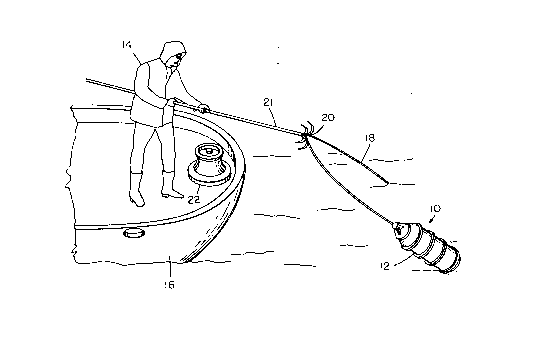
Figure 1 is a perspective view of a crew
member retrieving a line attached to a buoy embodying
the present invention.
Figure 2 is an enlarged side elevational view
r of the buoy shown in Figure 1.
Figure 3 is a fragmentary side elevational
view of an alternate embodiment of a buoy of the present
invention.
Detailed Description of the Invention
A buoy being dragged upon the surface of the
water will produce a pull upon the retrieving line. In
other words, the buoy will produce a drag which must be
overcome by the crew member in order to retrieve the
line attached thereto. Moreover, if the vessel is
moving, this drag will be increased.
The drag associated with a particular buoy
will vary depending upon the size and shape of the buoy.
For example, round buoys utilized in the crabbing
industry may typically produce 24 pounds drag or pull,
whereas an oblong buoy may produce 8 to 12 pounds pull.
As shown in the drawings for purposes of
illustration, the present invention resides in a buoy lo
having a plurality of circumferential ribs 12 upon the
buoy. The ribs are oriented substantially perpendicular
to the longitl~in~l axis of the buoy which corresponds
to the direction of the buoy's travel when pulled. With
the buoy 10 of the present invention, the drag or pull
- Z00~608
of the buoy drops from 8 to 12 pounds to as low as 2 to
3 pounds pull.
The circumferential ribs 12 of the present
invention serve to break the flow of water around the
buoy 10 and thereby create surface turbulence. This
turbulence is believed to result in alleviating the
suction which develops between the buoy and the surface
of the water, and reduces the buoy's drag.
In the crabbing industry, it is advantageous
for a crab boat not to have to slow down or stop each
time a crab pot is retrieved. Therefore, a crew member
14 on a crab boat 16, such as shown in Figure 1, will
retrieve a buoy line 18 attached to the buoy 10 by
throwing a grappling hook 20 attached to the hand rope
21, pull the hooked buoy line in by hand using the hand
rope, and then hurriedly wrap the retrieved buoy line
around a winch 22 before slack in the buoy line is
removed due to the boat's movement. The crew member
would then proceed to winch the crab pot (not shown) to
the surface. Prior to placing the retrieved line 18
around the winch 22, buoy 10 will be dragged upon the
surface of the water making the crew member's task more
strenuous. By providing the buoy with less drag, the
crab boat may maintain a higher speed during the
retrieval process by alleviating a substantial amount of
the drag that would otherwise be produced by the buoy
without the ribs 12 of the present invention.
In other situations it may be necessary to
haul in lines with buoys attached completely by hand.
By decreasing the drag of such buoys, a fisherman faced
with such a task may now decrease the amount of force
required to retrieve such a line. In inclement weather
conditions, a buoy with less drag is particularly
advantageous in that it allows the fisherman to complete
the task of retrieval quickly.
Referring to Figure 2, a preferred embodiment
of the buoy 10 of the present invention is depicted.
~004608
-
Buoy lo has an end 26 which contains an opening 27 to
permit a line 18 (not shown in Figure 2) to be attached
to the buoy. Circumferential ribs 12 fully encircle
buoy 10 and result in the disruption of the flow of
water around the buoy when the buoy is dragged on the
surface of the water.
In order for the ribs 12 to break the suction
created between the buoy 10 and the surface of the
water, it is necessary that the ribs be aligned
lo substantially perpendicular to the direction of the
buoy's travel through the water and project outward
beyond a smooth body portion 28 of the buoy. For
example, longitudinal ribs do not serve to create the
necessary turbulence and, therefore, do not yield a buoy
with decreased drag.
Preferably, the circumferential ribs protrude
from the body an amount sufficient to reduce the buoy's
drag, but do not protrude to an extent whereby the ribs
! cause, rather than alleviate, drag. For example, buoy
10 depicted in Figure 2 may typically be about 62 cm in
length, 30 cm in width, and with ribs 12 protruding from
the smooth body surface 28 approximately 0.3 cm-0.4 cm.
Preferably, the circumferential ribs 12 have relatively
squared edges to provide a sharp edge and thereby
increase the turbulence produced.
While Figure 2 depicts five circumferential
ribs 12 upon the buoy 10, any number of such ribs may be
utilized provided they create the necec.s~ry turbulence
to result in the decreased drag desired. Moreover,
while Figure 2 depicts the circumferential ribs aligned
perpendicularly to the longitudinal axis of the buoy and
its direction of travel upon the water, the ribs need
only be oriented such that the necessary turbulence is
created. Thus, they may be aligned at an angle other
than 90 degrees to the direction of the buoy's travel
upon the water.
20046()8
Referring to Figure 3, an alternative
embodiment of the present invention is depicted. Buoy
10 has arranged upon the smooth body portion 28 a linear
arrangement of spaced rectangular extrusions 13. This
series of protrusions similarly serve to create
turbulence and thereby reduce the buoy's drag upon the
surface of the water.
Although the present invention has been
described in conjunction with preferred embodiments, it
is to be understood that modifications and variations
may be resorted to by those skilled in the art without
departing from the spirit and scope of the invention.
Such modifications and variations are considered to be
within the purview and scope of the invention and the
applied claims.
WD70-lV7