Note : Les descriptions sont présentées dans la langue officielle dans laquelle elles ont été soumises.
~al~r .~ r,
. "
-,' 10
CUFF DEVICE
. . .
The present invention relates to therapeutic and
prophylactic devices, particularly to a cuff device or
; dynamic support that temporarily tightens and loosens
on a wearer's body part as another body part is moved.
Various compressive cuff devices are known such as
the straps that hold braces on a patient's limb and
; 25 trunk to protect ligaments, tendons and bones as they
heal following injury or surgery. Various strapping
devices are also used t~ help prevent injury or provide
support for the chronic instability o~ a body part.
Elastic stockings and inflatable cuffs are used to
reduce edema and blood stasis in the extremities that
result from disease, injury, prolonged confinement or
surgery.
Unfortunately, at the present time, ideal con-
ditions for the efficient application of these braces,
cuffs and stockings cannot be achieved with con-
ventional means. These supporting structures tend to
be either too loose on the body part, in which case the
support members cannot adequately stabilize the body
.~. ....
.~ , . .
,~ .
....
,~ . . .~
*
. " ~ .
~. - .
~005035
40330-702
-2-
stasis or, more frequently, the~e supporting ~tructure~
are held too tightly, intensifying diacomfort, prolonging
immobility and aggravating the problem of ~ta~is or
atrophy.
Accordingly, the present invention provides a
dynamic support for first and second body parts which are
: articulated to each other comprising cuff components
adapted to engage the fir-~t and second body parts when
the fir~t and second body parts are in a resting
position, the cuff component engaging the first and
second body parts at locations spaced from the body area
where the body parts are articulated, arms attached to
and extending from each of the cuff components and
terminating in end regions, said end regions being
movable in attachment to each other at a point adjacent
to the area where the body parts are articulated, a
tightening system attached to the cuff components, said
dynamic support being characterized in that the
tightening system includes members responsive to a
predetermined relative movement between the body parts in
more than one direction away from the resting position
for increasing the tightness with which the cuff
components engage the body parts.
In a second a~pect, the invention is a dynamic
support for first and second body parts which are
articulated to each other comprising cuff components
adapted to engage the first and ~econd body parts when
the first and second body parts are in a resting
po~ition, the cuff components engaging the first and
second body parts at locations spaced from the body area
where the body parts are articulated, arms attached to
and extending from each of the cuff components and
terminating in end regions, ~aid end regions being
movable in attachment to each other at a point adjacent
to the area where the body parts are articulated, a
G~
1~
. ~, .
,~.. ~' , " ' .
:. ,
,
"
200503~
-3-
tightening system attached to the cuff component~, said
dynamic support being characterized in that the
tightening system includes members respoDsive to a
predetermined relative movement between the body parts in
more than one direction for balancing the tightness with
which the cuff components engage the body parts.
In a third aspect, the invention i8 a dynamic
support for first and second body parts which are
articulated to each other, comprising cuff components
adapted to engage the first and second body parts when
the first and second body parts are in a resting
position, the cuff components engaging the first and
second body parts at location~ spaced from the body area
where the body parts are articulated, arms attached to
and extending from each of the cuff components and
terminating in end regions, said end regions being
movable in attachment to each other at a point ad~acent
to the area where the body parts are articulated, a
tightening system attached to the cuff component~ and
including members responsive to a predetermined relative
movement between the body parts in more than one
direction away from the resting position for increasing
the tightness with which the cuff components engage the
body parts, said members re3ponsive to a predetermined
relative movement between the body parts including means
for balancing the tightness with which the cuff
components engage the first and second body parts.
In the drawings:
Fig. 1 is a front elevation view of the dynamic
support in an extended position.
Fig. 2 is a back elevation view of the dynamic
support in an extended position.
Fig. 3 is a side elevation view of the dynamic
support in a flexed position.
Fig. 4 is a side elevation view of the dynamic
support in an extended position.
Y' ~A
,~ .
2005035
Fig. 5 i8 a vertical sectional view taken along line
A-~ of Fig. 4.
Fig. 6 i8 a front elevation view of the dynamic
support of an alternative embodiment of the present
invention.
;-~ Fig. 7 is a side elevation view of the dynamic
support of the alternative embodiment of the present
invention showing the pivot and cable assembly pivoted
from the resting position.
;~ Fig. 8 i8 a vertical sectional view taken along line
B-B of Fig. 7.
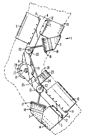
Referring to Figs. 1-5, a cuff device or dynamic
support for the lower extremity and particularly the
knee, is shown, but it is understood that the principles
of the invention are also applicable to other articulated
body parts. There is shown in Fig. 1 a dynamic support 1
which includes an upper or first body part engaging cuff
component 2 and a lower or second body part engaging cuff
component 3. These cuff components comprise a fitting
system and are respectively adapted to engage the body
parts above and
~, . . . .
. .
?,. .
.~. ' .
'.~'
~00~ 35
-5-
A pair of arms 4 and 5 are respectively attached
to and extend toward each other from the body part
engaging cuff components 2 and 3. A set of these arms
are located on opposite sides of the extremity. Each
of these arms 4 and 5 terminate in movable overlapping
end regions 6 and 7 remote from the cuff components and
are formed with aligned openings through which a single
pivot pin 8 extends. A more complex slidable and
pivotable orthotic ~oint can be used. The orthotic
joint can incorporate a rivet limit stop 27 known per
se. The pivotable orthotic joint may also incorporate
a condylar pad 28 known per se secured to the pivot pin
8. End region 7 pivots freely about pivot pin 8.
Thus, pivot pin 8 forms a pivot axis which is generally
perpendicular to the arms 4 and 5 and which coincides
with the predominant axis to which swinging of the
upper and lower body parts are limited. The arms 4 and
5 can be of a slightly flexible material construction
such as metal or plastic. There is an anterior thi~h
upper cross member 9 and posterior calf lower cross
member 10 which can be made of a slightly flexible
formable material such as metal or plastic as are the
arms 4 and 5 and can be shaped to conform to the body
part such as the thigh and leg with heat and shaping
tools. The opposite ends of each of the cross members
9 and 10 are fixed to the ends of each set of the arms
4 and 5 respectively by rivets 11 or the like.
The upper cuff component 2 and the lower cuff
component 3 are constructed of slightly yieldable
material such as plastic or cloth to conform to the
body part configuration. Each of the cu~f components 2
and 3 are attached at one end to one of the arms 4 and
5 respectively by rivets 12 or the like. The cuff
components 2 and 3 pass through sleeves 13 and 14
respectively which are constructed of neoprene material
or the like, pass through a slot 15 located toward the
end of one of the uprights 4 and 5, as shown in Fig. 3,
',
:
" .
., .
200503~
--6--
adjustable and releasable in fixation to themselve~ by a
Velcro (R) strip 18 or the like. The loops 16 and 17 are
attached to a cable 19 which passes through guide 20 and
guide 21 attached to one set of the arms 4 and 5
respectively by a bolt 22 or the like. Straps 23 and 24
are each attached at one end to one of the opposite arm~
5 by rivets 25 or the like and are adjustable and
releasable in fixation to each other by a Velcro
(trademark) strip 26 or the like. Strap~ 23 and 24
resist forward migration on the knee of end regions 6 and
7.
Movement of hinging end regions 6 and 7 cause the
cable 19 to tighten cuff components 2 and 3 on the
extremity by relative shortening of the cable 19 when the
thigh is moved to an extended position relative to the
leg from the flexed position. The segment of the upper
cuff component 2 and lower cuff component 3 that pass
through the sleeves 13 and 14 respectively tighten
generally transverse the long axis of the body part. The
segment of the upper cuff component 2 and the segment of
the lower cuff component 3 that do not pass through the
sleeves 13 or 14 respectively also tighten with a
torsional component in generally opposite directions on
the first and second body parts. Since the upper and
lower cuff components are connected by the cable 19 there
will be a balancing of the amount of tightening of the
upper and lower cuff component~.
Referring to Figs. 6-8, there i~ provided in
accordance with another embodiment of the present
invention, a dynamic support designated generally as 30.
Except as hereinafter described, dynamic support 30 is
substantially identical to the dynamic support 1 and
; operates in the same manner with a tightening system for
dynamically and momentarily tightening the cuff
components on the body parts from the snug close fit
position. Those features of the dynamic support which
are identical to those of the dynamic support of Figs. 1-
5 are identified using the same numbers used in
..i .!.
~ O~J~
each side of the body. Arms 4 and 5 and end regions 6
and 7 and pivot pin 8 operate in the same manner as
those parts shown in Figs. 1-5.
An upper or first body part engaging cuff com-
ponent 31 can be constructed of slightly yieldable
~aterial such as plastic or cloth and consists of a
plurality of straps 32 and 33 which pass, on each end,
through a loop ~4 on each side of the first body part
or trunk. Each strap 32 and 33 is adjustable and
releasable in fixation to itself by a Velcro R strip 36
or the like. A lower or second body part engaging cuff
component 40 constructed of slightly yieldable material
such as plastic or cloth is attached at one end to
lower arm 5 by rivets 41 or the like. The lower cuff
component 40 passes through a sleeve 42, around the
second body part or lower thigh and through a loop 43
and is adjustable and releasable in fixation to itself
by a Velcro R strip 44 or the like. The loops 34 and
43 are attached to a cable 45, which passes through
; guide 46 and guide 47 which is attached by a bolt in a
slot 48 in upper arm 4, guide 49 on end region 7 and
guide SO on lower arm 5. The rate and amount of
tightness of the upper and lower cuff components or
:A 25 dynamic supports can be adjusted by the position of
guide 47 in slot 48.
There is a posteriorly located cross member 51
which can be made of slightly flexible formable
material such as metal or plastic and can be shaped to
conform to the body part, such as the trunk, with heat
and shaping tools. The opposite ends of the cross
member 51 are attached to the ends of each arm 4 by
r~vets 52 or the like.
In use, movement of hinging end regions 6 and 7
cause the cable 44 to tighten cuff components 31 and 32
on the trunk and thigh when the trunk and thigh are
moved in flexion or extension from the resting position
by the relative shortening of cable 45 as end region 7
'
~ .
20~ )35
pivots relative to end region 6 increasing the distance
between guide 47 and guide 48.
Details have been disclosed to illustrate the
invention in a preferred embodiment of which adaptation
and modification within the spirit and scope of the
invention will occur to those skilled in the art. For
instance, the pivot and cable assembly can be incor-
porated into .a dynamic support or cuff device to
tighten and loosen from the close fit resting position
on various body parts such as the trunk and shoulder,
arm and forearm and wrist and hand. The scope of the
invention is limited only by the following claims.