Sélection de la langue

Search

Sommaire du brevet 2005170 

Énoncé de désistement de responsabilité concernant l'information provenant de tiers

Une partie des informations de ce site Web a été fournie par des sources externes. Le gouvernement du Canada n'assume aucune responsabilité concernant la précision, l'actualité ou la fiabilité des informations fournies par les sources externes. Les utilisateurs qui désirent employer cette information devraient consulter directement la source des informations. Le contenu fourni par les sources externes n'est pas assujetti aux exigences sur les langues officielles, la protection des renseignements personnels et l'accessibilité.

Disponibilité de l'Abrégé et des Revendications

L'apparition de différences dans le texte et l'image des Revendications et de l'Abrégé dépend du moment auquel le document est publié. Les textes des Revendications et de l'Abrégé sont affichés :

  • lorsque la demande peut être examinée par le public;
  • lorsque le brevet est émis (délivrance).
(12) Brevet: (11) CA 2005170
(54) Titre français: METHODE DE FORMATION D'UNE CHAINE DE COUPLEURS CROISES POUR FERMETURE-ECLAIR
(54) Titre anglais: METHOD OF FORMING A CHAIN OF MEANDERING COUPLING ELEMENTS FOR SLIDE FASTENERS
Statut: Périmé et au-delà du délai pour l’annulation
Données bibliographiques
(51) Classification internationale des brevets (CIB):
  • A44B 19/18 (2006.01)
  • A44B 19/12 (2006.01)
  • B26D 3/00 (2006.01)
  • B26D 3/30 (2006.01)
  • B29D 5/04 (2006.01)
(72) Inventeurs :
  • FUKUROI, TAKEO (Japon)
(73) Titulaires :
  • YKK CORPORATION
(71) Demandeurs :
  • YKK CORPORATION (Japon)
(74) Agent: GOWLING WLG (CANADA) LLP
(74) Co-agent:
(45) Délivré: 1995-03-28
(22) Date de dépôt: 1989-12-11
(41) Mise à la disponibilité du public: 1990-06-20
Requête d'examen: 1989-12-11
Licence disponible: S.O.
Cédé au domaine public: S.O.
(25) Langue des documents déposés: Anglais

Traité de coopération en matière de brevets (PCT): Non

(30) Données de priorité de la demande:
Numéro de la demande Pays / territoire Date
63-320839 (Japon) 1988-12-20

Abrégés

Abrégé anglais


A method of forming a chain of meandering or zig-zag
coupling elements for slide fasteners comprises dividing or
bifurcating a continuous length of substantially
cross-sectionally circular monofilamentary material axially
into identical halves of substantially semi-circular
cross-section immediately prior to introduction to a forming
apparatus. The identical halves may be provisionally joined
together to provide a cross-sectionally circular
monofilament and divided back into respective halves
immediately prior to formation thereof into respective rows
of coupling elements for slide fasteners.

Revendications

Note : Les revendications sont présentées dans la langue officielle dans laquelle elles ont été soumises.


- 8 -
CLAIMS
1. A method of forming a chain of meandering coupling
elements for slide fasteners which comprises the steps of:
dividing a continuous length of substantially cross-sectionally
circular monofilamentary material along its longitudinal axis into
substantially cross-sectionally semi-circular identical halves;
supplying said monofilament halves to respective die-wheels
having respective peripheral shaping grooves such that respective plane
surfaces of said monofilament halves are disposed upwardly;
passing said monofilament halves transversely across said shaping
grooves and meanderingly around a plurality of shaping pins extending
radially outwardly from said die-wheels and located and distributed on
opposite sides of said shaping grooves in arrangement out of alignment
with one another;
pressing said monofilament halves on said die-wheels by
respectively bending rolls into said shaping grooves to form leg portions
of fastener coupling elements; and
deforming portions of said monofilament halves positioned on the
bottom of said shaping grooves by respective punches to produce
flattened-out coupling head portions of elements.
2. A method according to claim 1 in which said cross-
sectionally circular monofilament comprises cross-sectionally semi-
circular identical halves provisionally jointed together at their respective
planar surface with use of an adhesive.
3. A method according to claim 1 in which said cross-
sectionally circular monofilament comprises cross-sectionally semi-
circular identical halves provisionally jointed together by means of
longitudinal ridges and grooves formed at the planar surfaces
respectively.

Description

Note : Les descriptions sont présentées dans la langue officielle dans laquelle elles ont été soumises.

Z00517Q
BACKGROUND OF THE INVENTION
Field of the Invention:
This invention relates to a method of manufacturing a
chain of coupling elements for slide fasteners and has
particular reference to a method of forming a chain of such
coupling elements from a monofilamentary material having a
semi-circular cross-section into a meandering or zig-zag
structure.
Prior Art:
A prior art of the character described is disclosed
for example in Japanese Patent Publication No. 39-9390 in
which a cross-sectionally semi-circular monofilament is
formed into a continuous meandering coupling element
structure for mounting astride a longitudinal edge of each
of a pair of stringer tapes. Although this prior
publication fails to disclose any specific method of making
such slide fastener coupling elements, it is believed that a
monofilamentary material is spun, formed into an elongated
cross-sectionally semi-circular monofilament and wound on a
bobbin, from which the monofilament is supplied to a
conventional apparatus for forming continuous rows of
coupling elements having a meandering or zig-zag
configuration. However, being semi-circular in cross-
section, the monofilament is apt to become twisted or
otherwise deformed when taken up on the bobbin, and it is
extremely difficult, if not impossible, to correct the
deformed posture of the monofilament so that its cross-

2005~70
sectional shape is reoriented and aligned on processingthrough the forming apparatus, leading to defective coupling
element products.
SUMMARY OF THE INVENTION
It is therefore the primary object of the present
invention to provide a method of forming a chain of
meadering coupling elements for slide fastener from a cross-
sectionally semi-circular monofilament with a great degree
of accuracy and efficiency and without involving the problem
of n twists .
The invention essentially comprises bifurcating or
dividing a continuous length of substantially cross-
sectionally circular monofilamentary material axially into
substantially cross-sectionally semi-circular identical
halves immediately prior to formation thereof into
respective rows of meandering coupling elements for slide
fastener.
According to the invention, there is provided a method
of forming a chain of meandering coupling elements for slidç
fasteners which comprises dividing a continuous length of
substantially cross-sectionally circular monofilamentary
material along its longitudinal axis into substantially
cross-sectionally semi-circular identical halves immediately
prior to formation thereof into respective rows of meander-
ing coupling elements each having leg portions and
flattened-out coupling head portions.
The above object and other features of the invention

2005170
will become more apparent from the following detailed
description taken in conjunction with the accompanying
drawings. Like reference numerals refer to like or
corresponding parts throughout the several views.
BRIEF DESCRIPTION OF THE DRAWINGS
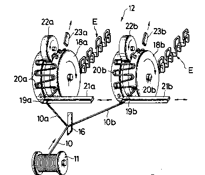
FIG. 1 is a schematic perspective view utilized to
explain the manner in which a monofilament is bifurcated
along its longitudinal axis according to the invention;
FIG. 2 is a perspective view on enlarged scale of one
individual meandering coupling element in a row shcwn in
FIG. l;
FIG. 3 is a schematic perspective view utilized to
explain the manner of biurcating the monofilament which has
been pre-divided and pre-joined according to one embodiment
of the invention;
FIG. 4 is a schematic perspective view utilized to
explain the manner of bifurcating the monofilament which has
been pre-divided and pre-joined according to another
embodiment of the invention;
FIGS. 5, 6 and 7 each are schematic perspective views
of respective means of cutting a cross-sectionally circular
monofilament longitudinally apart into identical halves; and
FIG. 8 is a schematic plan view utilized to explain
the manner in which the monofilament in its bifurcated form
is woven simultaneously with weaving threads into a tape
system.
DETAILED DESCRIPTION

20051~0
Referring now to the drawings and FIG. 1 in
particular, there is shown a monofilament 10 having a
substantially circular cross-section and wound on a bobbin
11. The monofilament 10 is spun from a thermoplastic
resinous material such as polyester, nylon and the like to a
diameter approximately in the range of 0.5 mm to 1.0 mm.
According to the invention, the starting monofilament 10 as
wound on the bobbin 11 is bifurcated or divided axially into
identical halves lOa and lOb each having a semi-circular
cross-section immediately prior to introduction to an
element forming apparatus 12. The cross-sectionally
circular monofilament 10 on the bobbin 11 may be prepared
from two identical monofilaments of semi-circular cross-
section which have been provisionally joined together at
their respective planar surface lOa' and lOb' with use of an
adhesive 13 as shown in FIG. 3, or which have been
provisionally fitted snappingly together by means of
longitudinal ridges 14 and grooves 15 formed at the planar
surfaces lOa' and lOb' respectively as shown in FIG. 4 to
provide a cross-sectionally circular monofilament 10.
The monofilament 10 thus consisting of two
provisionally joined identical halves lOa and lOb is
separated or bifurcated by a wedge-shaped separator 16 which
has a triangular cross-section with its apex 17 serving as a
separating or cutting edge along which the monofilament 10
is separated into cross-sectionally semi-circular halves
immediately in advance to formation on the forming apparatus

2005170
12 as shown in FIG. 1.
Separated monofilament halves lOa and lOb of semi-
circular cross-section are supplied to respective die-wheels
18a and 18b having respective peripheral shaping grooves
l9a and l9b, in which instance the monofilament halves lOa
and lOb are oriented with their respective planar surfaces
lOa' and lOb' held upside up and passed around a plurality
of shaping pins 20a and 20b extending radially outwardly
from the respective die-wheels 18a and 18b. The shaping
pins 20a and 20b are located on opposite sides of the
shaping grooves l9a and l9b and distributed out of alignment
with one another so that the cross-sectionally semi-circular
monofilaments lOa and lOb are moved by respective
reciprocating bars 21a and 21b transversely across the
grooves l9a and l9b to train meanderingly around the shaping
pins 21a and 21b. As the monofilaments lOa and lOb advance
with rotation of the die-wheels 18a and 18b, they are
pressed by respective bending rolls 22a and 22b into the
shaping grooves l9a and l9b so as to form leg portions Ea of
fastener coupling elements E in a continuous formation and
thereafter deformed by respective punches 23a and 23b to
produce flattened-out coupling head portions Eb of the
elements E. The coupling elements E thus formed from the
cross-sectionally semi-circular monofilaments lOa and lOb
into a continuous meandering structure are heat-set and
withdrawn from the apparatus 12. Each individual meandering
element E is shown in FIG. 2.
_ 5 _

Z005170
The starting monofilament 10 having a fully circular
cross-section is separated or bifurcated along its
longitudinal axis into two identical cross-sectionally semi-
circular working monofilaments lOa and lOb by means of the
wedge-shaped separator 16 in a manner shown in FIGS. 3 and
4.
FIG. 5 shows a device for severing a cross-sectionally
circular monofilamentary material M into two identical
cross-sectionally semi-circular halves, which comprises a
guide block 30 having a horizontally extending guide through
aperture 31 through which the material M is fed in the
direction of the arrow and a belt saw 32 rotating in the
block 30 and adapted to cut the material M along a
longitudinal axis thereof into halves lOa and lOb while the
material M is moving.
FIG. 6 shows another severing device comprising a
cutting roll 40 coacting with a press roll 41 for cutting
the material M into two identical cross-sectionally semi-
circular halves lOa and lOb.
FIG. 7 shows still another severing device comprising
coacting upper and lower cutting blades 50 and 51 for
cutting the material M likewise into two identical halves
lOa and lOb.
FIG. 8 shows the monofilament 10 being bifurcated by
the separator 16 and woven into respective longitudinal
edges of a pair of stringer tapes Tl and T2 for a slide
fastener. The bifurcated monofilaments lOa and lOb are

2005170
punched to form the coupling heads Eb at predetermined
intervals as in the case of FIG. 1 and thereafter woven
meanderingly by respective laying-in bars 60 and 61 on a
needle loom into the system of the tapes Tl and T2
simultaneously as the latter are woven in a manner well
known in the art.
Obviously, various modifications and variations of the
present invention are possible in the light of the above
teaching. It is therefore to be understood that within the
scope of the appended claims the invention may be practiced
otherwise than as specifically described.

Dessin représentatif
Une figure unique qui représente un dessin illustrant l'invention.
États administratifs

2024-08-01 : Dans le cadre de la transition vers les Brevets de nouvelle génération (BNG), la base de données sur les brevets canadiens (BDBC) contient désormais un Historique d'événement plus détaillé, qui reproduit le Journal des événements de notre nouvelle solution interne.

Veuillez noter que les événements débutant par « Inactive : » se réfèrent à des événements qui ne sont plus utilisés dans notre nouvelle solution interne.

Pour une meilleure compréhension de l'état de la demande ou brevet qui figure sur cette page, la rubrique Mise en garde , et les descriptions de Brevet , Historique d'événement , Taxes périodiques et Historique des paiements devraient être consultées.

Historique d'événement

Description Date
Inactive : CIB de MCD 2006-03-11
Le délai pour l'annulation est expiré 1998-12-11
Lettre envoyée 1997-12-11
Accordé par délivrance 1995-03-28
Demande publiée (accessible au public) 1990-06-20
Toutes les exigences pour l'examen - jugée conforme 1989-12-11
Exigences pour une requête d'examen - jugée conforme 1989-12-11

Historique d'abandonnement

Il n'y a pas d'historique d'abandonnement

Titulaires au dossier

Les titulaires actuels et antérieures au dossier sont affichés en ordre alphabétique.

Titulaires actuels au dossier
YKK CORPORATION
Titulaires antérieures au dossier
TAKEO FUKUROI
Les propriétaires antérieurs qui ne figurent pas dans la liste des « Propriétaires au dossier » apparaîtront dans d'autres documents au dossier.
Documents

Pour visionner les fichiers sélectionnés, entrer le code reCAPTCHA :


Pour visualiser une image, cliquer sur un lien dans la colonne description du document. Pour télécharger l'image (les images), cliquer l'une ou plusieurs cases à cocher dans la première colonne et ensuite cliquer sur le bouton "Télécharger sélection en format PDF (archive Zip)" ou le bouton "Télécharger sélection (en un fichier PDF fusionné)".

Liste des documents de brevet publiés et non publiés sur la BDBC .

Si vous avez des difficultés à accéder au contenu, veuillez communiquer avec le Centre de services à la clientèle au 1-866-997-1936, ou envoyer un courriel au Centre de service à la clientèle de l'OPIC.


Description du
Document 
Date
(aaaa-mm-jj) 
Nombre de pages   Taille de l'image (Ko) 
Page couverture 1995-03-28 1 17
Abrégé 1995-03-28 1 17
Description 1995-03-28 7 228
Dessins 1995-03-28 4 92
Revendications 1995-03-28 1 39
Dessin représentatif 1998-07-30 1 17
Avis concernant la taxe de maintien 1998-01-22 1 179
Taxes 1996-11-15 1 67
Taxes 1995-11-01 1 72
Taxes 1994-11-22 1 75
Taxes 1993-10-21 1 61
Taxes 1992-10-07 1 51
Taxes 1991-10-17 2 69
Correspondance de la poursuite 1994-10-06 1 28
Correspondance de la poursuite 1994-01-27 2 62
Demande de l'examinateur 1993-08-02 2 74
Correspondance reliée au PCT 1994-11-07 1 39
Courtoisie - Lettre du bureau 1990-05-24 1 18