Note : Les descriptions sont présentées dans la langue officielle dans laquelle elles ont été soumises.
2~U,r~o951.
-1-
APPARATUS AND METHOD FOR PRODUCING
THREE-DIMENSIONAL OBJECTS
BACKGROUND OF THE INVENTION
Field of the Invention
The present invention relates generally to an
apparatus and method for producing three--dimensional
objects, and more particularly to an apparatus and
method for forming a plurality of solidified, thin
layers of hardened resin successively by causing each
of thin layers of liquid photosetting resin to be
exposed to a light beam in such a manner that each of
the solidified thin layers is superimposed
successively on another of the solidified thin layers
formed previously so as to make a three-dimensional
object.
Description of the Prior Art
There has been proposed an apparatus and method
for producing a three-dimensional object of
successive solidified thin layers of hardened resin
by causing each thin layer of liquid photosetting
resin to be exposed to a light beam, one on top of
another, until the three-dimensional object is made
of laminated, hardened resin. With such an
apparatus, it would be intended that a three-
dimensional object shaped in a desirable figure is
easily obtained.
In the previously proposed apparatus mentioned
above, liquid photosetting resin is caused to flow of
itself onto the solidified thin layer of hardened
resin formed previously at the normal temperature so
as to form each thin layer of liquid photosetting
resin. The liquid photosetting resin is usually
provided with a relatively high viscosity and
therefore with relatively low fluidity at a normal
2~0595.
-2-
temperature. Consequently, a relatively long period
of time is required for the formation of each thin
layer of liquid photosetting resin on the solidified
thin layer of previously formed, hardened resin, and
this results in that many working hours are
undesirably spent in production of the three-
dimensional object made of laminated, hardened resin.
Such a problem encountered with the previously
proposed apparatus as described above has been stated
in the specification of the Japanese patent
application published before examination under
publication number 61-114817. However, it seems
certainly that there have not been proposed effective
measures to eliminate this problem safely and with
reduced cost.
OBJECTS AND SUMMARY OF THE INVENTION
Accordingly, it is an object of the present
invention to provide an apparatus and method for
producing a three-dimensional object, by which a
plurality of solidified thin layers of hardened resin
are successively formed by causing each of the thin
layers of liquid photosetting resin to be exposed to
a light beam in such a manner that each of the
solidified thin layers is fixedly superimposed
successively on another of the solidified thin layers
formed previously so as to make the three-dimensional
object of laminated, hardened resin, and which avoids
the aforementioned disadvantage and problem
encountered with the prior art.
Another object of the invention is to provide an
apparatus and method for producing a three-
dimensional object from a plurality of solidified
thin layers of hardened resin which are successively
formed by causing each of the thin layers of liquid
~:~05~5~.
-3-
photosetting resin to be exposed to a light beam in a
shorter than conventional production time.
A further object of the invention is to provide
an apparatus and method for producing a three-
s dimensional object which apparatus has a heating
device operative to raise the temperature of the
liquid photosetting resin so that the liquid
photosetting resin has improved fluidity when the
thin layer of the liquid photosetting resin is
provided to be subjected to exposure of the light
beam.
According to the present invention, there is
provided an apparatus for producing a three-
dimensional object comprising a vessel for storing
liquid photosetting resin, a light beam generating
device for applying a light beam to a layer of the
liquid photosetting resin which includes the surface
of the liquid photosetting resin stored in the vessel
so as to change the layer of the liquid photosetting
resin into a solidified layer of hardened resin, a
movable device for moving each solidified layer of
hardened resin downward into the liquid photosetting
resin stored in the vessel so that a new layer of the
liquid photosetting resin is coated onto the
solidified layer, a temperature sensor for detecting
the temperature of the liquid photosetting resin
stored in the vessel and producing a detection
output, a heating device for heating the liquid
photosetting resin stored in the vessel, and a
temperature controller for controlling the operation
of the heating device based on the detection output
obtained from the temperature sensor.
The processes of moving the solidified layer of
hardened resin downward into the liquid photosetting
resin for coating the layer of the liquid
photosetting resin on the solidified layer and of
210 95~.
-4-
causing the layer of the liquid photosetting resin
coated on the solidified layer of hardened resin to
be exposed to the light beam so as to form a new
solidified layer of hardened resin fixedly
superimposed on the solidified layer positioned in
the liquid photosetting resin are repeatedly carried
out to make a three-dimensional object of laminated,
hardened resin.
In the apparatus and method thus constituted in
accordance with the present invention, the liquid
photosetting resin stored in the vessel is heated by
the heating device under the control by the
temperature controller so that the temperature of the
resin is raised and thereby becomes more fluid when
the layer of the liquid photosetting resin is coated
on the solidified layer of hardened resin.
Accordingly, when the solidified layer of hardened
resin is moved by the movable device downward into
the liquid photosetting resin stored in the vessel, a
part of the liquid photosetting resin stored in the
vessel quickly coats the solidified layer of hardened
resin. Also renewed is the layer of the liquid
photosetting resin at the surface of the liquid
photosetting resin stored in the vessel due to the
stirring action of the immersion of the solidified
resin object. This results in that the layer of the
liquid photosetting resin with its flat surface is
coated on the solidified layer of hardened resin
within a relatively short period whenever the
solidified layer is moved downward into the liquid
photosetting resin stored in the vessel. Therefore
the time spent in producing the three-dimensional
object made of laminated, hardened resin is
effectively reduced.
Further, in one embodiment, the heating device
is arranged to cause the liquid photosetting resin
2~05~5~.
-5-
stored in the vessel to be subjected to high
frequency induction heating and therefore the
temperature of the liquid photosetting resin is
safely raised with easily controllable and
:.5 inexpensive heating arrangements.
The above, and other objects, features and
advantages of the present invention will become
apparent from the following detailed description
which is to be read in conjunction with the
accompanying drawings.
BRIEF DESCRIPTION OF THE DRAWINGS
Fig. 1 is a partly fragmental, schematic
perspective illustration showing a first embodiment
of apparatus for producing a three-dimensional object
according to the present invention;
Fig. 2 is a partly fragmental, schematic, front
view of a part of the embodiment shown in Fig. 1;
Fig. 3 is a schematic block diagram showing a
control system employed in the embodiment shown in
Fig. 1;
Fig. 4 is an exploded perspective view showing
an example of a three-dimensional object produced by
the embodiment shown in Fig. 1; and
Fig. 5 is a partly fragmental, schematic front
view of a second embodiment of an apparatus for
producing a three-dimensional object according to the
present invention.
DESCRIPTION OF THE PREFERRED EMBODIMENTS
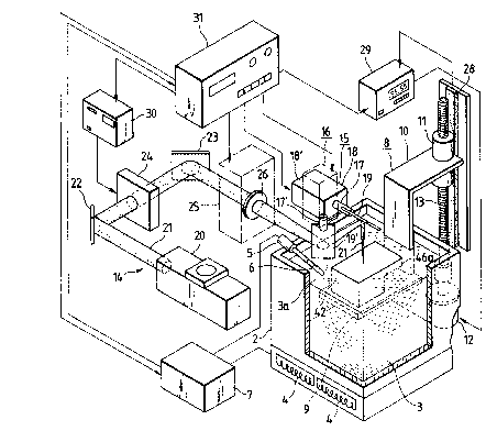
Referring to Figs. 1 to 3, the embodiment has a
vessel 2 in which liquid photosetting resin 3 is
stored. The vessel 2 is made in its entirety of
electrically conductive material or made of both
insulating material and electrically conductive
material in such a manner, for example, that a main
~~~~9 i~.
-6-
body of the vessel 2 is made of insulating material
and the whole or a part of the outer and inner
surfaces is covered by a thin layer of metallic
material, such as aluminum.
The liquid photosetting resin 3 is required to
be solidified by exposure to a light beam and also to
be hardened on the previously solidified resin. A
suitable resin can be selected from the group
including ultraviolet-ray-setting denatured acrylate,
denatured polyurethane methacryl, oligoethyl
acrylate, urethane acrylate, epoxy acrylate, and
photosensitive polyimide.
The vessel 2 is provided at its bottom portion
with a heating arrangement comprising a plurality of
coils 4 for high frequency induction heating. When a
high frequency current is supplied to the coils 4,
magnetic fluxes from the coils 4 act on a portion of
the vessel 2 made of electrically conductive material
so that an eddy current is produced therein by means
of electromagnetic induction. Consequently, the
vessel 2 generates Joule heat caused by eddy current
loss in the portion of the vessel 2 made of
electrically conductive material and thereby the
liquid photosetting resin 3 stored in the vessel 2 is
heated to have reduced viscosity.
In the case where the vessel 2 or its inner or
outer surfaces are made entirely of electrically
conductive material, the coils 4 for high frequency
induction heating can be disposed at any position
close to the inner or outer surface of the vessel 2.
Further, it is possible to provide a wall made of
ins~.alating material between the coils 4 and the
vessel 2 so as to form an explosion-proof bulkhead
isolating the coils 4 from the liquid photosetting
resin 3.
The embodiment also has a temperature sensor 5
~~0 ~95~.
for detecting the temperature of the liquid
photosetting resin 3 stored in the vessel 2 and
producing a detection output signal representing the
detected temperature. The temperature sensor 5 is
mounted on the vessel 2 and provided with a sensing
probe 6 immersed in the liquid photosetting resin 3
at its surface 3a.
The detection output signal obtained from the
temperature sensor 5 is supplied to a temperature
controller 7 connected to the coils 4 for high
frequency induction heating. The temperature
controller 7 is operative to control the high
frequency current supplied to the coils 4. By this
means the high frequency induction heating to the
vessel 2 is carried out in response to the detection
output signal from the temperature sensor 5 so as to
cause the liquid photosetting resin 3 stored in the
vessel 2 to be heated at a predetermined desirable
temperature.
The temperature controller 7 is operative also
to send a command signal to an operation controller
31, which is described in detail later, for
preventing the thxee-dimensional object producing
process from being started when the surface
temperature of the liquid photosetting resin 3 is
lower than a predetermined lower limit and for
causing the process to stop when the surface
temperature of the liquid photosetting resin 3 is
higher than a predetermined upper limit.
Accordingly, the three-dimensional object
producing operation is controlled by the operation
controller 31 so as not to be started before the
liquid photosetting resin 3 stored in the vessel 2
comes to have its viscosity lower than a
predetermined relatively low value and the apparatus
2~0 ~JS~.
_$_
is prevented from becoming uncontrollable when the
temperature of the liquid photosetting resin 3 at its
surface 3a is excessively increased for some abnormal
reason.
A temperature range including the predetermined
lower limit and the predetermined upper limit is
determined in accordance with temperature
characteristic in viscosity of the liquid
photosetting resin 3. In the case where the
ultraviolet-ray-setting denatured acrylate is used as
the liquid photosetting resin 3, the temperature
range is selected to be about 30°C to 50°C.
An elevating device 8 which has an upper plate
portion 10 provided with a fixed nut 11 engaging with
a screw shaft 13 is positioned alongside the vessel
2. The screw shaft 13 is driven to rotate by a
stepping motor 12 and therefore the elevating device
8 is moved up and down selectively step by step with
a predetermined pitch along the screw shaft 13.
Attached to the upper plate 10 is a lower, plate-like
stage 9 which can be immersed into the liquid
photosetting resin 3 stored in the vessel 2
selectively, step by step with the predetermined pitch
in accordance with the movements of the elevating
device 8.
The elevating device 8 also has a position
sensor 28 extending along the screw shaft 13. The
position sensor 28 is operative to detect positions
of the elevating device 8 in the vertical direction
and to produce a detection output signal representing
the detected position. The detection output signal
obtained from the position sensor 28 is supplied to
an elevating device controller 29 which controls the
rotation of the stepping motor 12 in accordance with
the detection output signal from the position sensor
~:~0 i:~5~.
_g-
28 so that the position of the elevating device 8 in
the vertical direction is controlled.
Further, an optical arrangement 14 for
generating and swinging a light beam, which includes
a light beam source 20 and light beam scanners 15 and
16, is provided. The light beam scanner 15 comprises
a shaft 17, extending horizontally and driven to
rotate by a mirror driver 18, and a mirror 19 mounted
at the end of the shaft 17 for causing a light beam
21 generated by the light beam source 20 to scan the
surface 3a of the liquid photosetting resin 3 stored
in the vessel 2 in a first scanning direction
indicated by arrows AR in Fig. 2. The light beam
scanner 16 comprises a vertically extending shaft
17', driven to rotate by a mirror driver 18', and a
mirror 19' mounted on the end of the shaft 17' for
causing the light beam 21 to scan the surface 3a of
the liquid photosetting resin 3 stored in the vessel
2 in a second scanning direction perpendicular to the
first scanning direction in a horizontal plane. The
rotating mirror 19 is disposed just above the plate-
like stage 9 in the liquid photosetting resin 3
stored in the vessel 2.
The light beam source 20 comprises, for example,
an argon laser for generating a laser light beam with
a wavelength of 360 nanometers or a helium-neon laser
for generating a laser light beam with a wavelength
of 325 nanometers. The light beam 21 generated by
the light beam source 20 is reflected by a mirror 22
to pass through an acoustooptic modulator 24 and is
reflected further by a mirror 23 to be incident
through a focusing device 25, having a focus lens 26,
upon the rotating mirror 19' of the light beam
scanner 16. The light beam 21 is directed to the
mirror 19 of the scanner 15 which causes the beam 21
to be incident upon the surface 3a of the liquid
~~OWS~,
-lo-
photosetting resin 3 stored in the vessel 2. The
light beam 21 scans the resin surface by the
movements of the rotating mirror 19' of the light
beam scanner 16 and the rotating mirror 19 of the
light beam scanner 15.
The acoustooptic modulator 24 is operative to
modulate the intensity of the light beam impinging
upon the mirror 23 in accordance with a modulating
signal supplied thereto and the focusing device 25 is
operative to focus the light beam on the surface 3a
of the liquid photosetting resin 3 stored in the
vessel 2.
With such an optical arrangement 14, a partial
area of the surface 3a of the liquid photosetting
resin 3 stored in the vessel 2, which is spreading
below the rotating mirror 19, is scanned by the light
beam 21 reduced in size to a beam spot of a
predetermined small size in both of the first and
second scanning directions which are perpendicular to
each other.
The operation controller 31 is operative to
control each of the light beam scanners 15 and 16,
the focusing device 25, the elevating device
controller 29, and a modulating signal generator 30
for supplying the acoustooptic modulator 24 with the
modulating signal. A control system including the
operation controller 31, light beam scanners 15 and
16, focusing device 25, elevating device controller
29 and modulating signal generator 30 is shown in
Fig. 3 in the form of a block diagram.
Referring to Fig. 3, a beam position control
circuit 35 including a memory 33 arid a modulator 34
is provided. The memory 33 is connected with a
designing device, e.g. a computer operating with
computer aided design software, for programming data
for producing a plurality of horizontally sliced
2~D0 ~tJ i~.
-11-
pieces of a three-dimensional object so that the data
programmed by the designing device is temporarily
stored in the memory 33. The modulator 34 is
operative to convert the data of each of the
horizontally sliced pieces of the three-dimensional
object, which is read from the memory 33, into
coordinate data representing positions on each of the
horizontally sliced pieces of the three-dimensional
object in the first and second scanning directions,
respectively. The coordinate data obtained from the
modulator 34 is supplied to each of two digital to
analog (D/A) converters 36a and 36b and a focus lens
driving circuit 40.
The D/A converter 36a converts the coordinate
data from the modulator 34 into a first scanning
signal corresponding to successive positions on each
of a plurality of first parallel lines extending in
the first scanning direction on each of the
horizontally sliced pieces of the three-dimensional
object and a second scanning signal corresponding to
successive positions on each of a plurality of second
parallel lines extending in the second scanning
direction on each of the horizontally sliced pieces
of the three-dimensional object. The first and
second scanning signals obtained from the D/A
converter 36a are supplied to a gate 37a by which the
first scanning signal or the second scanning signal
is selected to pass therethrough to the mirror driver
18 of the light beam scanner 15.
The D/A converter 36b converts the coordinate
data from the modulator 34 into a third scanning
signal corresponding to positions of the first
parallel lines on each of the horizontally sliced
pieces of the three-dimensional object in the second
scanning direction and a fourth scanning signal
corresponding to positions of the second parallel
200951.
-12-
lines on each of the horizontally sliced pieces of
the three-dimensional object in the first scanning
direction. The third and fourth scanning signals
obtained from the D/A converter 36b are supplied to a
gate 37b by which the third scanning signal or the
fourth scanning signal is selected to pass
therethrough to the mirror driver 18' of the light
beam scanner 16.
In summary, the first scanning signal represents
positional information along the first parallel
lines, the second scanning signal represents
positional information along the second parallel
lines, the third scanning signal represents the
positions of the first line in the second scanning
direction and the fourth scanning signal represents
the positions of the second scanning lines in the
first scanning direction.
The gates 37a and 37b are controlled by a
scanning direction switching circuit 38 so as to
alternately be in a first state wherein the first
scanning signal is selected by the gate 37a and the
third scanning signal is selected by the gate 37b and
in a second state wherein the second scanning signal
is selected by the gate 37a and the fourth scanning
signal is selected by the gate 37b. This switching
takes place for each period of time in which the
coordinate data of each horizontally sliced piece of
the three-dimensional object are read from the memory
33.
Therefore, the light beam 21 is caused by the
rotating mirrors 19 and 19' to be incident upon the
resin surface 3a. Alternately during each period of
time wherein the coordinate data of each horizontally
sliced piece of the three-dimensional object are
obtained from the modulator 34, the light beam 21
repeatedly performs a first line scanning in the
W:~0 ~'J51.
-13-
first scanning direction or a second line scanning in
the second scanning direction all over the partial
area of the resin surface 3a.
The focus lens driving circuit 40 is operative
to cause the focusing device 25 to control the
position of the focus lens 26 so as to focus the
light beam 21 upon the resin surface 3a in response
to the coordinate data obtained from the modulator
34.
The programmed data read from the memory 33 are
also supplied to an acoustooptic modulator driving
circuit 39. The acoustooptic modulator driving
circuit 39 is operative to control the modulating
signal generator 30 to produce a modulating signal
which varies in response to the programmed data
representing each of the first or second parallel
lines on each of the horizontally sliced pieces of
the three-dimensional object.
Further, the coordinate data obtained from the
modulator 34 is also supplied to a stepping motor
driving circuit 41. The stepping motor driving
circuit 41 is operative to control the elevating
device controller 29 to drive the stepping motor 12
in such a manner that the elevating device 8 is moved
to put the plate-like stage 9 at a position lower by
one stepping pitch from the resin surface 3a (this
position is referred to as an initial position) so
that a thin layer of the liquid photosetting resin 3
is provided on the plate-like stage 9 at the
beginning of the three-dimensional object producing
operation. Thereafter the elevating device 8 is
moved down to descend the plate-like stage 9 by one
stepping pitch whenever the coordinate data of each
horizontally sliced piece of the three-dimensional
object has been completely obtained from the
modulator 34.
~~?0 X951.
-14-
With the embodiment described above, a
three-dimensional object 42 shown in the exploded
form in Fig. 4 is produced through the processes as
will now be explained.
First, an operation starting signal is supplied
to the operation controller 31. If the temperature
of the liquid photosetting resin 3 at its surface 3a
is lower than the predetermined lower limit, the
three-dimensional object producing operation is not
started regardless of the supply of the operation
starting signal to the operation controller 31 and
the high frequency current is supplied to the coils 4
for high frequency induction heating in order to
cause the vessel 2 to be subjected to high frequency
induction heating and thereby to heat the liquid
photosetting resin 3.
When it is detected by the temperature sensor 5
that the temperature of the liquid photosetting resin
3 at its surface 3a has become equal to or higher
than the predetermined lower limit, the temperature
controller 7 operates to cause the operation
controller 31 to start the three-dimensional object
producing operation. The elevating device 8 is moved
to put the plate-like stage 9 at the initial position
and the first thin layer of the liquid photosetting
resin 3 is provided on the plate-like stage 9.
Then, the light beam 21 caused by the rotating
mirrors 19 and 19' to be incident upon the resin
surface 3a begins the first line scanning in the
first scanning direction on the first thin layer of
the liquid photosetting resin 3 provided on the
plate-like stage 9 repeatedly all over the surface of
the first thin layer of the liquid photosetting resin
3. This first scanning takes place during a period
of time in which the coordinate data of the first
horizontally sliced piece of the three-dimensional
~~0~95~1.
-15-
object 42 is obtained from the modulator 34. In this
way the first thin layer of the liquid photosetting
resin 3 on the plate-like stage 9 is hardened to form
a solidified layer of hardened resin. As a result of
this, the first solidified layer 43~ as shown in Fig.
4 is formed in the liquid photosetting resin 3. In
Fig. 4, dot-dash lines 44 indicate the first line
scannings by the light beam 21.
After the first solidified layer 43~ has been
formed, the elevating device 8 is moved down to
descend the plate-like stage 9 by one stepping pitch
so that the first solidified layer 43~ formed on the
plats-like stage 9 is moved downward into the liquid
photosetting resin 3 and a second thin layer of the
liquid photosetting resin 3 covers the first
solidified layer 43~. Since the vessel 2 is subjected
to the high frequency induction heating so as to keep
the liquid photosetting resin 3 at the predetermined
temperature so that the viscosity is sufficiently
reduced, the liquid photosetting resin 3 quickly
flows onto the first solidified layer 43~ to form the
second thin layer of the liquid photosetting resin 3.
Then, the light beam 21 caused by the rotating
mirrors 19 and 19' to be incident upon the resin
surface 3a repeatedly perform the second line
scanning in the second scanning direction on the
second thin layer of the liquid photosetting resin 3
provided on the first solidified layer 43~ all over
the surface of the second thin layer of the liquid
photosetting resin 3. This is done during a period
of time in which the coordinate data of the second
horizontally sliced piece of the three-dimensional
object 42 is obtained from the modulator 34. In this
manner the second thin layer of the liquid
photosetting resin 3 provided on the first solidified
layer 43~ is hardened to form a new solidified layer
~: ~~D~95~.
-16-
of hardened resin fixedly superimposed on the first
solidified layer 43~. Accordingly, a second
solidified layer 432 as shown in Fig. 4 is formed to
be fixedly superimposed on the first solidified layer
43~ in the liquid photosetting resin 3. In Fig. 4,
dot-dash lines 45 indicate the second line scannings
by the light beam 21.
Further, after the second solidified layer 432
has been formed, the elevating device 8 is moved down
again to descend the plate-like stage 9 by one
stepping pitch so that the first and second
solidified layers 43~ and 432 formed on the plate-
like stage 9 are moved downward into the liquid
photosetting resin 3 and a third thin layer of the
liquid photosetting resin 3 coats the second
solidified layer 432.
After that, the light beam 21 caused by the
rotating mirrors 19 and 19' to be incident upon the
resin surface 3a repeatedly performs the first line
scanning in the first scanning direction on the third
thin layer of the liquid photosetting resin 3
provided on the second solidified layer 43Z all over
the surface of the third thin layer of. the liquid
photosetting resin 3. This is accomplished during a
period of time in which the coordinate data of the
third horizontally sliced piece of the three-
dimensional object is obtained from the modulator 34.
The foregoing steps are repeated until the last
solidified layer 43" as shown in Fig. 4 is formed.
Through the processes described above, the first
to last solidified layers 43~, 432, 433, 434,
43g, - - - - - 43".3, 43~.Z, 43".~ and 43" are integrally
formed in a stack as shown in Fig. 4 and thereby the
three-dimensional object 42 which is made of
laminated, hardened resin is obtained.
;~~~ 5951.
-17-
Since the odd-numbered solidified layers (431,
433, 435, - - - ) are formed with the first beam
scanning in the first scanning direction and the
even-numbered solidified layers (432, 434, 436, _ _ _)
are formed with the second beam scanning in the
second scanning direction perpendicular to the first
scanning direction, the surface of a side portion 46
is smoothly formed and further bending deformations
of the respective solidified layers resulting from
volume contractions caused during solidification are
not uniform in direction so that even a projecting
portion 46a is prevented from bending badly.
Fig. 5 shows another embodiment of apparatus for
producing a three-dimensional object according to the
present invention. In Fig. 5, the devices, members
and portions corresponding to those of Fig. 2 are
marked with the -same references and further
description thereof will be omitted.
In the embodiment shown in Fig. 5, the liquid
photosetting resin 3 is supplemented from a resin
reservoir 47 provided on the vessel 2 to supply resin
to or store resin overflow from the vessel 2 to allow
for volume contraction of the liquid photosetting
resin 3 resulting from solidification of the liquid
photosetting resin 3 on the plate-like stage 9.
In the case of the embodiment shown in Fig. 5,
the resin surface 3a is kept at a constant level
regardless of volume contraction of the liquid
photosetting resin 3 resulting from solidification of
the liquid photosetting resin 3 on the plate-like
stage 9. This results in the advantages that the
control of the elevating device 8 fox positioning the
plate-like stage 9 properly in the liquid
photosetting resin 3 is easily carried out and the
temperature of the liquid photosetting resin 3 is
accurately detected by the temperature sensor 5.
2~0 5953.
-is-
Although the present invention has been shown and
described with respect to preferred embodiments,
various changes and modifications which are obvious
to a person skilled in the art to which the invention
pertains are deemed to lie within the spirit and
scope of the invention.