Note : Les descriptions sont présentées dans la langue officielle dans laquelle elles ont été soumises.
Z00601~
~UIIV~:h . I ~.~ t'~bTR AND TnAn t~ARRT~R DEVICE
BA~ ;KouNu OF T~P INVENTION
1. Field o~ ~h~ invention:
The present invention relates to a
multipurpose device that can be converted either (a)
lO into a carrier attachable to the back of a user
person for load carrying purposes, or (b) into a
chair for the user person.
15 2. Brief descriDtion of the Drior art:
United States patent 2, 480, 402 granted to
W. E~. ELSTON on August 30, 1949 proposes a
convertible device of this type. More specifically,
20 this patent describes a convertible boat 'chair and
load carrier device.
This prior art device can f irst be
converted into a chair attachable to a tranverse boat
25 seat to allow the user person to sit in the boat both
safely and comfortably.
The seat and the back of ELSTON`s chair can
also be aligned with each other in the same plane to
30 convert it into an outboard motor carrier. A harness
is secured to the so obtained carrier to enable the
user person to attach it on hi6 back. A motor
mounting support is also fixed to the carrier to
support the outboard motor while it is transported.
_ _ _ _ ... . , . . .. . .. .. , . , _
20060~a~
A first drawback of ELSTON`s device is its
lack of versatility. Indeed, it is designed to carry
only an outboard motor.
Another drawback of ELSTON`s device is its
compleYity, which increases the manufacturing costs.
It comprises numerous parts each having a different
function. In particular, separate members form the
10 seat of the chair and the outboard motor mounting
support .
OBJECTS OF 'T'~R INVRNTION
The main obj ect of the present invention is
therefore to eliminate the above discussed drawbacks
of the prior art by providing a convertible chair and
load carrier device which i5 (a) versatile as it can
20 be used to carry loads of different types, and (b)
simple in construction so that it can be manufactured
at low cost using conventional methods.
Another object of the present invention is
25 a convertible chair and load carrier device of which
a single member forms either a member for supporting
loads or the seat of a chair.
200601 4
,~TTMMARY ~F TTTT~' TNVF.NTIt)N
More particularly, the subj ect invention
is ~ nr~rnPfl with a convertible chair and load carrier
5 device comprising separable dorsaI member and load
support member, the dorsal member being, in use,
generally vertical and having front and rear opposite
faces, and the load support member having first and
second opposite faces and a proximate end;
means for attaching the dorsal member on
the back of a user person with the front face thereof
resting on the back of the user person;
the dorsal member and the proximate end of
the load support member being respectively provided
15 with first and second, mutually mating connecting
systems, wherein the second connecting system is
capable of detachably engaging the f irst co~necting
system to fixedly secure the load support member to
the dorsal member in a f irst position in which the
2 0 load support member OEtends rearwardly of the dorsal
member and is generally perpendicular to the dorsal
member to f orm an L- shaped load carrier device, in
which first position the irst face of the load
support member is an upper face and is generally
25 horizontal 50 that a load to be carried by the user
person can be disposed thereon, and wherein the second
connecting system is capable of detachably engaging
the f irst connecting system to f ixedly secure the load
' , ,
200601 4
eupport member to the dorsal member in a second
position in which the load support member extends
forwardly of the dorsal member to form a chair having
a seat constituted by the second face of the load
5 support member and a back constituted by the front
face of the dorsal member.
The present invention also relates to a
lO convertible chair and load carrier device, comprising:
a dorsal member being, in use, generally
vertical and having front and rear, opposite faces;
means for attaching the dorsal member on
the back of a user person with the front face thereof
15 resting on the back of the user person;
a load support member with f irst and
second opposite faces, and with a proximate end; and
means f or securing the proximate end of
the load support member to the dorsal member either in
20 (a) first position in which the load support ~nember
extends rearwardly of the dorsal member and is
generally perpendicular to the dorsal member to form
an I--shaped load carrier device, wherein in the first
position the first face of the load support member is
25 an upper face and is generally horizontal so that a
load to be carried by the user person can be dispoaed
thereon and (b) a second position in which the load
support member extends f orwardly of the dorsal memoer
~,
20060 ~ ~
3b
to form a chair having a seat constituted by the
second face of the load support member and a back
constituted by the front face of the dorsal member;
the means for securing the proximate end
of the load support member to the dorsal member
comprising means for separating the proxlmate e~d of
the load support member from the dorsal member;
the convertible chair and load carrier
device having two sides, and the means for securing
the proximate end of the load support member to the
dorsal member is the :Eirst or second position
comprises on each side of the device:
(i) the dorsal member formed with a lower
projection;
(ii) an open slot made in the lower
pro i ection of the dorsal memberi
(iii) fastener means including a rod
traversing the open slot for securing the proximate
end of the load support member to the dorsal member;
2 o ( iv) a groove made in one of the lower
projection of the dorsal member and prox~mate end of
the load support member; and
(v) a stud formed on the other of the
lower pro~ection of the dorsal member and proximate
2~ end of the load support member, the stud being
structured to slide into the groove.
i
A
20060 1 4
3c
In accordance with the present invention,
there is provided a convertible chair and load carrier
device, comprising:
a generally vertical dorsal member with front and rear, opposite faces, and with a lower end;
means for attaching the dorsal member on
the back of a user person with the front face thereof
resting on the back of the user person;
a load support member with f irst and
10 second opposite faces, and with proximate and distal
ends; and
hinge means for hingedly attaching the
proximate end of the load support member to the lower
end of the dorsal member whereby the load support
15 member can-be pivoted about the dorsal member between
(a) a first position in which the load support member
extends rearwardly o~ the dorsal member and is
generally perpendicular to the dorsal member to form
an L-shaped load carrier device, wherein in the first
20 position the first face of the load support member is
an upper face and is generally horizontal 80 that a
load to be carried by the user person can be disposed
thereon, and (b) a second position in which the load
support member extend~ forwardly of the dorsal member
25 to form a chair having a seat constituted by the
second face of the Ioad support member and a back
constituted by the front face of the dorsal member;
20060 1 4
3d
the hinge means comprising means for
locking on the dorsal member the load support member
in its first position and means for locking on the
dorsal member the load support member in its second
position.
In accordaAce with the present invention,`
there is further provided a convertible chair and load
carrier device, comprising:
a dorsal member with first and second
opposite f aces;
means for attaching the dorsal member on
the back of a user person with the first face thereof
resting on the back of the u3er person;
a load support member with f irst and
second opposite faces; and
means for securing the load support member
to the dorsal member either in f irst or second
positions;
wherein in its first position the load
support member is capable of supporting a load to
thereby allow the user person to carry it on his back,
and wherein in the second position of the load support
member, the load support member forms the seat of a
chair and the dorsal member thQ back of that chair;
wherein the means for securing the load support member
to the dorsal member comprises:
A
20060 1 4
3e
means for pivoting the load support member
about the dorsal member between the f irst and second
positions; and
means for locking on the dorsal member the
5 load support member in el~her one of its first and
second positions; and
wherein the convertible chair and load carrier device
has two sides, and the pivoting means comprises on
each side of the device:
the dorsal member formed with a lower
projection defining opposite inner and outer faces;
a pair of overlying cylindrical holes
formed in one of the inner and outer faces of the
lower projection, the overlying holes having a bottom;
an oval slot interconnecting the bottom of
the holes with the other of the inner and outer faces
of the lower pro ~ection, the slot extending in the two
overlying holes;
a threaded, nut-like fastener fixedly0 secured to the load support member;
a rod with a ~irst threaded end and with
a second end;
a knob f ixedly secured to the second end
of said rod and comprieing a cylindrical portion
25 structured to fit irL either one of the overlying
holes;
wherein the cylindrical portion of the
knob can be fitted i~ either one o~ the cylindrical
.~
.
20060 1 ~
3~
holes with the rod traversing the oval slot and with
the t~hreaded end of the rod engaging the ~ut-like
f astener .
2006014
The objects, advantages and other features
of the present invention will become more apparent
upon reading of the following non restrictive
5 description of preferred embodiments thereof, given
by way of example only with reference to the
accompanying drawings.
RRT~ ES~RTPTION OF THE ~RAWINGS
In the ~rppn~lpd drawings:
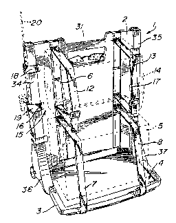
Figure 1 is a perspective view of a
convertible chair and load carrier device according
to the invention, converted into a load carrier;
Figure 2 is a perspective view of the
device of Figure l, converted into a chair;
Figure 3 is a side elevation view of the
convertible chair and load carrier device of Figure6
l and 2, comprising a dorsal member on which is
pivotally mounted a load support member;
Figures 4 and 5 are respectively side and
top views, partially cross sectional, of the pivotal
connections between the dorsal member and the load
support me~ber of the convertible device of Figures
1, 2 and 3;
Figure 6 i8 a cross sectional view, taken
along axis A-A of Figure 2, of one of the shoulder
straps of a harness allowing the user person to
_ _ _ _ _ _ _ ,, ,, , , , _ , . ,,, , , . _ , . _ _, ..... .... . .
Z0060i~
attach on his back the dorsal member of the
convertible chair and load carrier device in
accordance with the present invention;
Figures 7 and 8 are perspective views of
other : o~l; r -nts of the convertible chair and load
carrier device of the invention, including a pair of
arcuate, strap-like and subtantially rigid members
for at~rh i n~ the device on the back of the user
per60n;
Figure 9 is a perspective view showing the
device of the invention converted into a load carrier
and provided with a removable parkc~k-like canvas
cover for protecting the carried load against bad
weather; and
Figure 10 is a partially cross sectional
elevation view of another embodiment of the
r- '-n;c:~l connection between the dorsal and load
support members of the convertible chair and load
carrier device in accordance with the present
invention .
nT~T~TT.Tn ~)T~T~TPTION OF rl'~lT` ~K~ I) EMR~-~TMT'NTS
As illustrated in Figures 1 and 2, the
convertible chair and load carrier device, generally
identified by the reference numeral 1, comprises a
dorsal member 2 and a load support member 3.
In Figure 1, the device 1 is converted into
a load carrier. The load support member 3 is then in
_ _ _ _ . _
20060~4
a first, generally horizontal position with an upper
face 4 that is hollowed out to receive a load such as
a marine battery S (shown in dashed lines) for
powering an electric outboard motor. ~he dorsal
5 member 2 which is generally vertical is formed with a
plurality of horizontal slots such as 6. A pair of
straps 7 and 8 pass into two of these slots 6, into
vertical grooves 9 and 10 formed on the face ll of
the dorsal member 2 (Figure 2), and under the load
10 support member 3 to encircle the battery 5 and
thereby retain it onto the member 3.
Another pair of straps 12 and 13 can also
be used to attach for example a fly box 14 (shown in
15 dashed lines) on the face 15 of the dorsal member 2.
Each strap 12 ,13 pass through a pair of horizontal
slots 6 and in a respective one of the grooves 9 and
10 .
On both side of the dorsal member 2 are
also formed a plurality of vertical slots such as 16
and 17. As an example, short straps such as 18 and
19 pass through a pair of respective slots 16 and
encircle a fishing rod 20 (illustrated in dashed
lines) to attach the latter rod on the dorsal member.
As can be appreciated from Figure 1 of the
attached drawings, the device 1 of the invention is
very versatile and can be used to carry a plurality
of loads of different types.
As it is apparent f rom Figures 2 and 3, the
face 11 of the dorsal member 2 is arcuate to present
a concavity adapting the contour of the back of the
2006014
user person. As the straps 7, 8, 12 and 13 are
located in the grooves 9 and 10, they cause no
discomfort to the user person. In order to attach
the device 1 on the user person with the face 11 of
5 the dorsal member 2 resting on his back, a harness
including a pair of shoulder straps 21 and 22 as well
as a belt 23 is provided. As shown in Figure 6 which
is a cross sectional view of the shoulder strap 22
taken along axis A-A (Figure 2), each shoulder strap
21, 22 is padded with soft material 24 for the user's
comfort. For a better support of the device 1 by the
shoulders of the user person, a flat, substantially
rigid, elongated and arcuate member 25 is inserted in
a compartment formed in the shoulder strap 22 through
a slot 26 (Figure 2). As shown in dashed lines in
Figure 2, another flat, substantially rigid,
elongated and arcuate member 27 is inserted into the
shoulder strap 21 through a slot 28. The belt 23
also comprises inner pads 29 and 30 again for the
user's comfort. Each belt 21,22 has its upper end
secured to the upper end of the dorsal member 2, and
its lower end attached to the belt 23. The two ends
of the belt 23 are also secured to the respective
sides of the dorsal member.
The harness of the convertible chair and
load carrier device 1 is otherwise conventional and
accordingly it will not be further described. In
particular, the fixation of the shoulder straps 21
and 22 and of the belt 23 to the dorsal member 2 can
be carried out in a plurality of different ways known
to those skilled in the art. The present invention
is obviously not limited to the type of such
f ixation .
2006014
To help in handling the device 1 of the
invention, the dorsal member 2 comprises an upper
handle 3 1.
Figure 2 of the drawings illustrates the
device 1 converted into a chair. The load support
member 3 is then in a position 180 degrees apart from
its position as shown in Figure 1, where the device 1
10 is converted into a load carrier. In the position
illustrated in Figure 2, the member 3 has an upper
face 32 formed as a seat. The member 3 therefore
constitutes the seat of the chair and the dorsal
member 2 its back. Of course, the buckle 33 of the
15 belt 2 3 can be detached and the harness moved away to
clear the chair.
The connections which enable pivoting of
the member 3 on the dorsal member 2 between its
20 position shown in Figure 1 and that of Figure 2 will
now be described in detail with reference to Figures
3, 4 and 5 of the 2ppended drawings.
The dorsal member 2 is formed with two
25 generally vertical side posts 34 and 35 each
comprising a respective lower and triangular
projection 36,37 (Figures 1 and 2). As illustrated
in Figure 3, the member 3 can be pivoted between the
two projections 36 and 37. More specifically, a
30 first pivotal connection is established between the
projection 36 and the member 3, while a second,
similar pivotal connection is established between the
projection 37 and the load support member 3. In the
following description, only one of these two
2006014
g
connections will be ~ d, that is the one
CUL1~ r1;nrJ to the projection 36, keeping in mind
that the other pivotal connection is similar but
symmetrical with respect to a central plane of
5 y - tL~ of the convertible chair and load carrier
device 1.
The pivotal connection comprises a pair of
overlying cylindrical holes 38 and 39 formed on the
10 outer face of the projection 36 (Figures 4 and 5).
The overlying holes 38 and 39 have a bottom 40
interconnected to the inner face of the projection 36
through an oval slot 41. The pivotal connection also
comprises a knob 42 secured at one end of a metallic
15 rod 43 which is threaded at the other end. The knob
42 is formed with a cylindrical portion 44 structured
to fit in either one of the overlying holes 38 and
39. The rod 43 traverses the slot 41 and has its
threaded end screwed in a fastener 45 such as a nut,
20 a threaded tube section, etc..., ~mh~ in the
material of the load support member 3. Also, a
tubular spacer 46 is mounted onto the rod 43 between
the cylindrical portion 44 and the fastener 45.
When the device 1 is converted into a load
carrier as shown in Figure 1, the cylindrical portion
44 of the knob 42 is inserted in the hole 38 and a
protuberance 49, integral with the member 3, is mated
with a cavity 50 formed in the rear end of the
pro~ection 36. Also, as shown in Figure 4, a
laterally proj ecting stud 57, integral with member 3,
rests on the upper wall of a cavity 59 formed into
the material of the projection 36. This arrangement
makes the load support member 3 stationary with
. . _ _ _ . _ . . _ _ _ _ _ _ _ _ . . .
200601'~
respect to the dorsal member 2. Of course, a similar
arrangement is present on the other side of the
device 1.
When the device 1 is converted into a chair
as shown in Figure 2, the cylindrical portion 44 of
the knob 42 is inserted in the cylindrical hole 39
and the stud 57 is mated with a cavity 58 formed in
the front end of the projection 36. Again, this
arrangement makes the member 3 stationary with
respect to the dorsal member 2. Obviously, a similar
arrangement is provided on the other side of the
convertible chair and load carrier device.
In order to convert the device 1 from a
load carrier to a chair, the following operations are
carried out, obviously on the two sides of the
convertible chair and load carrier device;
- the knob 42, fitted in hole 38, is
unscrewed (see arrow 47 in Figures 3 and 5) until its
cylindrical portion 44 is completely situated outside
the hole 38 (see the dashed lines 60 in Figure 5)
whereby the tubular spacer 46 can slide into the slot
41;
- the load support member 3 is then pulled
in the direction 48 shown in Figures 3 and 5 until
the rod 43 and spacer 46 reach their position shown
by the dashed lines 61 in Figure 5, in which the
protuberance 49 disengages the cavity 50 (the cavity
59 is large enough to enable movement of the stud 57
as the member 3 is pulled as evidenced in FigureS 4
and 5 );
2U0601~
11
- the load support member 3 is pivoted in
the direction indicated by the arrow 52 in FLgure 3
until it is generally vertical as illustrated in
dashed lines;
- the member 3 is translated in the
direction 54 (Figure 3) until the rod 43 and spacer
46 reach their initial position;
- the member 3 i8 again pivoted in the
direction indicated by the arrow 53 in Figure 3:
- it is then pushed in the direction 56 to
mate the stud 57 and cavity 58;
- the knob 42 is finally screwed to fit the
cylindrical portion 44 in the hole 39.
The device 1 is then converted into a
20 chair.
To convert the device 1 from a chair to a
load carrier, the inverse operations are carried out,
starting with the last operation and ending with the
25 first one. Such inverse operations will be apparent
to those skilled in the art without the need o~
enumerating the same,
In Figures 7 and 8, the harness o~ Figure 2
30 is replaced by a pair of elongated, substantially
rigid, arcuate and flat shoulder members 62 and 63.
These two flat members 62 and 63 are shaped to fit on
the respective shoulders of the user person to attach
the device 1 on his back. The arcuate members 62 and
~ Z006014
12
63 are wide enough to ensure the comfort of the user
person .
In accordance with a f irst embodiment as
5 illustrated in Figure 7, the shoulder members 62 and
63 are fastened to the dorsal member 2 through a
respective pair of screws 64, 65 .
In the embodiment of Figure 8, one end of
10 each shoulder member 62, 63 defines a first right
angle such as 66 rearwardly and then a second right
angle such as 67 downwardly. It is beleived to be
apparent that this shape of the ends of the shoulder
members enables easy removal of these members 62 and
15 63 from two of the vertical slots 6 in the dorsal
member 2 when the device 1 is used as a chair, and
easy installation of these shoulder members in the
slots 6 when the device 1 is used as a load carrier.
2 0 When the device 1 is converted into a load
carrier, a packsack-like canvas cover 70 (Flgure g~
can be f ixed to the device 1 to protect the carried
article or articles against bad weather, in
particular rain and snow. In the embodiment shown in
Figure 9, the cover 70 is secured to the device
through a plurality of press-studs such as 69
fastened to both the member 2 or 3 and the cover 70.
The press-studs 69 enable easy removal of cover 70 as
well as easy installation thereof on the device 1.
The cover 70 can of course be opened and closed by
means of a flap 68 attached through a pair of buckles
71 and 72. The convertible chair and load carrier
device 1 can then be used as a packsack.
Z006014
13
Figure 10 illustrates another embodiment
for the mechanical connection between the dorsal
member 2 and the load support member 3. More
specifically, a first groove 73 and a second groove
5 74 are formed on the inner face of each projection
36,37, as shown with respect to projection 37. A
front, straight open slot 75 and a rear, angular open
slot 76 are also formed in each projection 36,37. On
both sides of the member 3 an integral stud such as
10 77 i8 provided while a nut-like threaded fastener is
eM~ in this member 3 to receive the threaded
free end of a rod such as 78. Each rod 78 has a knob
79 fixedly secured at the end thereof opposite to its
threaded end.
In order to convert the device 1 into a
load carrier, the two rods 78 are slid into the
respective slots 76 while the two studs 77 are
inserted into the respective grooves 73. When the
20 studs 77 and the rods 78 are in their positions of
Figure 10 in the grooves 73 and the slots 76, the
knobs 79 are screwed to tighten the member 3 on the
dorsal member 2. To remove the load support member 3
from the member 2 one has only to loose the knobs 79
25 and slide the studs 77 in the grooves 73 and the rods
78 in the slots 76 in the opposite direction.
To convert the device 1 into a chair, the
member 3 is first turned upside down. The rods 78
30 are then slid into the front slots 75 while the studs
77 are inserted into the grooves 74. As the studs 77
and the rods 78 reach their positions of Figure 10 in
the grooves 74 and the slots 75, the knobs 79 and
threaded rods 78 are tightened. Again, one has only
xoo~
14
to loose the knobs 79 and slide the studs 77 in the
grooves 74 and the rods 78 in the slots 75 in the
opposite direction to remove the member 3 from the
dorsal member 2.
As can be appreciated, the load support
member 3 can be separated from the dorsal member 2 in
the embodiment of Figure 10.
It is apparent from the cross sections of
Figures 4, 5 and 10 that both the members 2 and 3 are
hollow and can advantageously be made of plastic
material through an adequate, conventional molding
process. Accordingly, the device 1 is capable of
15 floating when dropped in water so that it can be
easily recovered. It can even be capable of floating
when loaded provided that such load is not too heavy.
Although the present invention has been
20 described hereinabove with reference to preferred
embodiments thereof, such embodiments can be modified
at will, within the scope of the appended claims,
without departing from the nature of the subject
invention .