Note : Les descriptions sont présentées dans la langue officielle dans laquelle elles ont été soumises.
F-4886
~THOD OF FCC SPENT CATALYST STRIPPING FOR I~ROVED EFFICIENCY
AND REDUCED HYDROCARBON FLOW TO REGENERATOR
This invention relates to a method and apparatus for the
separation of entrained cracked products from a fluidized finely
divided solid catalyst in a fluidized catalytic cracking unit
(FCC). More particularly, it relates to an improved method and
apparatus for separating catalyst from a catalytically cracked
product in a catalyst stripper zone to minimize or substantially
eliminate flow of valuable cracked product to the regenerator.
The field of fluid catalytic cracking has undergone
significant improvements relating both to catalyst technology and to
mechanical process unit design. These advances have enabled
refiners to process heavier feedstocks as well as to increase the
total yields of gasoline and distillate. However, the significant
potential for process improvement resulting from eliminating or
substantially reducing flow of cracked products to the regenerator
has not been fully realized.
By way of background, the hydrocarbon conversion catalyst
usually employed in an FCC unit is preferably a high activity
crystalline zeolite catalyst of a fluidizable particle slze. The
catalyst is transferred in suspended or dispersed phase condition
generally upwardly through one or more riser conversion zones (FCC
cracking zones) providing a hydrocarbon residence time in each
conversion zone in the range of 0.5 to 10 seconds, and usually less
than 8 seconds. High temperature riser hydrocarbon conversions,
occurring at temperatures of at least 538C (1000F) or higher and
at 0.5 to 4 seconds hydrocarbon residence time in contact with the
catalyst in the riser, are desirable for some operations before
initiating separation of vapor phase hydrocarbon product materials
3~L6
F-4886 --2--
from the catalyst. Rapid separation of catalyst from hydrocarbons
discharged from a riser conversion zone is particularly desirable
for restricting hydrocarbon conversion time. I~ is also highly
desirable to strip hydrocarbon product materials from the catalyst
before the catalyst enters a regeneration zone. During the
hydrocarbon conversion step, carbonaceous deposits accumulate on the
catalyst particles and the particles entrain hydrocarbon vapors upon
removal from the hydrocarbon conversion step. The entrained
hydrocarbons are removed from the catalyst in a separate catalyst
stripping zone. Hydrocarbon conversion products separated from the
catalyst and stripped materials are combined and passed to a product
fractionation step. Stripped catalyst containing deactivating
amounts of carbonaceous material, referred to as coke, is ~hen
passed to a catalyst regeneration operation.
Coke deposited on deactivated FCC catalyst together with
entrained product which is carried over to the regenerator with the
deactivated catalyst is referred to by those skilled in the art as
"total delta carbon." For a given FCC unit design, at a fixed
catalyst circulation rate, an increase in total delta carbon is
accompanied by higher regenerator temperatures. Consequently, one
method of limiting FCC regenerator temperature is to reduce total
delta carbon by reducing carryover of cracked hydrocarbon product to
the regenerator.
Methods and systems for separating catalyst particles from
a gas suspension phase containing catalyst particles and hydrocarbon
vapors, particularly the separation of high activity crystalline
zeolite cracking catalysts, have been the subject of recent advances
in the art.
Anderson et al ~.S. Patent 4,043,899 discloses a method for
rapid separation of a product suspension comprising fluidized
catalyst particles and the vapor phase hydrocarbon product mixture,
by discharging the entire suspension directly from the riser
conversion zone into a cyclone separation zone. The cyclone is
63~6
F-4886 --3--
modified to include a separate cyclonic stripping of the catalyst
separated from the hydrocarbon vapors. In the method of Anderson et
al, the cyclone separator is modified to include an additional
downwardly extending section comprising a lower cyclone stage. In
this arrangement, catalyst separated from the gasiform material in
the upper stage, slides along a downwardly sloping baffle to the
lower cyclone where stripping steam is introduced to further
separate entrained hydrocarbon products from the catalyst recovered
from the upper cyclone. The steamed and stripped hydrocarbons are
passed from the lower cyclone through a concentric pipe where they
are combined with the hydrocarbon vapors separated in the upper
cyclone. The separated and stripped catalyst is collected and
passes from the cyclone separator by conventional means through a
dipleg.
Myers et al U.S. Patent 4,070,159 provides a separation
means whereby the bulk of catalyst solids is discharged directly
into a settling chamber without passing through a cyclone
separator. In this apparatus, the discharge end of the riser
conversion zoDe is in open communication with the disengaging
chamber such that the catalyst discharges from the riser in a
vertical direction into the disengaging chamber which is otherwise
essentially closed to the flow of gases. me cyclone separation
system is in open communication with the riser conversion zone by
means of a port located upstream from, but not near, the discharge
end of the riser conversion zone. A deflector cone mounted directly
above the terminus of the riser causes the catalyst to be directed
in a downward path so as to prevent the catalyst from abrading the
upper end of the disengaging vessel. me cyclone separator is of
the usual configuration employed in a catalytic cracking unit to
separate entrained catalyst particles from the cracked hydrocarbon
products so that the catalyst passes through the dipleg of the
cyclone to the body of the catalyst in the lower section of the
disengaging vessel, and the vapor phase is directed from this vessel
~6~6
F-4886 --4~-
to a conventional fractionation unit. There is essentially no net
flow of gases within the disengaging vessel beyond that resulting
from a moderate amount of steam introduced to strip the catalyst
residing in the bottom of the disengaging vessel.
It is also known to transfer thermal energy from the
regenerator to the reactor. Gross U.S. Patents 4,356,082 and
4,411,773 teach a fluid catalytic cracking (FCC) process and
apparatus wherein the heat balance between the reactor and the
regenerator of the FCC operation is partially uncoupled by
transferring at least a portion of thermal energy from the reactor
vessel riser to the regenerator vessel. The transfer of thermal
energy results in a higher regenerating temperature. The thermal
energy is recirculated to the upstream section of the reactor riser
through a regenerated catalyst having higher temperature. As a
result, the outlet of the reactor vessel is maintained at a
substantially constant temperature (538C (1000F)) and the rate of
conversion of the oil feed and the octane number of gasoline
produced in the process are increased.
Krug U.S. Patent 4,574,044 discloses a method for
increasing the overall efficiency of an FCC process by decreasing
the amount of valuable product burned in the regenerator.
Separation of catalyst from hydrocarbon product is enhanced by first
stripping the hydrocarbon product from the catalyst and then
conditioning the catalyst in the presence of steam at elevated
temperatures for a period of 1/2 to 30 minutes. The benefits of
this system include a reduction in coke make.
Owen et al U.S. Patent 4,689,206 teaches an apparatus for
~luid catalytic cracking (FCC) of a hydrocarbon feed in an open or
closed system, which includes a multi-stage stripper sys-tem, which
comprises a means for spinning a gasiform mixture of catalyst and
cracked hydrocarbons exiting from a riser, a first means for
stripping the spun gasiform mixture, and a means for deflecting the
gasiform mixture to separate catalyst from the cracked hydrocarbons.
~G3 lL~
-
F-4886 ~~5~~
Commonly-assigned U.S. Patent Application Serial Number
903,365 filed September 3, 1986, of Herbst et al discloses a
technique for improving the efficiency of a catalyst stripper
section by injecting an inert gas and heating the stripper section
by carrying out an exothermic reaction within the stripper.
FCC regenerators with catalyst coolers are disclosed in
U.S. Patents 2,377,935; 2,386,491; 2,662,050; 2,492,948 and
4,374,750 inter alia.
Briefly, the present invention improves stripping
efficiency in an FCC catalyst stripper is improved by indirectly
heating the stripper section with hot regenerated catalyst fluidized
in a stream of regenerator flue gas. ~lore particularly, the method
of the present invention comprises: mi~ing a hydrocarbon feed with a
regenerated catalyst in the lower section of a reactor riser;
passing the mixture through the length of the reactor riser under
conversion conditions whereby the hydrocarbon is catalytically
cracked and the catalyst is deactivated; separating the cracked
product from the deactivated catalyst; charging the deactivated
catalyst to a stripping zone; withdrawing the deactivated catalyst
from the stripping zone; regenerating the withdrawn deactivated
catalyst in a regeneration zone whereby a hot flue gas is generated;
withdrawing a portion of the regenerated catalyst; fluidizing the
regenerated catalyst in a stream of the hot flue gas; transferring
at least a portion of the thermal energy of the regenerated catalyst
and the hot flue gas to the stripping zone whereby the mi~ture of
hot flue gas and regenerated catalyst is cooled and the stripping
zone is heated.
The method may also include transferring thermal energy
from hot flue gas and regenerated catalyst to the stripping zone by
maintaining conduit means within the stripping zone and passing
regenerated catalyst fluidized in a stream of hot flue gas through
the conduit means at a flow rate such that the stripping zone is
heated to a temperature sufficient to enhance separation of catalyst
~63~6
F-4886 --6--
and hydrocarbon product. The cooled regenerated catalyst and flue
gas are then mixed wi~h hot regenerated catalyst and charged to the
reactor riser. Alternatively, the cooled regenerated catalyst and
flue gas may be returned to the regenerator.
The present invention also comprises an apparatus for
separating entrained hydrocarbon vapors from a fluidized catalyst
bed comprising a longitudinally extensive cylindrical reactor shell
having inlet and outlet ports; a cylindrical riser conduit extending
longitudinally through the reactor shell; a plurality of
frustoconical members attached to the inner surface of the reactor
shell; a plurality of frustoconical members attached to the outer
surface of the riser conduit; and conduit means extending through
the reactor shell for providing indirect heat exchange between a
fluidized mixture of hot flue gas and a finely divided solid flowing
through the conduit means and the gaseous stream containing solid
catalyst flowing around the outer surface of the conduit means.
The apparatus may further comprise a multiple-tube heat
exchanger positioned in the annular space between the outside
surface of the riser conduit and the inside surface of the reactor
shell~
The apparatus may further comprise flow control means for
controlling the regenerated catalyst and hot flue gas flow rates
through the tubes to maintain a desired temperature in the catalyst
stripper.
The present invention reduces coke loading on deactivated
catalyst by reducing the amount of valuable product carried over to
the regenerator. This lowers regenerator temperature for a given
catalyst circulation rate. Cooler regenerated catalyst permits
operation at an increased catalyst to oil ratio and consequently
increases conversion.
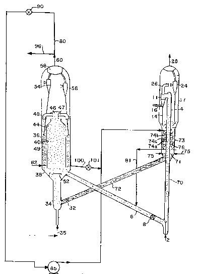
In the drawings, Figure 1 is a simplified schematic diagram
showing the major components of an FCC unit wherein regenerated
catalyst fluidized in a stream of flue gas provides thermal energy
to heat the catalyst stripper section.
3~L6
F-4886 ~~7~~
Figure 2 is a simplified schematic diagram showing an FCC
unit reactor riser and spent catalyst stripper including the novel
catalyst stripper design of the present invention.
In Figure 1, a hydrocarbon oil feed such as gas oil or
higher boiling material is introduced through a conduit 2 to the
bottom or upstream section of a riser reactor 70. Hot regenerated
catalyst is also introduced to the bottom section of the riser by a
standpipe 6 equipped with a flow control valve 8. A vapor liquid
suspension is formed in the lower bottom section of the riser 70 at
an elevated temperature at 525C to 650C (9~0F to 1200F) and is
usually at least 540C (1000F), depending on the degree of
hydrocarbon conversion desired and on the composition of the feed.
The suspension is formed in the bottom section of the riser and is
passed upwardly through the riser under selected temperature and
residence time conditions. Residence of the hydrocarbon charge
stock in the riser is usually between O.l and 15 seconds, typically
0.5 to 4 seconds, before the suspension passes through suitable
separating means, such as a series of cyclones ll rapidly effecting
separation of catalyst particles from vapor hydrocarbon conversion
products. Thus, in the apparatus shown in Figure 1, the suspension
is discharged from the riser 70 into one or more cyclonic separators
attached to the end of the riser and represented by a separator
means ll. Catalyst particles separated in the cyclone 11 pass
countercurrently in contact with stripping gas introduced by conduit
16 to a lower portion of the cyclone. ~IUS, the con~acted and
separated catalyst is withdrawn by a dipleg 14 for discharge into a
bed of catalyst in the lower section of the reactor.
The end of the riser 70 with attached separation means ll
as shown in Figure 1 is housed in the larger vessel 17 designated
herein as a receiving and catalyst collecting vessel. The lower
portion of ~he vessel 17 has generally a smaller diameter than the
upper portion thereof and comprises a catalyst stripping section 73
to which a suitable stripping gas, such as steam, is introduced,
63~
F-4886 --8--
e.g. by a conduit 75. The stripping section is provided with a
plurality of frustoconical baffles 74A, 74B and 74C (only three are
designated) over which the downflowing catalyst passes
countercurrently to upflowing stripping gas.
Hot flue gas is withdrawn from plenum section 58 of
regenerator vessel 36 through conduit 60. Control valve 9Q
positioned in line 80 sets the flowrate of hot flue gas flowing from
the regenerator vessel 36 to the stripping section 73. Hot
regenerated catalyst is withdrawn from the regenerator vessel 36
through line 100 which is equipped with control valve 101 and flows
into line 80 where it is fluidized in a stream of hot flue gas. The
fluidized mixture flows through line 80 into heat exchanger conduit
76 positioned inside the stripping section 73. I~hile line 80 is
illustrated as entering stripping section 73 near the top, it is to
be understood that the present invention encompasses both downflow
and upflow embodiments. Consequently, line 80 may alternatively be
positioned near the bottom of stripper section 73. A compressor 85
may optionally be installed in line 80 to facilitate flow of flue
gas and fluidized catalyst through line 81 into standpipe 6.
Once inside the stripper section 73, the conduit means may
comprise a heat exchanger conduit 76 passing helically between the
baffles, or the conduit may comprise a plurality o~ vertical or
horizontal tubes (not shown).
The fluidized mixture of flue gas and regenerated catalyst
enters the heat exchanger conduit 76 at between 650C and 760C
(1200F and 1400F) and leaves the stripping sec-tion at a
temperature between 590C and 710C (1100F and 1300F). The cooled
fluidized mixture from heat exchanger conduit 76 flowing through
line 81 flows into regenerated catalyst standpipe 6. Alternatively,
the cooled fluidized mixture may be returned to the regenerator. As
mentioned above, line 80 is positioned near the bottom for upflow
operation, then line 81 will be positioned near the top of stripper
section 73.
6~3~6
F-4886 ~~9~~
Regenerated catalyst and flue gas flowrates are controlled
to increase the temperature in the stripper section 73 sufficiently
to achieve enhanced separation be~ween catalyst and reaction
products in the stripper. This temperature increase should exceed
28C (50F)~
A cyclone 24 is provided in the upper portion of the vessel
16 for recovering stripped hydrocarbon products and stripping gas
from entrained catalyst particles. As is well known in the art,
there may also be provided a second sequential stage (not shown) of
catalyst separation for product vapors discharged from the separator
11 by a conduit 26.
Deactivated stripped catalyst is withdrawn from the bottom
of the stripping section at an elevated temperature which may vary
with individual unit operation but typically ranges between 560C
and 600C (1050F to 1100F), by a standpipe 72 equipped with a flow
control valve 32. The catalyst is then passed from the standpipe 72
into the bottom portion of a regenerator riser 34. A regeneration
gas is introduced into the bottom of riser 34 through a conduit 35.
The regeneration gas may comprise air or may optionally comprise
preheated air or oxygen supplemented air at 150C to 260qC (300F to
500F) and 270 kPa (25 psig) to 450 kPa (50 psig), typically 380 kPa
(40 psig). The amount of lift gas introduced into the regenerator
riser is sufficient for forming a suspension of catalyst in lift
gas, which suspension is forced to move upwardly through riser 34
under incipient or partial regenerator conditions and into the
bottom portion of an enlarged regenerator vessel 36. Regenerator
vessel 36 comprises a bottom closure member 38 shown in the drawing
to be conical in shape. Other suitable shapes obvious to those
skilled in the art may also be employed, such as rounded dish
shapes.
The regenerator vessel 36 comprises a smaller diameter
cylindrical vessel means 40 in the lower section provided with a
cyclindrical bottom containing a cyclindrical opening, whose cross
F 4886 --10--
section is at least equal to the cross section of the riser 34. An
annular space 49 is formed by the chambers 36 and 40 and serves to
recirculate regenerated catalyst to the dense bed.
Vessel 40 is provided with a conical head member 46
terminating in a relatively short cylindrical section of sufficient
vertical height capped at its upper end by means 47 to accommodate a
plurality of radiating arm means 48. The radiating arm means ~18 are
opened on the bottom side and operate to discharge a concentrated
stream of catalyst substantially separated from the combustion
product gases generally downward into the space 49.
In the upper portion of vessel 36, a plurality of cyclonic
separators 54 and 56 is provided for separating combustion flue gas
from entrained catalyst particles. The separated ~lue gas passes
into plenum 58 for withdrawal by a conduit 60. A controlled amount
of 1ue gas is routed to the catalyst stripper section 73 through
conduit 80 as described above. I~e balance of the flue gas is sent
to a heat recovery section, e.g. steam generation, through conduit
96.
The illustrated catalyst regenerator operation is designed
to provide regenerated catalyst at an elevated temperature above
232C t4500F) and preferably at 704C to 816C (1300F to 1500F)
having residual coke on catalyst of less than 0.15 and typically 0.1
to 0.01 weight percent. However, the process of the present
invention can be successfully used with any regenerator coupled to
an FCC reactor. Accordingly, the regenerator operation illustrated
in the embodiment of Figure 1 is used as an example of one suitable
regenerator and is not to be considered a limitation of the present
invention.
Figure 2 details the catalyst stripper section of reactor
vessel 17 shown in Figure 1. Ille catalyst stripper section 73
comprises a cylindrical longitudinally extensive outer shell 93
having a plurality of frustoconical members 74A and 74B (only two
are designated) attached to the inner surface thereof. Riser
3~6
F-4886 --11--
conduit 70 extends longitudinally through the stripper section and
is equipped with a plurality of frustoconical members 74C (only one
is designated) attached to its outside surface. A mixture of
deactivated catalyst and entrained catalytically cracked product
flows downward from a dense bed 95 to the inlet 94 of the catalyst
stripper. Steam is introduced to the catalyst stripper near the
bottom through conduit 75 and perforated steam distribution ring
?1. Steam flows upward around the frustoconical baffles, stripping
catalytically cracked product off the deactivated catalyst. The
catalyst flows downward through the catalyst stripper and exits
through valved standpipe 72.
Hot regenerated catalyst fluidized in a stream of flue gas
enters the catalyst stripper through conduit 80. Conduit 80 may
join a single heat exchanger conduit 76 which winds through the
frustoconical baffles 7~A, 74B and 7~C. The cooled mixture of flue
gas and regenerated catalyst leaves the heat exchanger conduit and
flows to the regenerated catalyst standpipe 6 through conduit 81.
In an alternate embodiment, not shown, conduit 80 may be joined with
a plurality of vertical or horizontal tubes resembling a heat
exchanger bank. The cooled mixture of flue gas and regenerated
catalyst flowing out of the tubes is consolidated and similarly
leaves the catalyst stripper through conduit 81.