Sélection de la langue

Search

Sommaire du brevet 2006595 

Énoncé de désistement de responsabilité concernant l'information provenant de tiers

Une partie des informations de ce site Web a été fournie par des sources externes. Le gouvernement du Canada n'assume aucune responsabilité concernant la précision, l'actualité ou la fiabilité des informations fournies par les sources externes. Les utilisateurs qui désirent employer cette information devraient consulter directement la source des informations. Le contenu fourni par les sources externes n'est pas assujetti aux exigences sur les langues officielles, la protection des renseignements personnels et l'accessibilité.

Disponibilité de l'Abrégé et des Revendications

L'apparition de différences dans le texte et l'image des Revendications et de l'Abrégé dépend du moment auquel le document est publié. Les textes des Revendications et de l'Abrégé sont affichés :

  • lorsque la demande peut être examinée par le public;
  • lorsque le brevet est émis (délivrance).
(12) Brevet: (11) CA 2006595
(54) Titre français: METHODE DE PRODUCTION D'ENDOPROTHESE A AXE CREUX
(54) Titre anglais: METHOD FOR PRODUCING A HOLLOW SHAFT ENDOPROSTHESIS
Statut: Durée expirée - au-delà du délai suivant l'octroi
Données bibliographiques
(51) Classification internationale des brevets (CIB):
  • A61F 02/32 (2006.01)
  • A61F 02/00 (2006.01)
  • A61F 02/30 (2006.01)
  • A61F 02/36 (2006.01)
(72) Inventeurs :
  • KRANZ, CURT (Allemagne)
(73) Titulaires :
  • JOHNSON & JOHNSON
(71) Demandeurs :
  • JOHNSON & JOHNSON (Etats-Unis d'Amérique)
(74) Agent: MOFFAT & CO.
(74) Co-agent:
(45) Délivré: 2001-05-08
(22) Date de dépôt: 1989-12-22
(41) Mise à la disponibilité du public: 1990-06-23
Requête d'examen: 1996-09-17
Licence disponible: S.O.
Cédé au domaine public: S.O.
(25) Langue des documents déposés: Anglais

Traité de coopération en matière de brevets (PCT): Non

(30) Données de priorité de la demande:
Numéro de la demande Pays / territoire Date
P 38 44 155.1-35 (Allemagne) 1988-12-23

Abrégés

Abrégé anglais


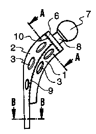
Method for producing a hollow shaft
endoprosthesis, in particular a hip joint prosthesis,
comprises the stages of producing two half-tubings,
which may be connected together to form the shape of
the shaft of the prosthesis, whereby they touch in
the region of two welding seams substantially running
in a longitudinal direction, by moulding or forging,
and welding together both moulded or forged
half-tubing in the region of the welding seams.

Revendications

Note : Les revendications sont présentées dans la langue officielle dans laquelle elles ont été soumises.


THE EMBODIMENTS OF THE INVENTION IN WHICH AN EXCLUSIVE
PROPERTY OR PRIVILEGE IS CLAIMED ARE DEFINED AS FOLLOWS:
1. A method for producing a hollow shaft of an endoprosthesis, in particular a
hip joint
prosthesis, including the following steps:
producing, by moulding or forging, two half-tubings, which are shaped to be
connected together to form the shape of the shaft of the prosthesis, whereby
said half-tubings
touch in the region of two welding seams substantially running in a
longitudinal direction,
and
welding together both said half tubings in the region of said welding seams.
2. The method as defined in claim 1, wherein the said half tubings consist of
a titanium-
aluminum-vanadium (TiAI6V4) wrought alloy.
3. The method as defined in claim 1, wherein said half tubings have a joint
end and an
end away from said joint end, and a continually diminishing thickness of the
said half-tubings
from the joint end to the end away from the joint end is refined and finished.
4. The method as defined in claim1, wherein said producing step includes
forming
openings in an outer side of said half-tubings.
5. The method as defined in claim 4, wherein said opening on the outer side of
said shaft
are covered over, a shaft opening far away from the joint end is plugged, the
hollow area of
said shaft is filled with polyethylene, the coverings and the plug are removed
and the surface
of the polyethylene is covered with apatite in the region of said openings.

6. The method as defined in claim 1, wherein said producing step includes
forming said
half tubings with convex outer surfaces, and recesses are formed in said
convex outer
surfaces of said half tubings and filled with Porocoat material.
7. The method as defined in claim 1, wherein said producing step includes said
half
tubings with concave inner surfaces, and recesses are formed in the concave
inner surfaces of
said half tubings.
8. The method as defined in claim 1, wherein said half tubings have a joint
end and an
end away from said joint end, and an attachment cone is welded onto the joint
end of said
hollow shaft.
9. The method as defined in claim 1, wherein said half-tubings have a joint
end and an
end away from said joint end, and an attachment cone is detachably connected
to the joint end
of said hollow shaft by means of a bracing ring with a predetermined breaking
point.
10. The method as defined in claim 1, wherein said half tubings are welded
together by
electron beam welding.
11. The method as defined in claim 8, wherein said welding seams between said
two half
tubings and said welding seam between said attachment cone and the joint end
of said hollow
shaft are planed by one of manual planing and a planing device.
12. The method as defined in claim 8, wherein said welding seams between said
two half
tubings are planed by one of said manual planing and a planing device.

13. The method as defined in claim 8, wherein said welding seam between said
attachment cone and the,joint end of said hollow shaft is planed.
14. The method as defined in claim 1, wherein said half-tubings have a joint
end and an
end away from said joint end, and a continually diminishing thickness of the
said half tubings
from the joint end to the end away from the joint end is produced by chemical
milling.
15. The method as defined in claim 1, wherein said producing step includes
forming
openings in an outer side of said half-tubings, and said openings are deburred
and planed.
16. The method as defined in claim 15, wherein said openings on the outer side
of said
shaft are covered over, a shaft opening far away from the joint end is
plugged, the hollow area
of said shaft is filled with polyethylene, the coverings and the plug are
removed and the
surface of the polyethylene is covered with apatite in the region of said
openings.
17. The method as defined in claim 14, wherein said producing step includes
forming said
half tubings with convex outer surfaces, and recesses are formed in the convex
outer surfaces
of said half-tubings and filled with Porocoat material.
18. The method as defined in claim 14, wherein said producing step includes
forming said
half tubings with concave inner surfaces, and recesses are formed in the
concave inner
surfaces of said half tubings.

19. The method as defined in claim 14, wherein said half-tubings have a joint
end and an
end away from said joint end, and an attachment cone is welded onto the joint
end of said
hollow shaft.
20. The method as defined in claim 14, wherein said half-tubings have a joint
end and an
end away from said joint end, and an attachment cone is detachably connected
to the joint end
by means of a bracing ring with a predetermined breaking point.

Description

Note : Les descriptions sont présentées dans la langue officielle dans laquelle elles ont été soumises.


20 0659 5
The present invention relates to a method for
producing a hollow shaft endoprosthesis, in
particular a hip .joi.nt prosthesis.
Hollow shaft endoprostheses have until now, usually
been cast-moulded ou.t: of metal alloys. This
processing method ca.n only be used for a certain
number of materials. 'The most widely used cast-
mouldable materials f:or making prostheses shafts are
a cobalt-chrome-molybdenum cast alloy and 316-cast
steel. A disadvanta.c~e is that these materials have a
low resistance to fatigue, so that fatigue fractures
can occur due to large bending stress fluctuations.
Other materials, s'uc'h as the chrome-nickel-
molybdenum-titan wrought alloy, the cobalt-chrome-
nickel-molybdenum-ti.t:an wrought alloy and the titan-
aluminium-vanadium wrought alloy were only used to
produce solid prostheses in the past. It is not
economical to produce :hollow shafts by machining a
solid bit.
1

2006595
It is an object of the invention to provide a method
for producing a hollow shaft endoprosthesis of the
above-mentioned type:, in which the shape of the
hollow shaft prost:he:sis can be easily modified, in
particular with regard to the shape and structure of
the inner and outer wa:l1 surface areas.
The above and other objects are accomplished
according to the inv-e:ntion by the provision of a
method comprising th.e following stages:
producing two half tubings, which may be connected
together to form the shape of i~he shaft of the
prosthesis, whereby they touch in the region of two
welding seams substantially running in a longitudinal
direction, by moulding or forging,
welding together both moulded or forged half-tubings
in the region of the welding seams.
The invention is based on the realization that the
preferred titan-aluminium-vanadium wrought alloy to
be used can be shaped :into any desired base parts by
known methods such a.s moulding or forging, and that
these base parts can. be connected together by
welding. A distinct advantage is the uncomplicated
and easy workability of the base parts prior to
welding, as this is f:ar easier than the finishing
work that has to be carried out on a moulded hollow
shaft or the utiliza.t:ion of a complicated mould-core.
2
.:~'..
3

2006595
It was found that the titan-aluminium-vanadium
wrought a_Lloy is a very good material for
constructing prostheses due to its good
biocompatability, high resistance to fatigue and good
corrosion-resistance. This material can be worked
economica:Lly by forging and mould and weld methods
since only simple parts are required and the
production time pe:r piece is low.
The base parts are semi-tubular in shape. These
semi-tubular parts a.re, if possible, already moulded
or forged with a dicrii.n:ishing thickness from the end
of the shaft near the joint to the end of the shaft
far away from the joint. The base part can be
finished, preferably by chemical abrasion, in order
to obtain a thickne~:s smaller than the minimum
achievable forging thickness .
The shaft wall can be intentionallv weakened in part.
in order to locally vary the bending and longitudinal
rigidity of the shaf:t:.
Openings in the wal7_s of the semi-tubular parts can
be inserted during mou7_ding or forging. Because of
the two-stage produc:t:ion process possible burrs can
be removed quickly and unproblematically prior to the
two parts being joined together.
3

20 oss9 5
Similarly, other deviations from a regular form, such
as, fox example, recesses :in the concave and convex
surfaces of the semi.--tubular parts, can at least be
preformed during mou7_ding or forging.
The two parts are connected together, as described in
a preferred embodiment of the .invention, by electron
beam welding. This welding method is characterized
by very narrow and uniform welding seams and is
therefore of a quali.t:y high enough to meet the set
requirements for prostheses shafts. In addition, the
areas on either side of the welding seam affected by
warmth radiation are much narrower than those areas
affected by WIG-welding (Wolfram inert gas).
Furthermore, electron beam welding requires less
finishing work to beg carried out on the welding seam.
If the connected hol.7_ow shaft has openings it can be
filled with polyethy7_ene. This measure is necessary,
as openings could lead to bone material growing into
the hollow area of the shaft and this is a hindrance
when having to, in some cases, remove the prosthesis.
The low rigidity of polyethylene does not greatly
influence the optimat:ed shape and material
characteristics of t:he hollow prosthesis. The
openings are coated with apatite in order to prevent
the bone from coming in direct contact with
polyethylene at the openings.
4
3

2006595
It is advantageous to fill the recesses with a Porocoat
material if these a:re on the convex outer surface of the
prosthesis shaft.
The neck. part of the preferred embodiment of the
prosthesis consist; of a cone attachment onto which ball
joints cf varying c~:iameters and cone lengths can be
attached.
In a broad aspect, then, the present invention relates
to a method for producing a hollow shaft of an
endoprosthesis, in particular a hip joint prosthesis,
including the following steps: producing, by moulding or
forging, two half-tubings, which is shaped to be
connected together t=o form the shape of the shaft of the
prosthesis, whereb~T said half-tubings touch in the
region of two welding seams substantially running in a
longitudinal direct:_~on, and welding together both said
half-tubings in t:~e region of said welding seams.
?0
BRIEF DESCRIPTION OF THE DRAWINGS
Figure 1 is a perspective view of two moulded or forged
half-tubing which ri~ave been produced using the method
according to the :invention.
Figure 2 is a side elevation of a welded hollow shaft
produced according t:o the invention.
Figure 3 is a sectional view A-A of the welded hollow
30 shaft according to Figure 2.
;SECTION 8 COflRECTION
SEE CERTIFICATE
CORRECTION - ARTICLE 8
VOIfl CERTIFICA~
sJ 5

2006595
S
1S
2S
Figure 4 is a sectional view B-B of the welded hol7_ow
shaft according to h'igure 2.
Figure 5 is a partially sectional elevational view of a
hollow shaft prosthesis with a detachable head part.
SECTION B CORRECTION
SEE CERTIFICATE
COflRECTION - ,~I~TICI E H
VOIR C~RTtFtCAT
5 (a)
3S

20 065 9 ~
In the first stage of: the production method two
differing half-tub:in.g .L and 2, as illustrated in
Figure 1, are moulded or forged. The half-tubing 1
and 2 are shaped to fit together. The preferred
material to be used i.s a titan--aluminium-vanadium
wrought a:Lloy. This material <~annot be cast-moulded
but possesses many characteristics favourable for
arthroplastics.
The two half-tubings: 1 and 2 are shaped in such a way
that they can be connected together to form a curved
tube with a continua.l_ly increasing diameter and a
continually increasing wall thickness in one same
direction. The continual variation of the wall
thickness in the a:xi.al direction of the shaft and the
insertion of certain openings 3 or recesses 4 in the
inner surface of both half-tubings have already been
produced during moulding or forging. Such
constructive detail Enables the stress distribution
in the prosthesis to approximately vary according to
the physiological rigidity and the bending properties
of the surrounding bone.
The half-tubi.ngs 1 and 2 are the medial, outward
curving part (half-tubing 1) and the lateral, inward
curving part (half-tubing 2) of the hollow shaft.
This division is technologically advantageous since
the outward curving part is shorter than the inward
curving part at the end of the shaft far away from
the joint. (Here the simultaneously filed patent
application of the ;game inventor is referred to.)
6

20 0659 5
Both semi-tubing~~ l and 2 are deburred and planed after
forging and mouldi:Zg and, if required, after the
insertion of openings and/or recesses. A possible
finishing, by chemical milling or any other cutting
method, to better l~.:he continual decreasing wall
thickne~;s of the inside or on. the outside is
unproblematic in this "cut-open" state.
As shown. in FIG. 2, semi-tubings 1 and 2 can be welded
together, as shown by welding seam 9. Also, a joint
part 6 can be welded at a joint end, as shown by welding
seam 10. High qua=L:ity welding, such as electron beam
welding can be used.
Recesses in the out=er wall surface of the hollow shaft 5
are filled up with l?orocoat material, since it is easier
to break away bone material from the surface than it is
to break away a bone=_ spar from the inside of the
prosthesis.
A further variation,, by which the explanation of a
prosthesis is made possible, is illustrated in FIG. 5.
A joint part 6 can include a joint, such as an element 7
disposed on a connecting member 8. The joint part 6 is
not welded to the hollow shaft but is detachably flanged
to it. This can preferably be done with a bracing ring
11 with a predetermined breaking point. The inside of
the hollow shaft i~~ therefore easily accessible after
breaking off the joint part 6. The surgeon can then
remove any of the bone that may have grown into the
hollow area of the :haft, using a burr or a drilling
machine, without damaging the cortical.
SECTION 8 CORRECTION
~5 ~ ~ SEE CERTIFICATE
COR~iECTION - ARTICLE 9
VOIR C~RTiFICAF

2006595
It will be understood that the above description of
the present invent_Lon. is susceptible to various
modifications, changes and adaptatians, and the same
are intended t=o be comprehended within the meaning
and range of equivalents of the appended claims.
8

Dessin représentatif
Une figure unique qui représente un dessin illustrant l'invention.
États administratifs

2024-08-01 : Dans le cadre de la transition vers les Brevets de nouvelle génération (BNG), la base de données sur les brevets canadiens (BDBC) contient désormais un Historique d'événement plus détaillé, qui reproduit le Journal des événements de notre nouvelle solution interne.

Veuillez noter que les événements débutant par « Inactive : » se réfèrent à des événements qui ne sont plus utilisés dans notre nouvelle solution interne.

Pour une meilleure compréhension de l'état de la demande ou brevet qui figure sur cette page, la rubrique Mise en garde , et les descriptions de Brevet , Historique d'événement , Taxes périodiques et Historique des paiements devraient être consultées.

Historique d'événement

Description Date
Inactive : Périmé (brevet - nouvelle loi) 2009-12-22
Inactive : CIB de MCD 2006-03-11
Inactive : Page couverture publiée 2001-06-11
Inactive : Acc. récept. de corrections art.8 Loi 2001-06-11
Inactive : Correction - Doc. d'antériorité 2001-06-11
Accordé par délivrance 2001-05-08
Inactive : Page couverture publiée 2001-05-07
Préoctroi 2001-02-14
Inactive : Taxe finale reçue 2001-02-14
Un avis d'acceptation est envoyé 2000-08-30
Lettre envoyée 2000-08-30
Inactive : Supprimer l'abandon 2000-08-25
Inactive : Lettre officielle 2000-08-25
Inactive : Demande ad hoc documentée 2000-08-25
Inactive : Renseign. sur l'état - Complets dès date d'ent. journ. 2000-07-18
Inactive : Dem. traitée sur TS dès date d'ent. journal 2000-07-18
Inactive : Abandon. - Aucune rép. à lettre officielle 2000-07-11
Inactive : Pages reçues à l'acceptation 2000-07-10
Inactive : Lettre officielle 2000-04-11
Inactive : Approuvée aux fins d'acceptation (AFA) 2000-04-06
Toutes les exigences pour l'examen - jugée conforme 1996-09-17
Exigences pour une requête d'examen - jugée conforme 1996-09-17
Demande publiée (accessible au public) 1990-06-23

Historique d'abandonnement

Il n'y a pas d'historique d'abandonnement

Taxes périodiques

Le dernier paiement a été reçu le 2001-04-09

Avis : Si le paiement en totalité n'a pas été reçu au plus tard à la date indiquée, une taxe supplémentaire peut être imposée, soit une des taxes suivantes :

  • taxe de rétablissement ;
  • taxe pour paiement en souffrance ; ou
  • taxe additionnelle pour le renversement d'une péremption réputée.

Les taxes sur les brevets sont ajustées au 1er janvier de chaque année. Les montants ci-dessus sont les montants actuels s'ils sont reçus au plus tard le 31 décembre de l'année en cours.
Veuillez vous référer à la page web des taxes sur les brevets de l'OPIC pour voir tous les montants actuels des taxes.

Historique des taxes

Type de taxes Anniversaire Échéance Date payée
TM (demande, 9e anniv.) - générale 09 1998-12-22 1998-04-20
TM (demande, 10e anniv.) - générale 10 1999-12-22 1999-04-16
TM (demande, 11e anniv.) - générale 11 2000-12-22 2000-04-14
Taxe finale - générale 2001-02-14
TM (demande, 12e anniv.) - générale 12 2001-12-24 2001-04-09
TM (brevet, 13e anniv.) - générale 2002-12-23 2002-11-19
TM (brevet, 14e anniv.) - générale 2003-12-22 2003-11-17
TM (brevet, 15e anniv.) - générale 2004-12-22 2004-11-08
TM (brevet, 16e anniv.) - générale 2005-12-22 2005-11-08
TM (brevet, 17e anniv.) - générale 2006-12-22 2006-11-08
TM (brevet, 18e anniv.) - générale 2007-12-24 2007-11-09
TM (brevet, 19e anniv.) - générale 2008-12-22 2008-11-10
Titulaires au dossier

Les titulaires actuels et antérieures au dossier sont affichés en ordre alphabétique.

Titulaires actuels au dossier
JOHNSON & JOHNSON
Titulaires antérieures au dossier
CURT KRANZ
Les propriétaires antérieurs qui ne figurent pas dans la liste des « Propriétaires au dossier » apparaîtront dans d'autres documents au dossier.
Documents

Pour visionner les fichiers sélectionnés, entrer le code reCAPTCHA :


Pour visualiser une image, cliquer sur un lien dans la colonne description du document (Temporairement non-disponible). Pour télécharger l'image (les images), cliquer l'une ou plusieurs cases à cocher dans la première colonne et ensuite cliquer sur le bouton "Télécharger sélection en format PDF (archive Zip)" ou le bouton "Télécharger sélection (en un fichier PDF fusionné)".

Liste des documents de brevet publiés et non publiés sur la BDBC .

Si vous avez des difficultés à accéder au contenu, veuillez communiquer avec le Centre de services à la clientèle au 1-866-997-1936, ou envoyer un courriel au Centre de service à la clientèle de l'OPIC.

({010=Tous les documents, 020=Au moment du dépôt, 030=Au moment de la mise à la disponibilité du public, 040=À la délivrance, 050=Examen, 060=Correspondance reçue, 070=Divers, 080=Correspondance envoyée, 090=Paiement})


Description du
Document 
Date
(aaaa-mm-jj) 
Nombre de pages   Taille de l'image (Ko) 
Dessins 2000-07-09 1 17
Abrégé 2000-07-09 1 17
Dessin représentatif 2001-04-22 1 5
Description 2001-06-10 9 268
Revendications 2001-06-10 4 122
Dessin représentatif 1998-07-30 1 4
Description 2000-07-09 9 261
Revendications 2000-07-09 4 115
Avis du commissaire - Demande jugée acceptable 2000-08-29 1 163
Correspondance 2000-04-10 1 13
Correspondance 2000-07-09 11 291
Correspondance 2001-02-13 1 39
Taxes 2000-04-13 1 34
Taxes 2001-04-08 1 37
Taxes 1998-04-19 1 45
Taxes 1999-04-15 1 39
Taxes 1997-04-06 1 38
Taxes 1996-04-15 1 37
Taxes 1995-10-15 1 37
Taxes 1994-12-21 1 37
Taxes 1993-12-14 1 33
Taxes 1992-11-26 1 28
Taxes 1991-11-20 1 26
Correspondance de la poursuite 1996-09-16 1 33
Correspondance de la poursuite 1999-07-27 3 81
Correspondance de la poursuite 2000-02-22 2 57
Correspondance de la poursuite 1999-01-24 2 46
Courtoisie - Lettre du bureau 1996-10-06 1 46
Demande de l'examinateur 2000-04-10 1 30
Courtoisie - Lettre du bureau 2001-06-10 1 23
Demande de l'examinateur 1999-08-22 2 47
Demande de l'examinateur 1999-02-10 2 71
Demande de l'examinateur 1998-07-27 2 60