Note : Les descriptions sont présentées dans la langue officielle dans laquelle elles ont été soumises.
~QOE~~~~
1
Sound insulated interchanaeable lens
The present invention relates to an interchangeable lens
suitable for use in conjunction with a motion picture camera,
said lens having a lens mount that can be removably attached
to said camera, a lens casing connecting to said lens mount
and an external casing both housing adjusting elements of said
interchangeable lens and being connected through sound-
absorbing buffer rings to said lens casing. The invention
also relates to a method suitable for the production of such
interchangeable lens.
In film production, the noise produced by the running
camera inevitably becomes a disturbing "background noise".
Effective noise reduction in movie camera technology is
conventionally obtained by fitting the lens assembly with a
detachable anti-noise cover. This method of sound
insulation, however, hampers both operation of the camera and
manipulation of the lens.
In order to improve sound insulation without interfering
with the manipulation of the camera lens, EP-A-87 890 090.1
discloses an interchangeable lens whose external casing is
sound-insulated relative to the lens casing. Such insulation
is accomplished by rigidly connecting the shell constituting
the major portion of the external casing by means of a buffer
ring to the flange of the interchangeable lens, which in turn
can be coupled by means of a bayonet ring to the camera
housing. This arrangement substantially attenuates
propagation of sound waves from the camera housing to the
external casing.
Effective object-side sound insulation can also be
obtained by fitting a flat sheet of glass in front of the lens
casing at the object-side end zone of the external casing.
The glass sheet, surrounded by a buffer ring, is held in place
inside a reflex guard which, being attached to the lens
casing, features for the purpose of sound insulation a further
buffer ring on the circumferential zone adjoining the external
mount.
zsoss2~
2
An object of the present invention is thus the improvement
of an interchangeable lens of the above-mentioned type with a
view to improving sound insulation while ensuring simplicity
of design and low production cost.
According to one aspect of the invention there is provided
an interchangeable lens suitable for use in conjunction with a
motion picture camera, said lens having a lens mount that can
be removably attached to said camera, a lens casing connecting
to said lens mount and an external casing both housing
adjusting elements of said interchangeable lens and being
connected through sound-absorbing buffer rings to said lens
casing, whereby a buffer ring located on the object side of
said interchangeable lens and a buffer ring located on the
camera side of said interchangeable lens serve to radially
support and centre said external casing at end zones thereof
on said lens casing.
The proposed design for the interchangeable lens admits a
simple method of completely insulating the external casing
from the lens easing. Rigid securing of the buffer rings at
two points obviates rigid attachment of the external casing to
the lens flange and eliminates the potential for sound bridge
development between lens flange and casing that could be
abetted by the radial protection required by the buffer ring
arrangement enunciated in the prior art patent application.
Furthermore, the method presently proposed for providing
buffer rings around the lens casing allows efficient mounting
of the external casing whereby the latter is axially slid over
the lens casing from the camera side.
The object-side buffer ring axially secures the external
casing on top of the lens casing, thus eliminating the need
for special attachment of the external casing to the lens
casing.
Connecting pins protruding from the lens casing both
prevent development of sound bridges between the lens and the
external casing of the interchangeable lens and serve to
connect, by means of buffering elements, the adjusting
elements located in the external casing, i.e. a focus ring, a
2Q~D~E~62~
3
range setting ring and an aperture ring, to corresponding
adjusting mechanisms located inside the lens casing.
An alternate version of the proposed system relates to the
design of the frontal zone of the lens casing. A forward lens
system is borne and centrEd inside the lens casing by means of
a sound-absorbing buffer ring. The use of a frontal lens
system designed to enhance specific optical qualities in the
interchangeable lens eliminates additional components needed
to effectively insulate the lens casing on the object-side.
Besides absorbing sound waves that are produced by the
camera mechanism and that exit frontally from the lens, the
proposed forward lens system, by virtue of its arrangement
inside a supportive and sound-absorbing buffer ring that also
centers such forward lens system, permits effective insulation
against structure-propagated sound waves. This arrangement
removes the need for the installation, in the forward zone of
the interchangeable lens, of bearing elements liable to
conduct sound waves.
The precision with which the forward lens system is
radially borne inside the buffer ring ensures exact
positioning of the forward lens system along the longitudinal
axis of the lens.
In a particularly advantageous embodiment of the present
invention, the barrel forms, together with the lens mount of
the forward lens system, a unit of production, thus permitting
the buffer ring, which centers the interchangeable lens during
installation, to be vulcanized into a precisely defined
intermediate cavity located between the barrel and the lens
mount of the forward lens system, without affecting the
centering of the lens mount in relation to the barrel.
The method proposed for producing an interchangeable lens
of the kind first mentioned comprises that a barrel connecting
to the lens casing and serving to house the forward element,
which is embodied as a forward lens system, is manufactured in
one integral unit together with a lens mount of the forward
lens system. A buffer ring is then vulcanized into a cavity
especially provided in such production unit, whereafter the
i~~~~6i~~~
4
latter is separated into two individually-treated parts, which
is to say, the barrel and the lens mount, whereby the buffer
ring remains, following the separation procedure, attached to
the screw-in barrel and the lens mount.
After the production unit is separated into barrel and
lens mount, which takes place after the buffer ring has been
vulcanized into position, the bore of the lens mount remains
centred in relation to the bearing surface of the barrel,
despite the presence of the buffer ring which has been
vulcanized into place.
Vulcanization of the buffer ring inside the single-piece,
annular production unit ensures that the buffer ring, even
following separation of barrel and lens mount, will not affect
the bearing tolerance existing between the bore of the lens
mount and the bearing surface of the screw-in barrel. The
original centred position, therefore, remains unchanged.
Both the object-side buffer ring, which bears the external
casing and the buffer ring surrounding the forward lens system
are supported upon opposing support surfaces of the barrel,
which is screwed together with the lens casing. The advantage
of the mutual support system of external casing, barrel and
forward lens system, viewed in cross section, is that of
preventing bearing forces acting in different planes from
locally deforming the lens casing.
In another advantageous embodiment of the present
invention, the special disposition of a reflex guard between
an object-side end zone of the external casing and the forward
lens system permits the existence of an annular air space
between the forward lens system and the reflex guard, an
arrangement that ensures that the coaxial alignment, by radial
bearing inside the buffer ring, of the forward lens system
relative to the longitudinal axis of the lens, will not be
impaired should the forward lens system come into contact with
the reflex guard.
A further advantageous feature of the present invention
provides for axial positioning by the reflex guard of the
object-side buffer ring inside the external casing. The
CA 02006624 1999-06-08
object-side buffer ring, being vulcanized to the inner surface
of a casing, fixes in place the external casing relative to
the lens casing.
In accordance with one aspect of the present invention
5 there is provided an interchangeable lens that can be
removably mounted to a motion picture camera housing,
comprising mount structure for removable attachment to said
camera housing, external casing structure, said external
casing structure comprising adjusting elements of said
interchangeable lens, lens casing structure connecting said
mount structure and said external casing structure; a first
sound-absorbing buffer ring structure located on an object
side of said interchangeable lens and connecting said external
casing structure to said lens casing structure; a second
sound-absorbing buffer ring structure located on a camera side
of said interchangeable lens, said first and second buffer
ring structures serving to radially support and center said
external casing structure at end zones thereof on said lens
casing structure; and a third sound-absorbing buffer ring
structure, and a forward lens system in a forward zone of said
lens casing structure and connected to said lens casing
structure, said forward lens system being both centrally borne
in relation to said lens casing structure and being connected
to said external casing structure by means of said third
sound-absorbing buffer ring structure.
In accordance with another aspect of the present
invention there is provided a method of producing an
interchangeable lens wherein a forward lens system lens mount
is initially manufactured as a unitary portion of a lens
casing structure with a cavity between a lens mount and a
barrel portion, and including a step of separating said
forward lens system lens mount from said lens casing structure
following vulcanization of a first sound-absorbing buffer ring
structure in said cavity so that said first buffer ring
structure remains connected following said separation step to
both said barrel portion and said forward lens system lens
mount.
CA 02006624 1999-06-08
5a
In accordance with yet another aspect of the present
invention there is provided a method of producing an
interchangeable lens wherein a forward lens system lens mount
is initially manufactured as a unitary portion of said lens
casing structure, and including a step of separating said
forward lens system lens mount from said lens casing structure
following securing of a first and third sound-absorbing buffer
ring structures to a barrel portion so that a first buffer
ring structure remains connected, following said separation
step to both said barrel portion and said forward lens system
lens mount.
The present invention is described in greater detail in
the following with reference to the accompanying drawings, in
which:
Fig. 1 is a longitudinal section through an interchangeable
lens, along the axis of such lens; and
Fig. 2 is a longitudinal section through an unfinished
mounting element for the forward lens system.
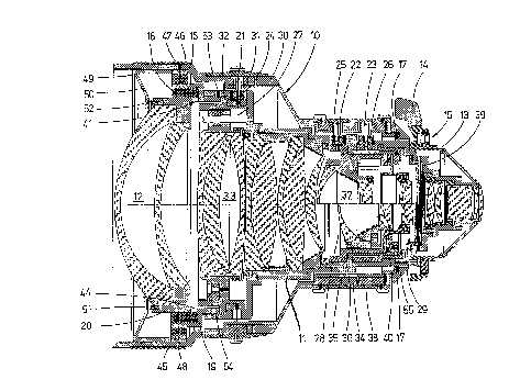
Figure 1 shows a sound-insulated interchangeable lens
comprising essentially an external casing 10, a lens casing 11
and a forward lens system 12. The interchangeable lens is,
for the purpose of attachment to a schematically-drawn motion
picture camera, provided with a lens mount 13 attaching
directly to lens casing 11, and is capable of being inserted
into a camera bayonet 15 that can be locked with the aid of a
locking lever 14.
External casing 10 is radially supported, through buffer
rings 16, 17, on top of lens casing 11. Buffer rings 16 and
17 are thus able to act at the same time as centering
elements. Object-side buffer ring 16 also axially secures
external casing 10 in relation to lens casing 11.
Lens system 12, which fits inside lens casing 11, is
radially borne by a further buffer ring 18 arranged between a
screw-in barrel 19, which forms an extension of lens casing 11
on the object side, and a lens mount 20 of forward lens system
12. The manner in which the latter fits into buffer ring 18
CA 02006624 1999-06-08
5b
precludes structural contact between screw-in barrel 19 and
lens mount 20.
The proposed arrangement of forward lens system 12 inside
lens casing 11 prevents sound waves, which are conducted from
the mechanism of motion picture camera to lens casing 11, from
exiting through forward lens system 12 toward the object. The
insulation by means of buffer rings 16, 17, of external casing
from lens casing 11 serves to radially protect lens casing
11 from the environment.
CA 02006624 1999-06-08
6
Catch pins 21, 22, 23, which extend from lens casing
11 into external casing 10 and permit the control of
adjustment mechanisms located inside lens casing 11, are
prevented from becoming sound bridges between lens casing 11
and external casing 10 by being borne, in the zone of lens
casing 11, inside buffer elements 24, 25, 26.
The adjustment mechanisms comprise, more particularly, a
focus regulator 27, a depth of field setter 28 and an aperture
setter 29. Catch pin 21 serves to mechanically couple to
focus regulator 27 a focus ring 31 that can be rotated about a
fine-adjustment ring 30 that is attached to external casing
10. Focus ring 31 permits selection from a range of focal
depths obtainable with the interchangeable lens, which is
embodied as a zoom lens for the purposes of the present
embodiment.
In this embodiment, focus regulator 27 comprises
essentially a zoom lens system 33 that can be slid, with the
aid of an adjustment ring 32, along the longitudinal axis of
the interchangeable lens. In order to be able to adjust the
interchangeable lens to the proper focal depth, a distance
ring 35, which can be rotated relative to external casing l0
and a fine-adjustment ring 34, regulates, by means of catch
pin 22, the position of focusing lens system 37, which can be
slid by means of an adjustment ring 36 along the longitudinal
axis of the interchangeable lens.
Catch pin 23, finally, serves to connect an aperture ring
38, which can be rotated relative to external casing 10, to a
carrier casing 40 that regulates an aperture mechanism 39.
Forward lens system 12 connects by means of screw-in
barrel 19 to lens casing 11. Buffer ring 18, which radially
encloses lens mount 20 of forward lens system 12, serves to
sound-insulate forward lens system 12 from screw-in barrel 19.
The latter, together with buffer ring 18 and lens mount 20
form an integral unit, since buffer ring 18 is annularly
vulcanized into position between screw-in barrel 19 and lens
mount 20.
In order to maintain the sound-insulating function of
7
buffer ring 18, an annular axial gap 41 is provided between
lens mount 20 and screw-in barrel 19 and so prevents lens
mount 20 from coming into direct contact with screw-in barrel
19.
Because centering of forward lens system 12 in relation to
the overall optical system of the interchangeable lens is
highly important, this function must be taken into
consideration during manufacture of the unit comprising screw-
in barrel 19, buffer ring 18 and lens mount 20. For this
reason, a special process is used to assemble the unit.
Produced first is a single-piece production unit 42
comprising screw-in barrel 19 and lens mount 20 and embodied
as an unfinished piece as illustrated in Figure 2. Next,
buffer ring 18 is annularly vulcanized into an intermediate
annular space 43 of production unit 42. Following the
vulcanizing step, production unit 42 is finished by lathing.
In the final production step following lathing, removal of
the piece of material 44 remaining between lens mount 20 and
screw-in barrel 19 produces gap 41, which prevents direct
contact between lens mount 20 and screw-in barrel 19. Piece
of material 44, which is removed before forward lens system 12
is mounted, is indicated in Figure 1 by a broken line.
Buffer ring 16 is fitted over the circumference of screw-
in barrel 19 in order both to center external casing 10 and to
axially position external casing 10 in relation to lens casing
il. Buffer ring 16 is, to this end, vulcanized to the inner
surface of a casing 45, which sits axially against a shoulder
46 of external casing 10. Threaded pins 47, 48 serve to
maintain casing 45 in this position.
At the object side of the lens assembly, a reflex guard 49
is screwed into external casing 10 to stop against casing 45.
Reflex guard 49 extends obliquely with its protective wall 50
from external casing 10 to forward lens system 12 and permits
the existence of an annular, axial air gap 52 between
protective wall 50 and a forward threaded ring 51 of forward
lens system 12. Reflex guard 49 is thus prevented from
interfering with the centering by buffer ring 18 of forward
2~U~6~;~'~
s
lens system 12.
This embodiment of the interchangeable lens permits very
simple mounting of three components (external casing 10, lens
casing 11 and forward lens system 12) which are separated by
buffer rings 16, 17, 18.
Beginning at lens casing 11, forward lens system 12 is
screwed together with screw-in barrel 19 into lens casing 11
where it is held in position by threaded pins 53, 54. Next,
external casing 10 is slid away from the camera body along
lens casing 11 until bore shoulder 46 comes to rest against
casing 45 of buffer ring 16, which has already been fitted
over the circumference of screw-in barrel 19.
After connecting pins 21, 22 23 have been screwed into
buffer elements 24, 25 26 of lens casing 11, the auxiliary
components of external casing 10, such as focus ring 31, fine-
adjustment ring 30, distance ring 35, and fine-adjustment ring
34, can be installed. A support ring 55 is then screwed
together with a buffer ring 17 located inside such support
ring 55 in order to support external casing 10 in the zone
adjoining the camera. The installation of aperture ring 38
completes the assembly of external casing 10. Finally, reflex
guard 49 is screwed, at the object side, into external casing
10.
The scope of application of the proposed system is not
restricted to the embodiment example described. Rather, a
number of alternate versions can be contemplated, which,
despite.having fundamentally different designs, are able to
employ the proposed solution.