Note : Les descriptions sont présentées dans la langue officielle dans laquelle elles ont été soumises.
ROTARY-TILTABLE CAR WA~H 8Y8TEM
:W
6 ~ ~?
BACKGROUND OF THE INVENTION
Field of the Invention
The present invention relates generally to
automatic vehicle wash systems and more particularly
to a reciprocating gantry-type wash system designed
to efficiently wash the front and rear of the
vehicle as well as the sides thereof.
Backqround of the Invention
There are many types of vehicle wash system
adapted to readily clean a vehicle without the need
of hand scrubbing. One basic form of wash system is
merely to use a wand through which high-pressure
water is emitted against the side of the vehicle
with the wand normally being manipulated by an
individual washing his or her own vehicle. More
automated systems utilize the same concept of
emitting jet sprays of water against the side of a
vehicle but through use of an array of such nozzles
disposed along both sides and across the top of tl.e
vehicle. Such arrays are sometimes adapted to move
in a loop around the vehicle with thé vehicle
remaining in place while others move relative to the
vehicle in a straight line along the length of the
vehicle. In either event, the object is to expose
the entire exterior surface of the vehicle to the
jet sprays of water to remove dirt, scum and other
road debris from the surface of the vehicle.
More elaborate vehicle wash systems which are
generally more efficient in cleaning the exterior
surface of the vehicle have been referred to as
tunnel-type car wash systems wherein a vehicle is
advanced through a series of stages spaced along a
linear path with different operations occurring at
A
~.,
2006639
_ 2
the various stages as the vehicle is advanced
through the tunnel. The various stages would
include pre-soaking, rinsing, scrubbing, waxing, and
other similar operations. Generally, in a tunnel-
type wash system, a fabric curtain, commonlyreferred to as a mitter curtain, defines one of the
washing stages with the mitter curtain being
comprised of a plurality of strips of felt or other
similar material which are rocked back and forth
along the path of movement of the vehicle so that as
the vehicle is moved thereby, the felt strips will
abrasively scrub and remove dirt and other debris
from the surface of the vehicle. While this
scrubbing action normally takes place in combination
with a soapy water to minimize scratching the paint
on the vehicle, it has been determined that repeated
usage of such a cleaning system has a detrimental
effect on the paint in that minor scratches are
imparted to the surface, either by the felt fabric
itself or by the granular dirt particles that the
curtain removes from the surface of the vehicle.
As a result of the detrimental abrasion of a
mitter curtain on the paint of a vehicle, many
vehicle owners prefer not to use tunnel-type wash
systems and would rather prefer to use a system
wherein water is merely directed at the surface of
the vehicle in a high-pressure stream to remove dirt
and other material from the surface thereof. Of
these type~ of wash systems, the most common is what
may be referred to as a reciprocating gantry-type
system wherein a framework carrying spray nozzles
disposed along an inverted U-shaped frame is moved
reciprocally over the car to spray cleaning fluid
thereon. It will be appreciated, however, that with
such systems it is difficult to wash the front and
rear of the vehicle as the nozzles through which the
cleaning fluid is dispensed are usually directed
2006639
,~ 3
perpendicularly to the line of movement of the
apparatus and therefore are not directed at the
front and rear of the vehicle.
While some systems have been devised for moving
the sprays along a curved track in front and behind
the vehicle, such systems are less than desirable in
that they are normally mechanically more complex and
require that the system be suspended from an
overhead location rather than supported on the same
surface as is the vehicle.
It is accordingly an object of the present
invention to provide a car wash system of the type
wherein a gantry-like apparatus is reciprocated over
the vehicle but including a system for thoroughly
cleaning the front and rear of the vehicle as well
as the top and sides.
SUMMARY OF THE INVENTION
The vehicle wash apparatus of the present
invention is of the reciprocating gantry type
wherein an inverted U-shaped frame is mounted on
longitt1~n~lly extending rails for reciprocating
movement over a vehicle situated between the rails.
The apparatus includes manifolds with high-pressure
nozzles for dispensing cleaning fluids directly onto
the vehicle. The dispensing manifolds are moùnted
so as to be tiltable relative to the vehicle whereby
the angle at which the cleaning fluid is directed at
the vehicle can be modified at the front and rear of
the vehicle to direct the spray at these surfaces.
In the preferred form of the invention, the
dispensing manifolds are rotated while directing
cleaning fluid at the vehicle, and the entire
rotating manifold is tilted when the apparatus
approaches the front and rear of the vehicle to
direct the cleaning fluid at the front and rear
surfaces.
2006639
.,,,_
It will be appreciated that the apparatus of
the present invention is described as being
reciprocally mounted for movement relative to a
vehicle being washed, but the principle features of
the apparatus could be employed in a stationary
apparatus wherein the vehicle was moved through the
apparatus.
A unique bearing seal is utilized to support
the rotating manifolds in a manner such that the
high-pressure cleaning fluids can be directed
through the bearing seal in a leak-proof manner.
Other aspects, features and details of the
present invention can be more completely understood
by reference to the following detailed description
of a preferred embodiment, taken in conjunction with
the drawings, and from the appended claims.
BRIEF DF~CRIPTION OF THE DRAWINGS
Fig. 1 is a perspective view of the apparatus
of the present invention with a vehicle being shown
in a position to be cleaned by the apparatus.
Fig. 2 is a front elevation of the apparatus
shown in Fig. 1 with the vehicle shown in phantom
lines.
Fig. 3 is a vertical section taken along
line 3-3 of Fig. 2.
Fig. 4 is a vertical section taken along
line 4-4 of Fig. 2.
Fig. 5 is a section taken along line 5-5 of
Fig. 4.
Fig. 6 is a section taken along line 6-6 of
Fig. 5.
Fig. 7 is a section taken along line 7-7 of
Fig. 4.
Fig. 8 is a view of the upper portion of the
apparatus as seen in Fig. 4 with the tiltable arms
being shown in a centered position.
2006639
Fig. 9 is a section taken along line 9-9 of
Fig. 2.
Fig. 10 is an operational view of the apparatus
of the present invention shown in three different
positions relative to a vehicle being cleaned
thereby.
Fig. 11 is an operational plan view similar to
Fig. 10 showing the apparatus in three different
positions relative to a vehicle being cleaned
thereby.
Fig. 12 is a perspective view of one of the
lower rotating dispensing manifolds connected to a
power source and li~uid supply through the bearing
seal of the present invention.
Fig. 13 is a perspective view of the bearing
seal of the present invention.
Fig. 14 is a section taken along line 14-14 of
Fig. 13.
Fig. 15 is an exploded perspective view of the
bearing seal of the present invention illustrating
the various component parts thereof.
DESCRIPTION OF THE PREFERRED EMBODIMENT
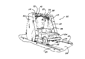
Referring first to Fig. 1, the wash
apparatus 20 of the present invention can be seen to
be of the gantry-type and includes a framework 22
adapted to be reciprocally driven along a pair of a
parallel rails 24 mounted on the floor 26 of a
vehicle wash location. The parallel rails are
cylindrical in configuration and define a driveway
therebetween in which a vehicle can enter the
apparatus, be temporarily stationed while being
washed, and exit the apparatus by proceeding
forwardly therefrom.
The apparatus of the invention includes an
upstanding inverted U-shaped housing 28 forming a
part of the framework 22 on which the working
Z00663g
~_ 6
-~ components of the apparatus are mounted. Thehousing includes a number of planar sheets 30 of
suitable rigid material which are mounted upon
horizontal and vertical frame members 32 disposed
interiorly thereof. The housing sheets define an
enclosure on opposite sides and across the top of
the apparatus for working components of the
apparatus.
The apparatus 20 further includes a pair of
vertically disposed rotating manifolds 34 positioned
adjacent the lower ends of the sides of the housing
and a pair of generally horizontally disposed
rotating manifolds 36 mounted on frame members 38
that define an upper generally horizontal bridge
between the sides of the housing. The upper
rotating manifolds 36 can be seen to be disposed so
as to direct washing fluid at the vehicle in a
slightly downwardly convergent manner so that the
fluids impinge the top of the vehicle as well as the
sides thereof. The vertically oriented lower
rotating manifolds 34 are disposed to direct washing
fluids directly at the sides of the vehicle. As
will be appreciated from the description that
follows, both the vertical and horizontal rotating
manifolds are mounted on tiltable mechanisms so that
the angle at which the washing fluid is dispensed at
the vehicle can be varied depending upon the
relative position of the vehicle and the apparatus
as seen in Figs. 9 and 10.
With particular reference to Fig. 4, it can be
seen that the framework 22 of the apparatus is
mounted on two pair of wheels 40d and 40i with one
pair being associated with each side of the
apparatus. The wheels are rotatably mounted at the
bottom of the associated side of the framework with
one wheel 40i on each side being merely an idler
wheel while the opposite wheel 40d is driven by a
Z00663~
belt 42 connection to a drive motor 44. The wheels
are mounted on suitable axles 46 and bearings 48 so
that the housing and framework can be reciprocally
moved along the rails 24 in a smooth and efficient
manner. A gear-reduction box 50 is operably
connected to the drive motor 44 to impart a desired
rotational speed to the driven wheel 4Od. Drive
motors 44 are provided on each side of the apparatus
so that the apparatus can be retained in a
perpendicular relationship with the guide rails
thereby not placing the apparatus in a bind as it is
moved along the rails.
As best seen in Fig. 4, one of the lower
vertically oriented rotating manifolds 34 is
positioned on each side of the housing 20 at a
location immediately above the drive motor 44. The
vertically oriented rotating manifolds are operably
connected to an electric motor 52 and gear box 54
through a flexible coupling 56 and a unique bearing
seal element 58 as illustrated in Fig. 11. The
electric motor 52 and gear box 54 are anchored to a
yoke-shaped frame member 60 for pivotal movement in
a manner to be described hereinafter. A box-like
cover 62 for the bearing seal element 58 is provided
for anchoring a fluid supply line 64 from a source
of fluid to the bearing seal also in a manner to be
described in detail hereinafter. It will therefore
be appreciated that the electric motor 52 associated
with each lower manifold 34 is adapted to
selectively rotate the manifold while fluid is being
delivered to the interior of the manifold and a
plurality of jet nozzles 66 are spaced along the
length of the manifold for emitting the fluids at a
high pressure against the surface of a vehicle.
With reference to Figs. 1, 2, 4 and 8, it can
be seen that the upper generally horizontal rotating
manifolds 36 are supported on and between associated
Z006639
'"....
pairs of the support frame members 38 which extend
parallel to each other and in spaced relationship so
as to be connected at a centered location by a plate
bracket 68 allowing a very flat inverted V-shaped
orientation of the upper support frame members 38.
Each upper generally horizontal rotating manifold 36
is operably connected to a motor 70, gear box 72,
flexible coupling 74, and bearing seal element 58
similarly to the vertically rotating manifolds 34,
lo but the upper manifolds are, as mentioned
previously, mounted on an associated pair of support
frame members 38. The frame members 38 are hollow
in construction and adapted to conduct cleaning
fluid supplied thereto through a supply hose 76 to
the bearing seal elements 58. Additional supply
hoses 77 transfer the cleaning fluid from the frame
members 38 to the bearing seal elements from
locations close to the bearing seal elements.
The outermost ends of the parallel frame
members 38 are supported on the upper ends of
tiltable or pivot arms 78 which are operably
connected to a pivot shaft 80 and bearings 82 as
probably seen best in Figs. 4 and 8. The
bearings 82 for the shaft 80 are supported on
horizontal frame members of the housing. The pivot
arms 78 are pivotal forwardly and rearwardly through
an arc so as to vary the angle of the upper rotating
manifolds 36 with horizontal. It will, therefore,
be appreciated, that the angle at which the cleaning
fluid being dispensed from the upper rotating
manifolds is directed at the vehicle can be varied
by pivoting the pivot arms 78 in a pre-determined
manner. A pair of tilt stops 84 are mounted on the
framework at opposite sides of the pivot arm to
limit the pivotal movement of the pivot arm.
The pivot arms 78 for the upper rotating
manifolds and the yoke-shaped frame members 60 for
Z006639
g
the lower or vertically oriented manifolds are
pivoted through use of a pair of axially aligned
pneumatic cylinders 86 mounted adjacent to the top
of each side housing with the pneumatic cylinders
including an elongated actuating rod 88 extending
vertically downwardly therefrom. The rod 88 is
connected to an extension arm 90 on the pivot arm 78
whereby vertical reciprocating movement of the
actuating rod will cause pivotal movement of the
pivot arm and thus pivotal movement of the upper
rotating manifolds 36.
Similarly, at the lower end of the actuating
rod 88, linkage is provided including an L-shaped
lever arm 92 and a pair of pivotally connected
horizontal extension arms 94. One of the extension
arms 94 is fixed to a vertical shaft 96 that is in
turn fixed to the yoke-shaped frame member 60. This
relationship is probably best illustrated in Figs. 4
and 7 whereby it will be appreciated that vertical
reciprocating movement of the actuating rod will
create pivotal movement of the yoke-shaped frame
member about a vertical axis. The vertical or lower
rotating manifolds 34 can thereby be pivoted through
an arc defining an infinite number of vertical
planes.
The pneumatic cylinders 86 are operably
connected whereby actuation of one of the cylinders
causes the actuating rod 88 to move upwardly,
actuation of the other cylinder causes the rod to
move downwardly and simultaneous actuation of the
two cylinders causes the rod to be retained in a
centered location between its uppermost and
lowermost positions. Obviously, the pivot arms 78
and linkage 92 and 94 are connected to the actuating
rod so that when in the centered position, the upper
rotating manifolds 36 are positioned at a centered
location to direct the cleaning fluid in a
2006639
~,_
substantially vertically downwardly convergent
direction and the lower or vertical rotating
manifolds 34 are lying in a plane that is parallel
with the rails 24 on which the apparatus 20 is
mounted.
In addition to the rotating manifolds 34 and
36, a pair of fixed or stationary nozzles 98 are
mounted on each side of the framework 22 at
positions that are approximately midway along the
height of the sides of the framework to direct
sprays of cleaning fluid at the vehicle.
The reciprocating movement of the apparatus is
controlled by a computer mounted in a control
box 100 on one of the sides of the housing. A
photosensor 102, operably connected to the computer,
is mounted on the framework 22 on one side of the
apparatus and is adapted to sense the position of a
vehicle 104 being washed by detecting the front and
rear of the vehicle. This is accomplished in a
conventional manner and a detailed description
thereof is not deemed necessary.
As best seen in Figs. 4 and 6 an index
counter 106 is also mounted on the apparatus
adjacent to the idler wheel 40i on one side of the
apparatus and includes a proximity switch 108
adjacent to a star-shaped indexer 110 which is fixed
for rotation with the idler wheel. The indexer 110
has a plurality of spokes 112 thereon adapted to
pass in close proximity to the proximity switch 108
so that the number of passes of a spoke past the
proximity switch can be counted by the computer. In
this manner, the distance the apparatus 20 moves in
traversing from one end of a vehicle to the other
can be accurately determined for proper positioning
of the apparatus and tilting of the wash
manifolds 34 and 36 in a manner to be described
later.
2006639
11
The apparatus also includes a position
detecting proximity switch 114 which is mounted
adjacent the bottom of the framework on one side
thereof and is adapted to detect tabs 116 positioned
on the adjacent rail 24 at locations defining the
outer limits of travel of the apparatus.
The various components utilized to control
operation of the apparatus in conjunction with the
computer are operatively associated in a manner that
can probably be best understood by describing a
typical operation of the apparatus. In operation of
the apparatus, it is typically stationed at a home
location near the forward end of the wash area with
none of the working components being activated. A
vehicle 104 is advanced into the wash area until the
front wheels of the vehicle contact a pressure
switch 118 which activates a red light (not shown)
to tell the operator of the vehicle to stop the
vehicle at that particular location. After a
predetermined time period, the drive motor 44 for
the apparatus is activated causing the apparatus to
move rearwardly along a linear path until the
photosensor 102 detects the front of the vehicle at
which time the drive motor stops and the computer
activates the electric motors associated with the
upper and lower rotating manifolds 36 and 34
Le~c~ively in addition to activating a first
pneumatic cylinder 86 that drives the actuating
rod 88 downwardly to its lowermost extent causing
the upper rotating manifolds 36 to be inclined in a
rearwardly directed position and the vertical or
lower rotating manifolds 34 to be positioned so as
to direct cleaning fluid in a rearwardly convergent
direction toward the front of the vehicle as best
seen in the right side position of Figs. 9 and 10.
It will be appreciated that in this manner the
cleaning fluid is dispensed on the front of the
2006639
12
vehicle so as to apply the cleaning fluid at the
affected surfaces.
Normally on the first rearward pass of the
apparatus, a presoak or soap solution is dispensed
on the vehicle to begin chemically breaking down
dirt, grime and other materials on the surface of
the vehicle. After a predetermined time period the
computer activates the drive motor and both
pneumatic cylinders 86 so that the rotating
manifolds 34 and 36 are pivoted into their centered
positions thereby dispensing the presoak solution
substantially vertically downwardly and
perpendicularly at the sides of the vehicle as the
apparatus crosses thereover. This operation is best
seen in the center position of the apparatus in
Figs. 9 and 10.
When the photosensor 102 detects that the
apparatus is adjacent to the rear of the vehicle, a
predetermined time delay is activated so that upon
movement of the apparatus a small distance further
the first pneumatic cylinder 86 is deactivated
causing the manifolds 34 and 36 to tilt in the
opposite direction so that the upper rotating
manifolds direct the cleaning fluid in a generally
forward and downward direction while the lower
rotating manifolds deliver the cleaning fluid at a
forwardly convergent angle as shown in the left side
position of Figs. 9 and 10. After a predetermined
time, the drive motor 44 is deactivated to terminate
the rearward movement of the apparatus and the
photosencor 102 is also deactivated. From this
point forward, the apparatus relies on the
information fed to the computer by the index
counter 106 so that reciprocal movement of the
apparatus will pass along a path the length of which
is suitable for the particular vehicle being washed.
Z006639
''""~1_
13
After another predetermined time period, the
computer again activates the drive motor 44 in an
opposite direction causing the apparatus to move
forwardly and after a predetermined number of counts
by the index counter, the deactivated first
pneumatic cylinder 86 is activated to again center
the rotating manifolds as the apparatus passes over
the central portion of the vehicle. The presoak
solution is again dispensed on the vehicle as the
apparatus is moving forwardly thereacross. After
the apparatus has moved past the front end of the
vehicle a predetermined distance, the second
pneumatic cylinder is de-activated to tilt the
rotating manifolds for dispensing fluid against the
front of the vehicle.
After a predetermined time period, the supply
of fluid to the rotating manifolds is changed from a
presoaking solution to high-pressure water for
rinsing the soap from the vehicle. The apparatus
then follows a similar path to that defined in
regard to the presoaking step while moving
rearwardly and then again forwardly but with the
entire movement being controlled by the computer and
the index counter 106 rather than the photosensor.
After the apparatus returns to the front of the
vehicle and the rotating manifolds have been tilted
to rinse the front of the vehicle, they are again
centered by activation of both pneumatic
cylinders 86 and the apparatus is driven forwardly
from that location until it reaches its home
position at which time a green light (not shown) is
activated telling the individual in the vehicle that
he or she is free to drive forwardly out of the wash
area along the driveway. It will be appreciated
that other wash cycles can be programmed into the
computer so that waxes or additional wash cycles can
be included in an entire wash operation. It should
2006639
~ .
14
also be noted that cleaning fluid is fed to the
fixed nozzles at the same times as it is fed to the
rotating manifolds.
The proximity switch 114, which is positioned
adjacent to one of the rails and adapted to detect
tabs 116 mounted on the adjacent rail 24, is
actually a fail-safe detector to identify the travel
limits of the apparatus. In other words, a tab 116
is provided at the forwardmost extent of movement of
the apparatus and a similar tab is provided at the
rearwardmost extent of travel of the apparatus.
Once the apparatus has reached either of these
locations, it is automatically stopped. At the
rearwardmost position, the direction of movement of
the apparatus is reversed through suitable de-
activation and activation of the drive motor 44.
The tabs play an important role when an extra long
vehicle such as a recreational vehicle is positioned
in the apparatus and the recreational vehicle
extends beyond the limits of operation of the
apparatus. In such instances, the photosensor would
never detect the rear end of the vehicle so when the
apparatus reaches its rearwardmost extent, the
proximity switch 114 detects the associated tab 116
and tells the apparatus to reverse its direction of
movement without tilting the rotating manifolds 34
and 36.
As mentioned previously, each rotating manifold
is connected to its own electric motor by a bearing
seal element 58 which has been uniquely designed so
that common members in the bearing seal element
serve not only as a bearing surface for the rotating
shaft on which the rotating manifolds 34 and 36 are
mounted but also serve as a seal for the shaft to
prevent liquid from escaping during operation of the
device.
lS
The bearing seal element 58 is probably best
seen in Figs. 12 through 14 to include an outer
sleeve 120 of generally cylindrical configuration
having a laterally disposed coupling 122 defining
lateral opening 123 at its longitudinal center. The
coupling includes internal threads 124 to receive
the end of the supply hose or line 64 through which
cleaning fluid can be delivered to the interior of
the sleeve 120. The supply hose 64 is operatively
connected to supplies of suitable cleaning fluid in
a conventional manner.
A hollow shaft 126 extends axially through the
sleeve 120 so as to project from opposite ends
thereof. A fluid delivery end of the hollow
shaft 126 has external threads 128 thereon adapted
to receive a T-shaped coupling 130 whereby manifold
elements 132 can be connected to the coupling to
extend in opposite directions thereby defining one
of the rotating manifolds 34 or 36 described
hereinbefore. The opposite end of the hollow
shaft 126 includes a solid insert or drive shaft 134
which is welded or otherwise suitably connected to
the sleeve 120 for unitary rotation therewith. The
drive shaft has flat surfaces 136 thereon so that it
can be suitably connected to an electric motor
through a flexible coupling as described previously.
It will, therefore, be appreciated that rotation of
the drive shaft 134 will cause rotation of the
hollow shaft 126 thereby rotating the manifold 34 or
36 in a desired manner.
The hollow shaft 126 is rotatably supported
within the sleeve 120 by two pair of bearing seal
members 138i and 138O which are generally
cylindrical in configuration and bridge the space
between the hollow shaft and the interior
surface 140 of the sleeve in a fluid-tight manner.
Each pair of bearing seal members includes an inner
Z006639
16
bearing seal member 138i and an outer bearing seal
member with the outer bearing seal member 1380
having a circumferential flange 142 adapted to abut
an associated end of the outer sleeve. The inner
bearing seal member 138i is spaced axially inwardly
from the outer member 1380 and includes a
circumferential recess 144 in its innermost axial
end which receives a compression spring 146 that is
adapted to assist in holding the seal in engagement
with the hollow shaft 126 even after extended usage.
The use of such compression springs is not new in
the art so the theory behind the operation thereof
will not be explained in detail.
The inner bearing seal members 138i are
retained in position by thrust washers 148 that are
rigid and have the same inner and outer diameters as
the inner bearing seal members. The thrust
washers 148 are retained in position by snap
rings 150 that are anchored in peripheral grooves
provided in the interior surface 140 of the sleeve.
The outer bearing seal member 1380 at the drive end
of the hollow shaft is held in position by a thrush
washer 152 that is positively positioned by a snap
ring 154 seated in an annular groove provided in the
hollow shaft. The opposite end of the hollow shaft
has an enlarged diameter portion 156 that is adapted
to abut against a thrust washer 158 to hold the
adjacent outer member in position at the outlet end
of the hollow shaft.
The inner members 138i primarily serve as
bearings for the rotating hollow shaft 126 and to
provide a liquid-tight seal to prevent fluid from
leaking from the bearing seal element 58 while the
outer elements 1380 primarily serve as thrust
bearings to keep the shaft 126 aligned. In
experimentation prior to developing the bearing seal
element 58 of the present invention, a single pair
Z006639
17
of bearing seal members were tried and did not
function properly as the shaft would tend to become
misaligned, but by separating the single pair into
two pair, the desired operation of the bearing seal
element was obtained. It will be appreciated that a
chamber or cavity 160 is defined between the inner
bearing seal members 138i which is in communication
with the lateral opening 123 through the sleeve so
that fluid can be delivered to this chamber. Also
in communication with the chamber 160 are a pair of
transverse bores or passages 162 through the
rotating hollow shaft establishing communication
between the interior of the shaft and the
chamber 160. In this manner, fluid delivered to the
chamber 160 through the lateral opening 123 passes
into the interior of the shaft via the transverse
bores 162 and can therefore be dispensed out of the
rotating shaft through the manifold end of the
shaft. The chamber 160 is enlarged slightly by a
reduced outer diameter segment 164 of the rotating
shaft which tends to direct and funnel the liquid
into the transverse bore.
In the preferred embodiment of the invention,
the bearing seal members 138i and 138O are made of
an ultra-high molecular weight (UHMW) polyethylene
material which is found to be suitable in forming a
long-wearing bearing surface as well as an ade~uate
seal. In other words, the bearing seal members
serve to both seal the entire element 58 and provide
a long-wearing bearing surface without the need for
separate seal and bearing elements thereby
simplifying the construction of the element.
Although the present invention has been
described with a certain degree of particularity, it
is understood that the present disclosure has been
made by way of example, and changes in detail or
structure may be made without departing from the
Z006639
_.
18
spirit of the invention, as defined in the appended
claims.