Sélection de la langue

Search

Sommaire du brevet 2006942 

Énoncé de désistement de responsabilité concernant l'information provenant de tiers

Une partie des informations de ce site Web a été fournie par des sources externes. Le gouvernement du Canada n'assume aucune responsabilité concernant la précision, l'actualité ou la fiabilité des informations fournies par les sources externes. Les utilisateurs qui désirent employer cette information devraient consulter directement la source des informations. Le contenu fourni par les sources externes n'est pas assujetti aux exigences sur les langues officielles, la protection des renseignements personnels et l'accessibilité.

Disponibilité de l'Abrégé et des Revendications

L'apparition de différences dans le texte et l'image des Revendications et de l'Abrégé dépend du moment auquel le document est publié. Les textes des Revendications et de l'Abrégé sont affichés :

  • lorsque la demande peut être examinée par le public;
  • lorsque le brevet est émis (délivrance).
(12) Demande de brevet: (11) CA 2006942
(54) Titre français: APPAREIL SERVANT A VERIFIER ET A REPARER LES TUBES D'UNE CENTRALE NUCLEAIRE
(54) Titre anglais: APPARATUS FOR INSPECTING AND REPAIRING THE TUBES OF A NUCLEAR POWER PLANT.
Statut: Réputée abandonnée et au-delà du délai pour le rétablissement - en attente de la réponse à l’avis de communication rejetée
Données bibliographiques
Abrégés

Abrégé anglais


- 1 -
A B S T R A C T
By providing a yoke (36) to the shoulder (15) of a robot for in-
specting and repairing the tubes of a nuclear boiler, which yoke
can receive an expandable anchoring piece (35) of an auxiliary
tool (23) connected to the wrist (18) of the robot, said auxiliary
tool (23) being provided with additional span fingers (37, 38), it
is no longer a time-consuming and therefore expensive procedure to
also inspect the tubes that lead to the tube sheet passages (9)
into which the usual span fingers (8) of the robot were originally
fixed.

Revendications

Note : Les revendications sont présentées dans la langue officielle dans laquelle elles ont été soumises.


-1-
C L A I M
1. Apparatus for inspecting and repairing the tubes of a boiler
of a nuclear power plant, which apparatus can be hoisted through a
manhole of the boiler to a tube sheet and which apparatus com-
prises upper and lower plates connected by guide bars along which
a carriage can be moved back and forth, to which carriage an arm
assembly consisting of a shoulder with pivotably connected upper
arm, an elbow with pivotably connected lower arm and a wrist can
be connected, which arm assembly can be connected to inspection
and or repair tools at the wrist, which faces away from the car-
riage, wherein said carriage and said arm assembly comprise drive
means for remote-controlling the inspection or repair tools, and
wherein the upper plate can be fixed by means of span fingers in
two passages of the tube sheet, characterized in that a yoke
(36) has been mounted on the shoulder (15) that can receive an
anchoring piece (35) of an auxiliary tool (23) connected to the
wrist (18), said tool comprising two additional span fingers (37,
38) that can be fixed in other passages (9) of the tube sheet (10)
so as to permit the transfer of the span fingers (8) of the upper
plate (1) to another set of passages of the tube sheet.
2. Apparatus according to claim 1, characterized in that the
auxiliary tool (23) consists of two guide bars (27, 28) connected
by means of end partitions (25, 26) along which bars a table (31)
connected to the anchoring piece (35) can be moved back and forth,
the additional span fingers (37, 38) being mounted on the end par-
titions (25, 26).

- 2 -
3. Apparatus according to claim 1 or 2, characterized in that
the end partitions (25, 26) of the auxiliary tool (23) are ex-
changeable in order to adapt the pitch distance of the additional
span fingers (37, 38) to the tube pitch of the tube sheet (10).
4. Apparatus according to one of claims 1-3, characterized in
that approach sensors (39) are mounted on top of the end parti-
tions (25, 26).
5. Apparatus as represented in the drawing and/or discussed on the
basis thereof.
HV/AB

Description

Note : Les descriptions sont présentées dans la langue officielle dans laquelle elles ont été soumises.

~ 2006942
Apparatus for inspecting and repairing the tubes of a nuclear
power plant.
The invention relate6 to an apparatus for inspecting and repairing
the tubes of a boiler of a nuclear power plant, which apparatus
can be hoisted through a manhole of the boiler to a tube sheet and
~ which apparatus comprises upper and lower plates connected by
51 guidé bars along which a carriage can be moved back and forth, to
which carriage an arm assembly consistlng of a shoulder with
pivotably connected upper arm, an elbow with pivotably connected
lower arm ahd a wrist can be connectedj which arm assembly can be
~ connected to inspection and or repair tools at the wrist, which
faces away from the carriage, wherein said carriage and said arm
,
; assembly comprise drive means for remote-controlling the inspec-
tion or repair tools, and wherein the upper plate can be fixed by
means of span fingers in two passages of the tube sheet.
, ~ ,
During inspection one cannot omit the tubes that lead to the
passages in which the span fingers of the apparatus are situated.
On~account of radio-activity, it is a time-consuming and therefore
expensive~ task to displace the span ~ingers to the passages of
tubes that have already been inspected.
Ths ;invention aim to improve the above-described situation.
According to the invention, this has been attained in that a yoke
has been mounted on the shoulder, which yoke can receive an an-
ohoring piece of an auxiliary tool connected to the wrist, said
~` 25 ~ tool comprising two additional span fingers that can be fixed in
other passages of the tube sheet sQ as to permit the transfer of
~ .
:. ., . ::
:
:. ~ : :., :, . :

2006942
the span fingers of the upper plate to another set of passages of
the tube sheet.
The auxiliary tool may consist of two guide bars connected by
means of end partitions, along which bars a table connected to the
anchoring piece can be moved back and forth, the additional span
fingers being mounted on the end partitions.
The end partitions of the auxiliary tool are preferably exchange-
able in order to adapt the pitch distance of the additional span
fingers to the tube pitch of the tube sheet.
The invention will be further elucidated hereinafter on the basis
of the drawing, representing, by means of an example, an embodi-
15~ ment of an apparatus according to the invention. In the drawing:
.: .
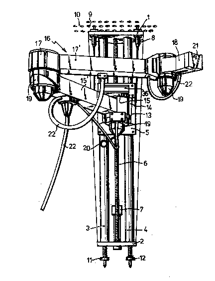
fig. 1 shows, in perspective, an apparatus for inspecting and
repairing without auxiliary tool, and
i
2~ figures 2-4 show a rear view, a plan view and a side view of an
auxiliary tool according to the invention.
~;` The apparatus represented in figure 1 comprises an upper plate 1
and a lower plate 2 which are connected by two guide bars 3 and 4.
A carriage 5 can be moved along the guide bars 3 and 4. Said
motion is effected in that the carriage comprise~ a screw sleeve
(not shown) that is mounted on a spindle 6 extending through the
carriage 5, which spindle can be rotatably driven by a drive means
7.
; The~top plate 1 comprises two span fingers 8 that can be fixed in
passageR 9 of a tube sheet 10 of the boiler. The term span fingers
is understood to refer to fixing means that can be inserted when
- they are of smaller dia~eter and that can expand after insertion,
35 J Yo that a firm fixture between the two parts can be obtained.
.
_ . .

2006942
The bottom plate 2 comprises two vertically adjustable support
legs 11 and 12, with the aid of which the apparatus can be elong-
ated in order to insert the span fingers 8 into the passages 9.
The carriage 5 comprises a receiving dovetail portion 13 devised
in the known manner for receiving an inserting dovetail portion 14
of a shoulder 15 of an arm assembly 16 which furthermore also com-
prises an upper arm 15', an elbow 17 and a lower arm 17', and a
wrist 18. Due to a drive means 19 the upper arm 15' is able to
rotate about a vertical shaft with respect to the shoulder 15, and
the same is applicable to the rotation options between the lower
arm 17' and the upper arm 15', and the wrist 18 and the lower arm
17', respectively. In this manner, together with a carriage 5 all
points in a three-dimensional space can be accurately reached.
After the parts 1-13 have been holsted through a manhole into the
boiler and have been fixed therein, the parts 14-19 are mounted
thereon with the aid of the dovetail joint 13/14. In order to be
able to release this joint again upon removing the apparatus, a
known release lever 20 has been mounted.
..
At its end, the wrist 18 comprises a receiving dovetail portion
21, arranged in the known manner, from which tools for inspecting
or repairing can be suspended.
25 ~ ;
With the aid of cables 22 and cameras and monitors (not shown) the
!, __ ~ ___,_, ____,____, _, _ ,______ ._.__,~__ ,_,," ,,, ,__.__,._ __, ._ .. _ . .. ,. , .. _
~en~ire apparatus, which can be regarded as a robot, can be remote-
controlled.
i~ ~
According to the invention, the receiving dovetail portion 21 of
the wrist 18 can also be used for positioning an in~erting dove-
tail portion 24 of an auxiliary tool 23 represented in figures
2-4.
35 ~' The auxiliary tool 23 comprises two guide bars 27 connected by end
partitions 25 and 26. A screw spindle 29 is positioned between the
....
c .
... ' . , . - ~
.
.
: i : : , , - -
.~ . . ' -
. . ,
,

2006942
guide bars, which spindle can be driven by a drive means 30, so
that with the aid of a screw sleeve fixedly mounted into the table
31, the table can be displaced back and forth along the guide
bars. The conduits necessary for driving the carriage are con-
nected to a code transmitter 32 and extend through a cable gutter
33 to the drive means 30.
The inserting dovetail portion 24 of the auxiliary tool 23 is
mounted on the outside of a vertical portion of a corner piece 34.
The horizontal portion of the corner piece 34 is mounted under the
table 31 and below this horizontal portion there is an anchoring
piece 35 that can end up of its own accord in a yoke 36 mounted on
the shoulder 15, indicatea by a dotted line in figure 4, that is
if the robot is correctly remote-controlled. Once the anchoring
piece 35 is placed in the yoke 36, then the anchoring piece can
- expand so that a firm connection to the yoke is established.
Additional span fingers 37 and 38 are unted onto the end parti-
tions 25 and 26 of the auxiliary tool 23, so that the robot can be
2~,0 temporarily suspended, as it were, from the additional span
fingers 37 and 38, after which the span fingers 8 of the upper
plate 1 can be programmed to be transferred to another set of
~; passages 9 of the tube sheet 10. With the invented auxiliary tool
the robot can thus be transferred rapidly to another position with
25~ respect to the tube sheet, so that the tubes in which the span
fingers 8 of the upper plate were located can also be inspeated or
repairedO
. : :
Perhaps needless to say that during these operations numerous pre-
30~ cautions have to be observed in order to prevent radio-actlve con-
tamination of environment and personnel. One of the precautions is
that sensors 39 can be mounted on top of the end partitions 25 and
25, which sensors assess whether the auxiliary tool 23 has accur-
ately arrived at its destination.
35 '
~ he end partitions 25 and 26 are exchangeable so as to have the
.
,, . . , . . , ., ,: ,
.: '' ` ' . . : . . '.
'~ ,. :

2006942
additional span fingers 37 and 38 at the correct pitch and dia-
meter with respect to the passages 9 of the pipe plate 10.
Other embodiment than those represented by the drawing may also be
within the scope of the claims.
~!~
. .,
1,
: ,~.
: , ~
: ~ .
.
'~' ' ; , . :,' . ' .
'
'' .' . ` ' ~ : ' ' ' ' ,
- " ' '
'. , . ' : ' ; '
' ............................................... .

Dessin représentatif
Une figure unique qui représente un dessin illustrant l'invention.
États administratifs

2024-08-01 : Dans le cadre de la transition vers les Brevets de nouvelle génération (BNG), la base de données sur les brevets canadiens (BDBC) contient désormais un Historique d'événement plus détaillé, qui reproduit le Journal des événements de notre nouvelle solution interne.

Veuillez noter que les événements débutant par « Inactive : » se réfèrent à des événements qui ne sont plus utilisés dans notre nouvelle solution interne.

Pour une meilleure compréhension de l'état de la demande ou brevet qui figure sur cette page, la rubrique Mise en garde , et les descriptions de Brevet , Historique d'événement , Taxes périodiques et Historique des paiements devraient être consultées.

Historique d'événement

Description Date
Inactive : CIB en 1re position 1999-09-27
Inactive : CIB enlevée 1999-09-27
Le délai pour l'annulation est expiré 1997-12-29
Demande non rétablie avant l'échéance 1997-12-29
Inactive : Abandon.-RE+surtaxe impayées-Corr envoyée 1996-12-30
Réputée abandonnée - omission de répondre à un avis sur les taxes pour le maintien en état 1996-12-30
Demande publiée (accessible au public) 1991-06-29

Historique d'abandonnement

Date d'abandonnement Raison Date de rétablissement
1996-12-30
Titulaires au dossier

Les titulaires actuels et antérieures au dossier sont affichés en ordre alphabétique.

Titulaires actuels au dossier
VERMAAT TECHNICS B.V.
Titulaires antérieures au dossier
HUIBRECHT PIETER VERMAAT
Les propriétaires antérieurs qui ne figurent pas dans la liste des « Propriétaires au dossier » apparaîtront dans d'autres documents au dossier.
Documents

Pour visionner les fichiers sélectionnés, entrer le code reCAPTCHA :


Pour visualiser une image, cliquer sur un lien dans la colonne description du document (Temporairement non-disponible). Pour télécharger l'image (les images), cliquer l'une ou plusieurs cases à cocher dans la première colonne et ensuite cliquer sur le bouton "Télécharger sélection en format PDF (archive Zip)" ou le bouton "Télécharger sélection (en un fichier PDF fusionné)".

Liste des documents de brevet publiés et non publiés sur la BDBC .

Si vous avez des difficultés à accéder au contenu, veuillez communiquer avec le Centre de services à la clientèle au 1-866-997-1936, ou envoyer un courriel au Centre de service à la clientèle de l'OPIC.

({010=Tous les documents, 020=Au moment du dépôt, 030=Au moment de la mise à la disponibilité du public, 040=À la délivrance, 050=Examen, 060=Correspondance reçue, 070=Divers, 080=Correspondance envoyée, 090=Paiement})


Description du
Document 
Date
(aaaa-mm-jj) 
Nombre de pages   Taille de l'image (Ko) 
Abrégé 1991-06-28 1 20
Dessins 1991-06-28 2 40
Revendications 1991-06-28 2 66
Description 1991-06-28 5 186
Dessin représentatif 1999-07-13 1 26
Taxes 1995-12-13 1 64
Taxes 1994-11-29 2 102
Taxes 1993-11-24 1 40
Taxes 1992-12-08 1 42
Taxes 1991-11-25 1 53