Note : Les descriptions sont présentées dans la langue officielle dans laquelle elles ont été soumises.
2007iS0
- 1 - LD 10,002
FORWARD ILLUMINATION LIGHTING SYSTEM FOR VEHICLES
BACKGROUND OF THE lNV~. ~ lON
The present invention relates to a lighting
system having a moveable optical member arranged between
lens elements mounted across a vehicle and optical
fibers emitting light from one of their ends which is
generated by a high brightness light source, wherein the
movement of the optical member alters the apparent
optical position of the fibers relative to the lens
elements in such a manner so as to provide all of the
forward illumination needs of the vehicle.
U.S. Patent No. 4,810,172, issued March 7,
1989 to Davenport et al and assigned to the same
assignee as the present invention, discloses a lighting
system that utilizes a high brightness light source
which is coupled to fiber optics. In one embodiment,
the lighting system includes two high intensity light
sources which are respectively coupled to a first and a
second plurality of optical fibers. Both pluralities of
optical fibers are positioned relative to lens members
mounted across a vehicle. The first high intensity
light source provides the low beam forward illumination
of the vehicle and the light from the second high
intensity light source provides the high beam forward
illumination of the vehicle. Although the lighting
2007150
- 2 - LD 10,002
system disclosed in the aforementioned U.S. Patent No.
4,810,172 serves well the needs of the vehicle, it is
desired that a lighting system be provided that needs
only one high intensity light source while still
providing both the low beam and high beam forward
illumination needs of the vehicle.
Accordingly, it is an object of the present
invention to provide a lighting system that utilizes
only one high intensity light source while still
providing high and low beam forward illumination for a
vehicle.
It is a further object of the present
invention to have the one high intensity light source
also provide the forward directional illumination
associated with the cornering lights and fog beam
illumination of the vehicles.
SUMMARY OF THE lNv~ ON
The present invention is directed to a
lighting system having an optical member which is
moveable in such a manner so as to provide all of the
forward illumination needs for a vehicle that is
generated by a single high intensity light source.
The lighting system comprises the high inten-
sity light source capable of being selectively energized,
a plurality of optical carrying devices, a plurality of
lens elements positioned relative to the ends of the
respective optical carrying devices, and a moveable
optical device interposed between the ends of the optical
carrying devices and lens elements. The optical carrying
devices each have one end predeterminately coupled to the
light source with the other end emitting light when the
high intensity light source is energized. The moveable
device is preferably of a transparent material of a
predetermined thickness and having a predetermined
26~1SO
-3- LD 10,002
index of refraction with its imposition altering the
apparent optical position of the optical carrying
devices relative to the lens elements.
BRIEF DESCRIPTION OF THE DRAWING
Fig. 1 is a schematic illustration of one
embodiment of the present invention related to a
lighting system that provides the forward illumination
including cornering illumination of a vehicle.
Fig. 2 illustrates an arrangement of an
illumination device related to the present invention.
Fig. 3 is a top-view which illustrates an
arrangement of the connectors housing optical fibers, a
moveable optical member, and lens elements all related
to the present invention.
Fig. 4 primarily illustrates the interrelationship
between a wedge member and the real and apparent
position of the ends of the optical fibers relative to
lens elements which are involved in generating the low
and high beam illumination related to the present
invention.
Fig. 5 illustrates the effect of the alteration of
the apparent position of the optical fibers (object)
related to the high and low beam (images) developed by
the present invention.
Fig. 6 illustrates the interrelationship between a
rotating flat optical member altering the apparent
optical position of the ends of the optical fibers
involved in generating the low and high beam
illumination related to the present invention.
DETAILED DESCRIPTION OF THE PREFERRED EMBODIMENTS
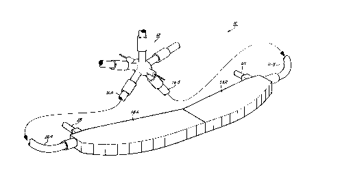
Referring to the drawing, Fig. 1 illustrates a
lighting system 10 of the present invention that is
particularly suited to provide the forward illumination
including the cornering and fog beam illumination needs
2007 1 50
- 4 - LD 10,002
for aerodynamically styled vehicles.
The lighting system 10 has a high intensity
light source 12 that provides all of the lumens to
serve the forward, rearward, and interior
illumination needs for a vehicle. The present
invention is primarily related to providing the
forward illumination of the vehicles and therefore
the facilities of the light source 12 related to such
illumination is only to be described. The light
source 12 may be of the type described in U.S. Patent
No. 4,958,263 , issued September 18, 1990 , Davenport et
al and assigned to the same assignee of the present
inventlon .
The low and high beam forward illumination
along with the cornering and fog beam illumination of
the vehicle is provided by illumination devices 14A
and 14B that are respectively coupled to light source
12 by means of optical carrying devices 16A and 16B.
The illuminating devices 14A and 14B, each have a
connector 18 that routes electric power to an
electrically activated device 20 to be described with
regard to Fig. 2. The optical carrying devices 16A
and 16B may have various embodiments which are
described in previously mentioned U.S. Patent
No. 4,958,263 .
The illumination devices 14A and 14B each
have an arrangement that is shown in more detail in
Fig. 2 for illuminating device 14A. Fig. 2 shows an
arrangement of the elements tabulated in Table 1.
200~150
-5- LD 10,002
TABLE 1
Optical
Carrying Rectangular Moveable Lens
Connectors Array Member Elements
221 241 2611 2612 28
222 241 2611 2612 282
223 241 2611 2612 283
224 242 2621 2622 284
225 242 2621 2622 285
226 242 2621 2622 286
227 243 2631 2632 287
228 243 2631 2632 288
229 243 2631 2632 289
221o 243 2631 2632 281o
Fig. 2 partially illustrates the illumination device
14A as comprising an arrangement of connectors 22, an
optical member 26 and lens elements 28. The connector
arrangement 22 is comprised of a plurality of connectors
221, 222...22n which lodqes the fiber optical
cables branched off from the optical carrying device
16A. The ends of the fiber optics of the connectors
221...22n emit light through respective apertures
241, 242 or 243 given in Table l. Fig. 2 further
partially illustrates illumination device 14A as
comprising an optical member 26 having a plurality of
sectionS 2611~ 2612---26nn some of which are
tabulated in Table l, and a plurality of lens elements
' -6- 2007 1 50 LD 10,002
281, 282...28n, some of which are also tabulated in
Table l. The optical member 26 may have three
em~odiments 26A, 26B (shown in phantom~, and 26C
(shown in phantom) that may be respectively related to
the low/high beam illumination, concerning illumination
and fog beam illumination each of a vehicle. For such
embodiments, the light emitted from the connectors may be
shared by the three arrangement by means of appropriate
upward, downward, or sideward movement of device 20 or
separate connectors (not shown) may be provided for each
such arrangement.
For the embodiment shown in Figure 2, the three
apertures, 241, 242, and 243 are of increasing
relative dimensions. Such an arrangement of apertures
provides a tapered array of which the maximum light of
illumination device 14A is transmitted from optical
devices of 221, 222, 223, with a lesser amount from
optical devices of 224, 225, 226, and then with an
even lesser amount from devices of 227, 228, 229
and 221o. The lens elements 281.... 28n that
cooperate with the optical fibers of 221...22n may be
of the type described in the aforementioned
U.S. Patent No. 4,958,263 .
The principles of the present invention are
particularly related to the optical member 26 that is
connected to the device 20 which may be actuated and
moveably position the associated section 261l...26nn
of members 26A, 26B and 26C. The device 20, having
applied to it the electric power of connector 18, may
cause the sections 261l... 26nn to be moved in a
sideward, upward or downward manner so that, for example,
sections 2611~ 2621 and 2631 are first interposed
between the connectors 22 and the lens elements 28, and
then sections 2612, 2622 and 2623 are so
interposed. The related sections 2611, 2621 and
2631 of 26A of Fig. 2 have a clear opening to allow
h ~ ,
~0()7~50
' -7- LD 10,002
light to pass therethrough unimpeded, whereas, related
seCtions 2612~ 2622 and 2632 are of a tranSparent
medium, such as glass or plastic devoid of any opening.
The imposition of the moveable device 26A, in
p icular 2612~ 2622 and 2632, alter the apparent
or optical position of the related optical devices of
connectors 22 relative to the lens elements 28 which
alteration may be first described with reference to Fig.
3.
Fig. 3 is a top-view which illustrates two light beam
patterns 24A that are transmitted from the rectangle
aperture 241 of optical connectors 222 and 223.
The beam patterns 24A each pass through the opened
portion of flat section 2611 of optical member 26A
and impinge upon respective lens elements 282 and
283. The flat section 2611 of 26A is interposed
between the optical fibers of connector 22 and lens
element 28 and is related to the generation of the low
beam pattern of the forward illumination of the vehicle.
The interaction of the other related section of member 26
such as 2612 having a wedge shape may be described with
reference to Fig. 4.
Fig. 4 illustrates a portion of the optical wedge
member 2612 that is interposed between the light rays
related to beam pattern 24A and the lens element
282. The wedge member 2612 has a predetermined wedge
angle shown in Fig. 4, for example, as 5~. The amount
of deviation between the incident light rays striking the
wedge member 262 and those rays which are refracted
before emerging from wedge member 262 is a function of
the wedge angle, the thickness, and the index of
refraction, all of wedge member 262. The wedge angle,
thickness, and index of refraction of the wedge number
2612 may have respective ranges of about 3 to 30
degrees; 1 to 10 mm; and 1.3 to 1.8.
The practice of the present invention may first be
2007~50
-
-8- LD 10,002
described with reference to the operation of Figure 4
devoid of a wedge member 2612, that is, the operation
of light emitted from the aperture 241 and passing
directly through the open portion of related member
2611. For such an operation, a point source of light
rays is illustrated at its real position Q as it is seen
from or presented to lens element 282. The point
source Q is meant to represent the concentration of light
emitted from central region of the aperture 241. The
point source Q generates a cone of light having an upper
path 32A (solid line), middle path 34A (solid line),
and lower path 36A (solid line). The imposition of the
wedge member 2612, by the activation of device 20 of
Fig. 2, causes the position of the point source of Fig. 4
as it is seen or as presented to the lens 282, to move
from point Q(real) in an inward and upward manner to
point Q'. The imposition of the wedge member 2612
causes the light rays to be refracted inward and downward
by wedge member 2612 as represented by upper path 32B
(phantom), middle path 34B (phantom) and lower path
36C (phantom) which further continue on respectively as
32C~ 34C and 36c. The path of the light rays
32c, and 34C~ and 36C are representative of the low
beam illumination pattern of a vehicle, whereas, the path
of light rays 32A~ 34A and 36A are representative
of the high beam illumination. The Q' point of the
emitting light rays related to the low beam pattern, is
constructed by extending lines 32D~ 34D and 36
from their respective locatins 32E~ 34E and 36E
from which they emerge from wedge member 2612 back
toward and intersecting at Q'. The point Q' forms the
apparent position of the light rays related to the
moveable wedge member 2612 of Fig. 4. The inward
movement (Q to Q') is represented in Fig. 4 by a distance
38 in the range of about 1 mm to about 3 mm, whereas, the
upward movement (Q to Q') is represented by a distance 40
200'715C~
-9- LD 10,002
in the range of about 2 mm to about 10 mm. The overall
effect of the imposition of wedge member 2612 is to
cause a slight shift in the focus of the lens. By
choosing the distances properly, the low beam may be
S spread slightly and the high beam may be focussed more
sharply.
The effect of the imposition of the optical wedge
2612 as it relates to the low and high beam patterns
may be further described with reference to Fig. 5. Fig.
5 illustrates the optical effect related to forward
illumination of a vehicle on the position of the image
(high beam 42 or low beam 44) on changing the real
position (Q) or apparent position (Q') of the object
(central region of light emitted from aperture 241).
Fig. 5 is only representative of the light rays related
to lens elements 282, whereas, in actuality the light
rays related to all of the lens elements 281...28n,
each generating a rectangular image, are superpositioned
onto each other so as to form the composite low or high
beam illumination pattern of the vehicle.
Fig. 5 illustrates the effect of the imposition of
the wedge member 2612 at a location 44 in front of lens
element 282. The light rays being emitted from
position Q are transmitted by lens element 282 50 as to
form part of the high beam pattern 42, whereas, the light
rays being emitted from position Q' are transmitted by
lens element 282 50 as to form part of the low beam
pattern 44. The paths related to the light rays of
positions Q and Q' are as previously described with
regard to Fig. 4.
The operation of Figs. 2, 3, 4 and 5 related to the
seCtions 2611~ 2621 and 2631 having an opened
portion to allow the light to be emitted from the ends of
the optic fibers of connectors 221...22N is also
applicable to such sections having a flat transparent
portion for intercepting such emitted light with the
2(~ 15~
-10- LD 10,002
exception being that the intercepted light rays are
refracted downward and the apparent point source Q' is
moved inward in a substantially horizontal manner
relative to the real point source Q. The amount that the
point source is altered from Q to Q' is a function of the
thickness and index of refraction of the flat transparent
sections 2611, 2621 and 2631.
The principles of the present invention that have
been described for a wedge member 2612 are also
applicable to a flat optical member which is rotated and
may be described with reference to Fig. 6. Fig. 6
illustrates the imposition of a flat optical member
2611 (shown in phantom) between the connection region
241 and the lens member 282 (not shown) in a similar
manner as previously described for wedge member 262 ~f
Fig. 4. The flat member 2611 is shown as positioned in
a vertical manner (A) perpendicular to the optical axis
46 of lens 282 (not shown) and causes the position of
the light source of be alterated from Q (not shown) to
Q'. The flat member 2611 is also shown (B) as rotated
by an angle 0 relative to the center of rotation 48 of
member 2611 positioned along the optical axis 46 of
lens element 282. The rotation of the mem~er 2611
may be accomplished with an activation device similar to
device 20 except that member 2611 is moved in a
rotating manner rather than the linear movement of the
wedge member 2612 previously described for device 20.
The light rays related to the point source Q'
striking member 2611(B) have an upper path 46A (solid
line) a middle path 48A (solid line) and a lower path
50A (solid line). The incident rays 46A~ 48A and
50A encountering the rotated member 2611(B) are
refracted, respectively shown as rays 46B~ 48B and
50B (all in phantom) and emerge therefrom as rays
46c, 48C and 50C (also all in phantom)
respectively. The Q" point for the emitting light rays
200715~)
-11- LD 10,002
related to the rotated member 2611(B) is constructed by
drawing lines 46D~ 48~ and 50D back from locations
46E~ 48E and 50Et respectively, from which light
these rays emerge therefrom and intersecting thereat
their origin (Q'').
The rotation of the flat member 261 causes the
apparent or optical position of the light rays emitted
from the central region of aperture 241 as presented to
lens member 262, to move Q' to Q''. The overall effect
of the imposition and rotation of optical member
2611(B), is that the light rays emitted by the optical
fibers at the central region of the aperture 241 are
directed inward so that the light pattern transmitted by
lens 282 may be altered from the low beam illumination
to the high beam illumination of the vehicle. The
illumination patterns generated by the operation of Fig.
6 are similar to the patterns of Fig. 5 previously
discussed with regard to Fig. 4.
The practice of the present invention, hereinbefore
described, for generating the low and high beam forward
illumination is equally applicable for generating the
forward illumination desired for the cornering lamps.
For such cornering lamps, the high beam illumination
described with regard to Figs. 3, 4, 5 and 6 may be used
as the direct light desired while the vehicle is
proceeding in a direct manner, whereas, the low beam
illumination described with regard to Figs. 3, 4, 5 and 6
may be used as the spread light desired while the vehicle
is proceeding through a curve or in a turning manner.
The activation of a device related to the cornering
lumination may be similar to device 20 associated with
the wedge member 2612. The activation of such a device
may be accomplished by motion sensing means that
anticipates the turning of a vehicle so that the
cornering lamps may then generate the spread beam
illumination pattern.
2007150
-12- LD 10,002
The cornering illumination may be developed by
choosing the appropriate parameters and cooperation of
device 20, optical member 26B and lens elements
281...28N all generally illustrated in Fig. 2. For
example, the lens elements 28 located in the frontal area
near each side portion of the vehicle may be selected to
transmit the cornering illumination, and connectors 22
proximate to the selected lens elements may be selected
to supply the related generated light, whereas, the
associated sections of optical member 26B, similar to
2611 and 2612 previously described, may have
appropriate parameters selected to develop the desired
cornering illumination. For such illumination, the
operation of device 20 is selected so that optical member
26B is the moved in and out of imposition with its
related connectors 22 upon the appropriate occurrence of
operator commands.
The practice of the present invention may also
develop fog beam illumination by choosing the appropriate
parameters and cooperation of device 20, optical member
26C and lens elements 281...28N all generally
illustrated in Fig. 2. For example, the lens elements 28
located in the central frontal area of the vehicle may be
selected to transmitted the fog beam illumination, and
connectors 22 proximate to the selected central lens
elements may be selected to supply the related generated
light, whereas, the associated sections of optical member
26C, similar to 2611 and 2612 previously discussed,
may have appropriate parameters, such as the color
yellow, selected to develop the desired fog beam
illumination. For such illumination, the operation of
device 20 is selected so that optical member 26C is
moved in and out of imposition with its related
connectors 22 upon the appropriate occurrence of operator
commands.
It should now be appreciated that the practice of
200~7~50
-13- LD 10,002
the present invention having various flat and wedge
optical imposition embodiments provide for a single
high intensity light source that generates the light
energy for the fog light illumination, and the forward
illumination including low and high beams along with
cornering illumination.
It should be further appreciated that the optical
member 2611 or 2612 may be interposed between the
connectors 221...22n of the optical fibers having
ends for emitting light and the lens elements
281...28n in a linear manner or the optical member
2611 may be so interposed in a rotated manner. The
amount of derivation between the real and apparent
positions of the light emitting optical fibers of
connectors 221... 22n, relative to the lens elements
281...28n transmitting the low and high beam
illumination patterns, is a function of the parameters
selected for the optical members 2611...26nn.