Note : Les descriptions sont présentées dans la langue officielle dans laquelle elles ont été soumises.
2~7Z5~
. ~
~ield of the Invention
The invention relate3 generally to c.onveyance
of materials by virtue of hydraulic means and, more
specifically, to a device for hydraulic con~eyance
of loose materials.
~he invention i~ ~ucce~fully applicable in the
min~ne indu~try, in civil engineering, metallurgy,
and in the farming indust~y for hydraulic conveying
o~ loo~e material3 over long distance3.
tO Of ~pecial interest i~ practical applic~tion of
the industry ~or hydraulic c~nveyance of ~uch loose
materiAl~ as mineral raw materlals, in dres~ing
practice when m;n;n~ placer and ~re dep~sit~ of the
opencast and underground mining techniques, a~ w~ll
a~ in c~n~truotion of hydraulic engi~eering
~tructure~.
Baokground of the Invention
~ t the present time, devices for hydraulic con-
veyance of loose material~, comprising a chamber pro-
vided with a loose material charging unit and a ~lur~ry di~char~ unit and making integrQl part o~ hyd-
~aulic.conveyance in~tallations incorporating additi-
onsl components ~uch a3 water pump~, pipeline~ ~top
~alves and fittings, should meet a number of require-
ments including reliable operation o~ such devicesruling out.clogging of the discharge unit with tha
~ 2 --
2~07253~
loose material, or hanging o~ the looae material in
the chamber, which stem~ from the atrength of the
chamber; as well as efficient chargi~g o~ the loose
material resulting from minimlzed amount~ of the
loo~e material particle~ carried away with the liquid
being discharged during ~illing and mln;m;~ed amount
o~ air fed into the chamber. Another requireme~t to
be met resides in ef~icient ~lurry discharge due to
l~w claa3ifying of the looae m~terial which i9 uni-
formly fed to the di~ch~rge unlt.
One ~tate-of-the-art ~evice for hydraulic convey-
ance of lo~ae rnaterial~ i~ k~own (SU, A, 615,015) to
comprise a vertically in3talled chamber having a cy-
lindricQl ~hape and pr~Yided wi th a pipe for charging
the looae material in the form of alurry, which pipe
al~o aerves aa a pipe for di~charging the slurry lnto
a pulp ~eedin~s pipe, a pre~sure liquid ~low îeeding
pipe, and a liquid discharge pipe located in the top
portion of the chamberO
rllo m;nlm;ze the amount of the loose materi~l
particle~ carried away w~th the li~uid being diseharg-
edl the chamber i~ charged in an upward ~low" while
the liquid being diacharged i~ separated from the
looce material bein~ charged, by meana of a ~cree~
w~:Li¢h is adapted to move langthwi~e the chamber as it
i~ bei~g chargeà from below and intended to reduoe
the amount of the loo~ material particle~ carried
-- 3 --
- . . .
2~7~
aw~y by the liquid' being discharged.
Pro~ision of a mvvable ~creen in~ide the chamber
renders the construction more ~ophi~ticated and re-
dure~ it~ reliability. Moreover, chargin~ the ~lurry
5 in an upward Xlow re~ult3 in inten~e classifying of
the loo~e naterial in term~ af den~ity a2ld size,
which i~ also the ca~c during di~charge of the cham-
ber, with attendant instability of the ~lurry density.
Thus, the aforedescribed device fails to provide
the conveyance of stable den~ity ~lurry to the pulp
~eeding pipe, while a reduction in the amount of the
lo~e m~terial carried away by the liquid being dis-
charged i9 attained at the expense of reliability of
the device,
One more prior-art device for hydraulic convey-
ance o~ 1003e material~ (SU, A, 391,974) is known to
compri~e a vertically i~stalled chamber havin~ a cy-
lindrical ~hape. Preparatory to charging, part of the
liquid i9 expelled from the chamber through a pipe
. 20 pro~ided in it~ bott~m portlon~ in order to ~inimize
the ~amount of the loo~e material carried away~
To reduce the cla~ifying taking place, when the
ohamber i~ being di~charg~d, the pre~ure liquid flow
i8 dlvided into two ~low~ fed into the chamber
25 throu~h two pipes one of which is located in the top
portion of the chamber.
The additio~al operations ~uch a~ dr~;n;ng the
-- 4 --
2~ 7
liquid preparatory to charging and delivery of the
part OI the liquid flow durin~ discharge, consider-
ably reduce the e~iciency of the device and render
it~ control 9y9tem more ~ophi~ticated. At lea~t three
chambers are required to enable continuou~ di~charge
of the ~lurry into the pulp ~eeding pipe. Ths afore-
mentioned deviGe feature~ low reliability re~ulting
from the ~act that the chamber may only be charged
with dry or dehydrated materi~l tending to hang up i~
the chamber, which promote9 clogging o~ the di~charge
pipe if water content of the loose material i9 too
low.
By-pa~ing part of the pressure liquid flow up-
ward the chamber reduces the ~tability of slurry dens-
ity, becau~e in the cour~e of discharging the ratiobetween the pre~ure liquid flow rates i~ changed due
to increa~ed rate of the pre~ure li.quid make-up ~l~w.
Effective control over the ratio between the rates o~
the main flow and the make-up (upper) flow o~ the
pres~ure liquid iJ virtually un~ea~ibleO
Known pre~ently are other device~ for hydraulic
- conveyance of loo~e materials (SU, A, 612,873; SU, A,
~98,000) where attempt~ have been made to reduce the
: amount o~ the loo~e material partiele~ carried away
during chargi~
In the ~ormer of the embodiment~ mentioned here-
.
inbefore, air i9 force fed into the top portion of a
, .
2~ 72~)
, . ,
cylindrically ~haped chamber during di3charge. A3 aresult, after discharge is o~er7 the chamber remai~a
empty without the need to drain the liquid.
However, the above-de~cribed device of~er3 but a
low margin of ~afety because of po~ible loss of lsak-
-tightnesa of the chamber, with attendant hazard of
compreased air bur~tingO Power consumption of the de-
vice i~ far too high to e~fect hydraulic conveyance
over long distances. Thia predetermines the use of a
compressor having a power capacity greater than that
q~ the primary preaaure unit - the water pump. Fur-
thermore, the device suffer~ fr~m low productlon effi-
ciency resulting from the fact that the de~ice can
.. . . .
only be charged when the pressure in~ide the chamber
15 i3 reduced to the atmospheric, pre~sure.
In the latter of the devioe~ mentioned herein-
before, the ¢hamber is made in the form of a hydrau-
lic cyclone, which allow~ the discharged li~uid to be
separated and diverted while the slurry i~ b~in~
oharged into the chamber. In ~uch an embodiment ? the
top portion o~ the chamber ~perating as a hydraulic
cy~,lone, i~ aubae~t to ~ast wear, which ln tur~ a~-.
fect~ adver~ely the chambar ~trength characteristic3.
In the above-ai~cusaed devices, the chamber dis-
25 ¢harge proce~ accompanied by clas~i~ying o~ theloa~e material taking pl~ce as it i~ being expelled
~rom the chamber by the liquid. The clas3ifying
2~ 2~
occurs due to segregation of the lo~e material a~ it
de3cends, the ~maller and lighter particle3 being
~u.~pended.
Still another device for hydraulic conveyance of
loose material~ (SU, A, 1,~68,496) is known to com-
pri3e a toroidal chamber having a meridianal plane
a~d an equatorial plane a~d provided with pipes for
¢harging the loose material and discharging the li-
quid u~ed for hydraulic conveyance, both ~ the pipe~
being arranged on one side with respect to the meridi-
anal plane of the toroidal chamber, and with a slurry
di~charge de~ice arran~ed on the other ~ide with res-
pect to the meri~;~n~l plane, the equatorial plane of
the chamber being di~posed vertically.
The toroidal ~hape af the chamber contributes to
it~ higher ~trength and m;n;m;ze~ ~pecific metal con-
~umption~
Loose materials can be charged into the toroidal
chamber in the for~m of ~lurry by loading it in a
2Q ~tandstill zone on the ~urface of the throat of the
toroidal chamber9 that i~ on the inner wall in itq up-
per portion. ~rom the in~er wall, the loo~e material
~lips down until lu~p~ of the material drop down in a
re~trained manner, thu~ min;~;zi~g the amount of the
-
25 loo~e material particle~ carrled away by the liquid
di~charged becau~e additional energy is required to
bre~k the particle~ loo~e frsm the bulk of the materi-
- 7 -
2~72~)
a~. Be3ide3, the portion of the toroidal chamber di~-
posed above it~ throat u~ed for charging the loo~e ma-
teriall ha3 ~ larger cro~ ection than the aforede~-
c~ibed chamber~ having di~ferent ~hape~ but the ~ame
5 volume~ Because of thi~ the uplift rate of the li-
quid being di~¢hargad i3 la~ than that in an~ of the
a~olre-mexltioned devicesa and it tends to decline
- still further a~ the di~tance between the cylindrical
portions of the chamber or the chamber throat radius
increa~e~.
However, as the operating efficiency of such de-
vices increases, which inv~lves greater flow rate~ of
the slurry being handled, the amount of the loose ma-
terial particles carried away by the liquid di~charg-
ed tend~ ts increa3e as well, ~ince the material
charging portion of the throat fails to sccept all
the loose material fed in, with the result that part
of the loose material is repelled by the throat ~ur-
~ace, thu cau~ing 31urry ~wirling flows.
A~ compared to chambsr~ of the other shapes des-
cribed hereinbefore, use of a toroidal chamber
enable~ the loo~e material to be more uniformly fed
to the di3charging unit, and the loose material i~
le~s liable to ola~sifyin~ by virtue of the fact that
the loo~e material i~ circumfluent the lower portion
of the throat 3urfaoe in a downward flow, where~ the
liquid i~ circumfluent the ~ame~oat ~ion in an u~rd
-- 8 --
2~7;~
.
flow. Such an arrangement of the flnw~ make~ it pos3i-
ble to reduce the resistance of the liquid to the
loose material because of the fact that th~ major li-
quid flow is formed nearby the throat wall, viz.,
clo~e to the inner wall of the chamber. Ho~ever, in
common with the aforede~cribed device~, a~ the height
of the vertical cylindrical portion~ n~ th~ chamber
increa~e~? the loo~e material i~ liable t~ be ~egre-
gated by particle ~ize and den3ity, as for hei~ht of
these portions, which i~ cau~ative of cla~sification
and reduced ~tability of the ~lurry den~ity.
Brief Summary of the Invention
It is therefore an object o~ the present invent-
ion to provide a device for hydr~ulic aonveyance of
loo~e m~terials, which would en~ure a reduction in
the amount o~ the loose material carried away by the
~ liquid discharged, when th~ loo~e material i~ being
ch~rged into the chamber, and an increa~e in the 3ta- -
bility of den~ity of the slurry being handledO
With the foregoing and other objects in view
the present invention thus reside~ in the ~act that
in a device for hydraulic conveyance of loose m~teri
al~, compri~ing a toroidal ch~mber having a meridian-
~1 plane and an equatorial plane and provided ~ith
pipe~ for charging the loo~e material and di3charging
the liquid u~ed for hydraulic conveyance, both of the
pipe~ being arr~nged on o~e ~ids with respect to the
_ 9 _
2 ~ ~7
meridianal plane of the toroidal chamber, and with a
~lurry discharge device arranged on the other 3ide
with re3pect to the meridianal plane, according to
the invention, an angle defined between the equatori~
al plane o~ the toroidal chamber and a horizontal
plane, be within a range of
~ o~ 90~,
where oC i8 the angle defined between the equatorial
plane of the t~roidal chamber and a horizont-
al plane;
i~ the angle of internal friction of the
lo~se material t when saturated with the li-
quid u~ed ~or hydraulic conveyanae.
It is expedient that in a device for hydraulic
conveyance, according to the invention, the an~le de-
fined between the equatorial plane o~ the t~roidal
chamber and a horizontal plane, be within a range of
40~~ 450
It is favourable that in a device *or hydraulic
conveyance, according to the invention, the toroidal
chamber be provided with a partition plate ~itted in
its upper part and disposed substantially in the equa-
torial plane so a~ to ~orm two spaces arranged one be-
low the oth~r, the lower ~paoe being ass~ciated with
the loo~e material charging pipe~ while the upper
space communicates with thei liquid discharge pipe.
It is advantageous that a device for hydraulic
~ 10 -
2 ~7
conveyance, according to the invention, be provided
with a loose material ~low shaper and/or a di~charge
liquid flow shaper accommodated inside the respective
~paces.
It i~ effective that in a device for hydraulic
con~eya~ce, according to the invention, the shaper
forming the flow of the loose material and the shaper
forming the flow of the liquid being disch~rged are
made each i~ the form of at lea~t one plate set with
respect to the partition plate at an acute whose vor-
te~ is directed towards the upper part of the toroid-
al chamber,
It i~ reasonable that in a device for hydraulic
conveyance, according to the invention, when the
3haper~ forming the flow3 of the loose mBterial and
the liquid being discharged are made in the form of 8
plurality of plates, the pla~te~ be disposed at sub-
st~ntially the same acu-~e angle with respeot to the
partition plate~ -
In a device for hydraulic conveyance of loo~e ma-
terials, when an angle de~ined between the equatorial
plane o~ the toroidal chamber and a horizontal plane,
falls within the above-specified limits, the current
of the loose material being charged will divide into
two flows running down the chamber walls along the
wa~l portion~ situat6d bel~w the equatorial plane~
until the chamber i~ filled completely~ As the li~uid
. 11 -
2 ~ ~7
i~ being di~charged, no vigorou~ carryaway of the
loose material take3 place 3ince the bulk of the
loose material charged i~ not in su~pen~ion, Inclinat-
ion of the chamber within the above-speciîiea limits
during discharge provide~ a ~ub~tantial reduction of
the classifying o~ the loose mat~rial over the cham-
ber volume, hence better tability o~ den~ity of the
31urry handled, by virtue of the fact that the loo~e
material ~inks to the di~charging unit ~long the low-
er wall while being replaced by the liquid risingabove the loo~e material along the upper wall of the
chamber. A~ thi~ take~ place 9 interaction between the
liquid and the loose material i9 minlmi7ed. Be~ides,
the min;m1zed interaction between the replacing li-
quid and the 1Oo3e material e~ables it to be uniform-
ly fed to the di~charging unit, which add~ to ~tabili-
ty o~ the slurry den~ity.
Brief De~cription of the Drawin~s
In what ~ollow~ the pre~ent inventio~ will now
be disclo~ed in a detailed desoription of an illust-
f
r~ti~e embodiment thereo~ with re~erence to tha accom-
p~ ny; n ~ drawing~, wherein:
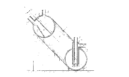
~ igc 1 i~ a general view o~ a device ~or hydrau-
lic ~onveyance o~ loose material~ (an i~ometric draw-
ing), according to the invention;
Fig. 2 i~ ~ general ~ectional view o~ a device
~725~
~or hydraulic conveyance of loose material~ taken on
a meridianal plane and showing a partition plate ar-
ranged in an equatorial plane of the chamber, and a
~h~per of the loo~e material flow fitted in the lower
chamber a~ related to the partition plate, according
to the invention;
Fig. 3 i~ a ~ectional view taken on the meridian-
al plane and ~howing the chamber with the partition
plate, the 1003~ material flow shaper and a discharge
flow 3haper fit~ed in their reqpective ~pace~, accord-
ing to the invention;
Fig. 4 is a sectional view taken on the line
IV-IV in Fig. 3 (with the chamber wall partly cut
away);
~ig. 5 i~ a ~ectional view taken on the line V-V
in Fig. 4;
Fig. 6 is a general ~chemAtic view of an install-
atlon for hydraulic conveyance featuring two devices
for hydraulic conveyance of loo~ material~, accord-
ing to the invention.
Detailed Description of the Invention
A device ~or hydraulic convsyance o~ loo~e mate-
rial~ compri~e~ a toroidal chamber 1 (Fig. 1) provid-
.. . .
ed with a pipe 2 for oharging the loo~e material and
a pipe 3 ~or di~charging the liquid, both o~ thepipe~ being arranged on on~ ~ide with respect t~ a
~ 13 -
2~)~7~S~
,.,~
merid; ~n~.l plane of the chamber 1 (the intersection
between the meri~i~n~l plane and an equatorial pl~ne
H is denoted "0")~ A slurry dischar~e unit 4 i~ ar-
ranged on the other ~ide of the meridianal plane~ The
equatorial plane H of the chamber 1 is inclined with
respect to a horizontal plane G at an angle ~ fall-
ing within a range of
~ 90~,
where ~ iB the angle of internal friction o~ the
0 1008e material, when ~aturated with the liquid used
~or hydraulic conveyance.
The slurry discharging unit 4 compris~s a pipe 5
for feeding the pressure liquid flow and a pipe 6 for
discharging the ~lurry.
The minimum angle of inclination o~ the chamber
1 is determined praceeding from the condition o~ re-
liable transfer o~ the loo~e m~terial to the slurry
.
discharge unit 4 under gravity.
If the e~uatorial plane H of the chamber 1 is
inclined at an angle ~ equal to or less than ~ , mo-
bility of the particle~ is dra~tically reduced, which
impede~ the supply of the loose material to the slur-
ry di~charging unit 4 and renders the device operat-
ion impracticable.
Studies have ~hown that even slight misalignment
bet~een the equatorial plane H and the vertical plane
leads to ~harp segregation o~ the loo~e material flow
- 14 -
2 ~ ~7
~rom the flow of the liquid discharged, which reduce~
the amount of the loose material particle3 ¢arried
away by the liquid di~charged. However, particle~ of
the loose material remain to be in su~pen~ion under
the action o~ the upward fl~w of the liquid discharg-
edg but it tends to decrea~e i~ the misalignmsnt from
the vertical plane increases still further. A ~ubstan-
tial reduction in the amount of particles suspended
is observed if cC~ 45~.
Studies have al~o demo~trated that if oC~40~,
the amount of material particle~ carried away
increases. Therefore, an optimum arrangement of the
chamber 1 will be provided when ~ falls within a
range of
40~ ~ ~ ~ 45~
If the loose material is charged in greater
amount3 or after the chamber 1 has been completely
charged, turbulent interaction between the flows of
the loose material and the liquid discharged may be
encountered. ~o maintain the l~mi nar nature of these
flow~, the ch~mber 1 is pr~vided in its upper portio~
with the partiti~n plate 7 (~ig. 2) arranged ~ubstan-
tially in the equatorial plane H ~o a8 to fo~m two
space~ 8, 9 di~posed one b81O'R the ~ther. ~he lower
space 8 communicate~ with the pipe 2 ~or charging the
loose material, while the ~pace 9, with the pipe 3
for di~charging the liquid. Lsngth l o~ the partition
~ 15 -
26)(~725~
.,
plate i3 equal to or less than the diamet2r of the
generator circum~erence o~ the chamber 1.
To maintain the flows of the loo~e m~terial and
the liquid di3charged under the condition~ cl~se to
the l~m;n~r flow, the device i~ provided with Q loose
material flow ~haper 10 and/~r a di~charge liquid
fl~w ~haper 11 (~ig. 3) accommodated in~ide the res-
pective ~paces 8, 9. The ~haper3 1~1 11 are made each
in the ~orm o~ at lea~t one plate set with re~pect to
the partiti~n plate 7 at an acute angle ~ who~e vor-
tex i~ directed towards the upper part of the chamber
1, The loose material flow shaper 10 as illustrated
in ~ig. 2 is made in the ~orm o~ one plate, while the
shaper 10 and the discharge liquid ~l~w shaper 11 as
shown in ~ig. 39 are made in the f~rm of a plurality
of plates 12 (FigA 4) and 13 (~i~3 4, 5), re~pective-
ly. All the plate~ 12 (~ig. 3) and 13 are disposed at
substantially the same acute angle . Accor~g to one of
the embodiments, the angle of inclination of the
plates 12 of the shaper 10 differs from the angle of
inclination of the plate~ 13 of the shaper 11. Magni-
tude of the angle ~ i9 selected 90 as tn prevent
clogging of the plates 12 with the loo~e material
duri~g charging, and to preclude con~qiderable resist-
ance ~f the plate~ 13 to the flow of the liquid beingdi~charged.
The lower edge~ of the plate~ 12 sre situated at
7~5~
, ,
the level o~ the lower edge of the partition plate 7
and above it, while the upper edges are ~paced a
certain di~tance apart from the walls of the chamber
1, which enable~ the looqe material flow to be freely
di~tributed in the clearances between the plate~ 12.
This di~tance m~y be equal to the diameter of the
pipe 2 for charging the loose material or be at least
three to ~ive time~ ~he diameter of the m~;ml~m ~ize
o~ the large~t ~raction of the loo~e material handled.
1Q A device for hydraulic conveyance of loo~e mate-
rial~ make~ an integral part of an inqtallation for
hydraulic conveyance. To provide for uninterrupted
operation of the device~, the in~tallation compri~e~
two or more such device~ e~ch of which i~ connected
to a low-lift quction dredge 16 via the pipe 2 and a
~lurry feeding pLpeline 14 (Fig. 6) provided with a
che¢k valve 15; to a sump 19 o~ the l~w-lift 3uction
dredge 16 via the pipe 3 and a discharge pipeline 17
provided with a gate valve 18 (not~hown in ~he figu- -
re); to a high-lift water pump 22 via the pipe 5 and
a pres~ure water conduit 20 provided with a gate
valve 21~ The pump 22 i~ oonnected t~ a main pulp
feeding pipeline 25 through the agency ~f the pre~-
ure water conduit 20 and a bypas~ water conduit 23
providad with a &ate valve 24. ~he chamber~ 1 are con-
nected to the main pulp fe~ding pipeline 25 by mea~
of the pipe~ 6, via the relief pipelines 26 provided
- 17 -
2 ~ ~7
with check valve3 27.
The device for hydraulic conveyance of loo~e ma-
teri~l~ operates a~ ~ollow~, From ths bulk being hol-
lowed ~ut by a hydraulic giant, the 1003e material i~
fed into the ~ump 19 tFig, 6) of the low~ t suction
dredge 16 and is further pumped along the ~lurry feed-
ing pipaline 14 and the pipe 2 (~ig. 1) into the cham-
ber 1 emptied of any loose material but filled with
the liquid remaining after discharge. The flow o~ the
loo~e material being charged i~ 3egregated into two
flow3 delivered to the portions of the wall of the
chamber 1 arranged below the equatorial plane H ~o
that the loose material 31ip~ down the walls whereby
the chamber 1 i~ filled. ~he exces~ liquid contained
in the chamber 1 i~ di3placed by the loo~e material
and i~ e~pelled, through the discharging pipe 3 and
the di~charge pipeline 17 (Fig, 6), to the sump 19.
The exces~ liquid i~ di~charged primarily fr~m the
upper layerl cont~ining the ~; ni m; zed amount of the
lo~e material particles as in the course oP charging
th~ loo~e material ~ettle~ on the wall portions of
the Ghamber 1 3ituated above the ~quatorial plane,
which prevent~ it~ particles from bein~ in ~u~pension,
Thu~ the carryaway o~ the loo~e material particle~
by the liquid di~charged is minim;zed~
To preclude swirling flow~ of the loo~e materi-
all and o~ the liquid that are liable to occur during
_ 18 -
2~)~37;~
disGharge, and to prevent pos~ible interaction bet-
ween these flows, the device i3 provided with the
partition plate 7 (Fig, 2).
In the case of incrsased operation efficiency of
the device, hence greater amounts of the slurry and
the liquid handled, or in the case of hydraulic con-
veyance o~ fine-particle loo~e materials (such as
close or dust-like ~a~d~)~ provisi~n is made in the
device for the 1003e material flow ~haper 10 made in
the form of a ~ingle-plate which guides the lonse ma-
terial flow towards the wall portions o~ the chamber
1 situated above the equatorial plane H, ~erves as a
settler for a certain part of the loose material, and
prevents the stirring-up of the l~ose material layer
formed between the lower walls of the chamber 1 and
the plate. If a plurality o~ the plates 12 (Figs 3,
4) are provided, the aforedesoribed ef~ect i~ stren~-
thened, thu3 m~nim;zing the amount o~ the loose mate-
rial particles carried away by the liquid discharged,
while ensuring a high operating efficiency o~ the de-
vice. Furthermore, when charging the chamber 1 is be-
ing completed and the 1003e material has been fllled
to the level of the spaces 89 9, the partition plate
7 and the plates 13 operate as conden3ers whereby the
l~ose material partiole~ carried away by ths liquid
are settled on the plates.
From the chamber 1 (Fig. 1), the slurry is
_ 19 _
2~
e~pelled through the lischarging unit 4 into the main
pulp feeding pipeline 25 (Fig. 6). A~ thi3 takes
place, a pre~sure liquid flow is admitted through the
pipe 5 (Fig. 2) in the chamber 1 to mi~ with the
loo~e material a~ to form slurry to be di~charged
through the pipe 6, As the chamber 1 i9 discharged,
part of the liquid replacing the loose material being
di~charged i~ fir~t tran~ferred from the slurry form~-
tion zone situated at the inlet of ths pipe 6 to it~
upper portion inside the chamber 1 and flow~ still
further upward~, along the lea~t resistance path,
pa~t the throat lower portion and~ finally, it passe~
the portions of the chamber 1 that are located immedi-
ately above the throat lower portion and abnve the
equatorial plane H. ~hus, the liquid flow does not
pa99 through the layer~ ~f the de~cending l~ose mate-
rial, thereby preventing it~ classification~ and doe~
not resi~t the loose material flow a9 it move~ to-
wards the discharging unit 4. ~hi3 make~ the~~lurry
density stable~ .
~ hen one of the chamber~ 1 (Fig. 6) is being
charged, the other one c~ the chamber~ 1 is being
discharged. At this, in the chamber 1 being charged,
the gate valve 21 and the check valve 27 are clo3ed,
while the gate valve 18 a~d t~e check ~l~e 15 are
open. In the chamber 1 being di~charged, the gate
valve 18 and the check valve 15 are closed, while the
- 20 -
2 ~ ~72
gate valve 21 and the check valve 27 are open. After
one of the chamber~ 1 has been filled completely but
bef~re the gate valves 18 and 21 are shi~ted, the
gate v~lve 24 of the bypas3 water conduit 23 is
thrown open. After the gate valve~ 18 and 21 have
been shi~ted, the gate valve 24 is closed.
- 21 -