Sélection de la langue

Search

Sommaire du brevet 2007292 

Énoncé de désistement de responsabilité concernant l'information provenant de tiers

Une partie des informations de ce site Web a été fournie par des sources externes. Le gouvernement du Canada n'assume aucune responsabilité concernant la précision, l'actualité ou la fiabilité des informations fournies par les sources externes. Les utilisateurs qui désirent employer cette information devraient consulter directement la source des informations. Le contenu fourni par les sources externes n'est pas assujetti aux exigences sur les langues officielles, la protection des renseignements personnels et l'accessibilité.

Disponibilité de l'Abrégé et des Revendications

L'apparition de différences dans le texte et l'image des Revendications et de l'Abrégé dépend du moment auquel le document est publié. Les textes des Revendications et de l'Abrégé sont affichés :

  • lorsque la demande peut être examinée par le public;
  • lorsque le brevet est émis (délivrance).
(12) Demande de brevet: (11) CA 2007292
(54) Titre français: ELEMENT RAIDISSEUR POUR POUDRE A TREILLIS
(54) Titre anglais: STIFFENING ELEMENT FOR A LATTICE GIRDER
Statut: Réputée abandonnée et au-delà du délai pour le rétablissement - en attente de la réponse à l’avis de communication rejetée
Données bibliographiques
(51) Classification internationale des brevets (CIB):
  • E21D 11/18 (2006.01)
  • E04C 03/04 (2006.01)
  • E04C 03/08 (2006.01)
  • E04C 05/065 (2006.01)
  • E21D 11/10 (2006.01)
(72) Inventeurs :
  • SALZMANN, PETER (Suisse)
  • HUGI, HANS (Suisse)
(73) Titulaires :
  • PANTEX - STAHL AG.
(71) Demandeurs :
  • PANTEX - STAHL AG. (Suisse)
(74) Agent: SMART & BIGGAR LP
(74) Co-agent:
(45) Délivré:
(22) Date de dépôt: 1990-01-08
(41) Mise à la disponibilité du public: 1990-08-01
Licence disponible: S.O.
Cédé au domaine public: S.O.
(25) Langue des documents déposés: Anglais

Traité de coopération en matière de brevets (PCT): Non

(30) Données de priorité de la demande:
Numéro de la demande Pays / territoire Date
342/89-8 (Suisse) 1989-02-01

Abrégés

Abrégé anglais


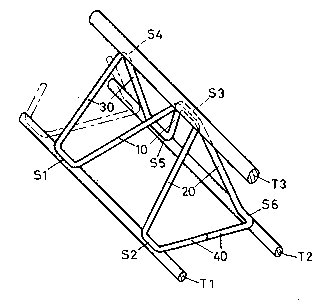
ABSTRACT OF THE DISCLOSURE
Stiffening elements are welded between the three
rods (T1, T2, T3) of three rod girders in underground
drift construction. Such stiffening elements consists
of three triangular wire polygons (10, 20, 30) connected
to form one piece. Two of the polygons meet at the top
rod (T3) to form a wire pyramid. The third wire polygon
(30) is perpendicular to the plane determined by the
axes of the lower rods (T1, T2). Since neither this
third wire polygon (30) nor the adjacent polygon (10),
which is one side of the pyramid, needs a cross-strut
between the lower rods (T1, T2), a significant saving in
materials combined with higher resistance to bending is
achieved.

Revendications

Note : Les revendications sont présentées dans la langue officielle dans laquelle elles ont été soumises.


What is claimed is :
1. Stiffening element for three-rod girder for
underground shaft construction, said three-rod girder
comprising two base rods (T1, T2) and a top rod (T3),
each of said rods forming an edge of a triangular prism,
said stiffening element being constituted by three ele-
ments each forming a triangular wire polygon (10, 20, 30),
said elements being connected to form one piece, two of
said wire polygons (10, 20) forming the side edges of
a four-sided wire pyramid having a tip which is welded
to said top rod (T3) and lower points welded to said two
base rods (T1, T2), a third straight one (30) of said
wire polygons defining a plane which is perpendicular to
the three rods (T1, T2, T3), and only the wire polygon
(20) which is most remote from said straight polygon (30)
comprising a strut (40) connecting said two base rods
(T1, T2).
2. Element in accordance with patent claim 1,
wherein said three wire polygons (10, 20, 30) form a
single wire loop.
- 8 -

Description

Note : Les descriptions sont présentées dans la langue officielle dans laquelle elles ont été soumises.


X92
FIELD OF THE INVENTION
.. ..
The invention relates to a stiffening element for a
la-ttice girder.
BACKGROUND OF THE INVEMTION
_ _ _
In underground drift cons-truction, after pr~paratory
work, arch supports are built in for support of the roof;
these arch supports provide access and are set in concrete.
Increasing numbers of lattice girders in conjunction with
- shotcrete are used because, in contrast to I- or U-beams,
they eliminate shaded areas behind the girder and there- ----~
fore a more even layer of concrete is made possible. -
Such lattice girders are described in EP-B-73733, for~
example.
~; Statical evidence from such a lattice girder shows
the local cut magnetidues of the individual bars of the
girder based on the global cut magnitudes in the total
system. The distance between the stiffening elements
plays a determinative role in this.
The larger the distance chosen, the more adversely
the local loads affect the girder, i.e., the less favorable
the transverse loads, the bending moments in the bars, and
the compression and tensile loads become, which causes
increased stress on the material and can finally necessitate ~ -
larger lateral section dimensions, which is also unecono- `
mical.
- 2 -
', -
, ~ .

7~07~
Even more determinative, however, is the fact that
the greater the distance between the joints on the indi-
vidual bar of the frame girder, the more adversely this
distance affects the local buckling tendency of such bar.
To improve the load and stability capacities of a
lattice girder, the stiffening elements should ideally
be relatively close to each other, on the one hand, and
the individual rod of the lattice girder should be
supported centrally between the joints, on the other
hand, so that its buckling length is halved.
An improvement was achieved in an embodiment accord-
ing to GB-A-2.195.677, which proposed a connecting ele-
ment in the forme of a four-sided pyramid whose tip is
secured to the top rod and whose lower ends are connected
by cross-struts diagonally to the lower rods. It was
proposed that a separate triangularly formed intermediate
element be attached perpendicularly to the rods to
improve resistance to buckling for such a connecting
element. However, such an additional, triangular support
element bound to the rods and attached vertically between
the stiffening elements produces an accumulation of
closely adjacent welding joints.
This is by no means desirable, however, since
these closely adjacent welding joints may affect the
.
- 3 -
:: . . ~ . ~. .
:: .. : , :
~''': ' ' - , . ' -
.~ ~ . ..

72~3~
structure of the steel (and in the worst case may even
promote a dangerous martensite formation), which can cause
brittleness in the rods and can thereby place the load-
bearing capacity of the lattice girder in doubt. In
extreme cases the welding joints can hreak under heavy
loads, which leads to displacement of the stiffening
elements.
SUMMARY OF THE INVENTION
It is therefore the object of the invention to
create a simple, inexpensive stiffening element which
enables a reduction by half of the distance between joints
in the individual lattice girder rods. At the same time,
high inherent stability, i.e., lateral stability, against
bending as well as against buckling and torsion are
achieved by the pyramid forms of the stiffening elements.
The stiffening element can be made in one piece so
that it can be connected to the rods at relatively few
welding joints; this reduces brittleness in the material
caused by welding.
BRIEF DESCRIPTION OF T~E DRAWINGS .
An embodiment of the invention will now be
described by way of example with reference to the
accompanying drawings, wherein:
Figure 1 shows a prior art connecting element
corresponding to Fig. 3 of GB-A-2.195.677; and
-- 4
, , . ~ ,
:~. . , ~ . . .
,
: .~ : .
. "~ ,
: ~ .,

7~2~2
Figure 2 is a perspective view of the elements in
accordance with the invention.
DESCRIPTION OF PREFERRED EMBODIMENT
The connecting element in accordance with Figure 1
consists of two portions 1 ancl 2, essentially triangular
wire polygons, welded to the three rods, the top rod T3
and the two lower rods T1 and T2, respectively at three
welding locations S3, S5, S8 and S5, S6 and S7. The
;~ welding location S5 on the top rod T3 is shown as a single
welding location, although there could easily be two
welding locations if there is a greater distance between
the two wire polygons 1, 2. A further wire triangle 3 is
welded in the two areas A (shown in dot-dash lines) in
order to increase the stability of the lattice girder,
in addition to the polygons 1, 2. Thus, three welding
locations S1, S2, S3, or S6, S10, S11 are repeatedly
closely adjacent to each other so that undesirable
formation of martensite is promoted, as discussed
herein above.
According to the invention, as shown in Figure 2,
there are likewise two triangular wire polygons 10, 20,
`~ similar to those desoribed in the previous example,
which are welded to the top bar T3 at a common welding
~ location S3. However,while wire polygon 20 is provided
':'
' '
..
, ~ : : .
- :. . : .
~: . -:

~37'29~
with a strut 40 connecting the two lower rods Tl, T2, a
further triangular wire polygon 30 is attached to the
other polygon 10, but without a strut connecting the two
lower rods Tl, T2. The necessary strut between the lower
rods Tl, T2 is formed by the succeecling polygon, indicated
in dot-dash lines.
An obious significant advantage in producing the
lattice girder with the type of stiffening elements in
Figure 2 is that such a stiffening element can be produced
in one piece with one welding location 41, so that, in
contrast to the prior art structure shown in Figure 1,
it is unnecessary to stock three different elements.
Load trials on test girders of the known and the
new construction type have shown that, with support at
1.5 m distances and pressure between the connecting
elements according to Figure 1, a load of 44.4 kN
produced a deformation of 80 mm. With stiffening elements
according to the present invention, a load of 51.5 kN
produced deformation of 82 mm.
Similar measurements led to similar results, but
with the load over the welding location on the top rod,
namely 50.6 kN for a deformation of 80 mm in the case of
the prior art structure and 54.2 kN for a deformation of
81 mm in the case of the applicants' stiffening element.
~ .
.
. :::, : . . ' ~ . ..
.,
:,`' ' ~ ~: ;
: : .
:: ~

` ~)07~
This means that, for identical local requirements,
a top rod of only 26 or 28 mm need be used for a given
bending force, instead of a top rod of 30 mm. In addition
to this saving in materials, there is the savings in
materials for the stiffening element itself because two
connecting struts between the lower rods, namely, the
strut on wire polygon 1 and the strut of polygon 3
parallel to it, are no longer required. This saving in
materials, with lO ~ to 15 % greater stability, can play
a significant role in underground drift construction.
~,
: - 7 -
.. .. . .
,............... :.

Dessin représentatif
Une figure unique qui représente un dessin illustrant l'invention.
États administratifs

2024-08-01 : Dans le cadre de la transition vers les Brevets de nouvelle génération (BNG), la base de données sur les brevets canadiens (BDBC) contient désormais un Historique d'événement plus détaillé, qui reproduit le Journal des événements de notre nouvelle solution interne.

Veuillez noter que les événements débutant par « Inactive : » se réfèrent à des événements qui ne sont plus utilisés dans notre nouvelle solution interne.

Pour une meilleure compréhension de l'état de la demande ou brevet qui figure sur cette page, la rubrique Mise en garde , et les descriptions de Brevet , Historique d'événement , Taxes périodiques et Historique des paiements devraient être consultées.

Historique d'événement

Description Date
Inactive : CIB de MCD 2006-03-11
Inactive : Abandon.-RE+surtaxe impayées-Corr envoyée 1997-01-08
Inactive : Demande ad hoc documentée 1997-01-08
Demande non rétablie avant l'échéance 1994-07-09
Le délai pour l'annulation est expiré 1994-07-09
Réputée abandonnée - omission de répondre à un avis sur les taxes pour le maintien en état 1994-01-10
Inactive : Demande ad hoc documentée 1994-01-10
Demande publiée (accessible au public) 1990-08-01

Historique d'abandonnement

Date d'abandonnement Raison Date de rétablissement
1994-01-10
Titulaires au dossier

Les titulaires actuels et antérieures au dossier sont affichés en ordre alphabétique.

Titulaires actuels au dossier
PANTEX - STAHL AG.
Titulaires antérieures au dossier
HANS HUGI
PETER SALZMANN
Les propriétaires antérieurs qui ne figurent pas dans la liste des « Propriétaires au dossier » apparaîtront dans d'autres documents au dossier.
Documents

Pour visionner les fichiers sélectionnés, entrer le code reCAPTCHA :


Pour visualiser une image, cliquer sur un lien dans la colonne description du document. Pour télécharger l'image (les images), cliquer l'une ou plusieurs cases à cocher dans la première colonne et ensuite cliquer sur le bouton "Télécharger sélection en format PDF (archive Zip)" ou le bouton "Télécharger sélection (en un fichier PDF fusionné)".

Liste des documents de brevet publiés et non publiés sur la BDBC .

Si vous avez des difficultés à accéder au contenu, veuillez communiquer avec le Centre de services à la clientèle au 1-866-997-1936, ou envoyer un courriel au Centre de service à la clientèle de l'OPIC.


Description du
Document 
Date
(aaaa-mm-jj) 
Nombre de pages   Taille de l'image (Ko) 
Abrégé 1990-07-31 1 27
Revendications 1990-07-31 1 31
Dessins 1990-07-31 1 35
Description 1990-07-31 6 189
Dessin représentatif 1999-07-28 1 12
Taxes 1992-12-02 1 26
Taxes 1991-11-24 1 28