Sélection de la langue

Search

Sommaire du brevet 2007302 

Énoncé de désistement de responsabilité concernant l'information provenant de tiers

Une partie des informations de ce site Web a été fournie par des sources externes. Le gouvernement du Canada n'assume aucune responsabilité concernant la précision, l'actualité ou la fiabilité des informations fournies par les sources externes. Les utilisateurs qui désirent employer cette information devraient consulter directement la source des informations. Le contenu fourni par les sources externes n'est pas assujetti aux exigences sur les langues officielles, la protection des renseignements personnels et l'accessibilité.

Disponibilité de l'Abrégé et des Revendications

L'apparition de différences dans le texte et l'image des Revendications et de l'Abrégé dépend du moment auquel le document est publié. Les textes des Revendications et de l'Abrégé sont affichés :

  • lorsque la demande peut être examinée par le public;
  • lorsque le brevet est émis (délivrance).
(12) Brevet: (11) CA 2007302
(54) Titre français: RACCORD A BRIDE, A BOULONNER
(54) Titre anglais: BOLT-ON FLANGE
Statut: Durée expirée - au-delà du délai suivant l'octroi
Données bibliographiques
(51) Classification internationale des brevets (CIB):
  • F16L 39/00 (2006.01)
  • F16L 41/08 (2006.01)
(72) Inventeurs :
  • ADAMS, CHARLES L. (Etats-Unis d'Amérique)
(73) Titulaires :
  • PVI INDUSTRIES, INC.
(71) Demandeurs :
  • CHARLES L. ADAMS (Etats-Unis d'Amérique)
(74) Agent: GOWLING WLG (CANADA) LLP
(74) Co-agent:
(45) Délivré: 1997-01-28
(22) Date de dépôt: 1990-01-08
(41) Mise à la disponibilité du public: 1991-01-27
Requête d'examen: 1992-12-11
Licence disponible: S.O.
Cédé au domaine public: S.O.
(25) Langue des documents déposés: Anglais

Traité de coopération en matière de brevets (PCT): Non

(30) Données de priorité de la demande:
Numéro de la demande Pays / territoire Date
386,455 (Etats-Unis d'Amérique) 1989-07-27

Abrégés

Abrégé anglais


A bolt-on fitting is shown for coupling a fitting
to an object having external sidewalls and a normally
closed interior containing a liquid, such as a water
heater tank or boiler. The bolt-on fitting has a body
with an inner surface and an outer surface. A
plurality of bolt openings are spaced about the
periphery of the body. An O-ring is located on the
inner surface for sealing between the flange and the
mating surface on the tank. The inner surface of the
flange is concave, being curved about both a horizontal
and a vertical axis drawn to bisect the body so that
the bolt openings form isolated points of contact with
the tank surface when the flange is bolted into
position.

Revendications

Note : Les revendications sont présentées dans la langue officielle dans laquelle elles ont été soumises.


The embodiments of the invention in which an
exclusive property or privilege is claimed are defined
as follows:
1. A bolt-on flange for a water heater tank or
boiler of the type having cylindrical external
sidewalls provided with a plurality of outwardly
extending threaded bolts, and a nut for each bolt the
flange comprising:
a body having an inner surface adapted to be
supported at a selected location on the tank sidewalls
and an outer surface;
a plurality of bolt openings spaced about the
periphery of said body and communicating said inner and
outer surfaces, the spacing of said bolt openings being
selected to mate with the outwardly extending bolts on
said tank sidewalls;
an O-ring located on said inner surface for
sealing between said flange and said cylindrical
sidewalls when said flange is bolted in place;
retaining means for maintaining the position
of said O-ring on said inner surface; and
wherein said inner surface is concave, being
curved about both a horizontal and a vertical axis
drawn to bisect the body, thereby forming a spherical-
shaped void on said inner surface, said bolt openings
forming isolated points of contact with said tank
sidewalls when said flange is bolt into position by
tightening said nuts on said threaded bolts.
2. The bolt-on flange of claim 1, wherein said
retaining means is an O-ring groove located on said
inner surface of said body.
3. The bolt-on fitting of claim 2, wherein said
body has a central opening for receiving an associated
-10-

fitting, said central opening being located within the
periphery of said bolt-receiving openings.
4. The bolt-on fitting of claim 3, wherein said
O-ring groove and O-ring are located on said inner
surface between said central opening and said bolt-
receiving openings.
5. A method of installing a flange onto the
external sidewalls of a water heater tank or boiler
provided with a tank opening on the exterior thereof,
the method comprising the steps of:
welding a plurality of outwardly extending
threaded bolts onto the tank exterior about the
periphery of the tank opening;
providing a bolt-on flange with a body having
an inner surface and an outer surface, the inner
surface being provided with a plurality of bolt
openings spaced about the periphery of said body and
communicating said inner and outer surfaces, the inner
surface of the flange body being formed doubly concave,
being curved about both a horizontal and a vertical
axis drawn to bisect said body, thereby forming a
spherical-shaped void on said inner surface, said bolt
openings forming isolated points of contact with said
tank sidewalls when said flange is bolted into
position;
locating the flange on the tank exterior by
passing the outwardly extending bolts through the bolt
openings provided in the flange body;
sealing the flange to the tank exterior by
means of an O-ring located on said inner surface;
bolting the flange onto the tank by attaching
nuts to the threaded bolts and tightening said nuts
against said flange to force said flange against said
tank.
-11-

6. The method of claim 5, wherein said tank has
a domed top provided with a top opening and outwardly
extending bolts, and wherein a flange is bolted onto
the top opening in the same manner as the flange was
bolted to the tank sidewalls.
-12-

Description

Note : Les descriptions sont présentées dans la langue officielle dans laquelle elles ont été soumises.

2007302
BACKGROUND OF THE INVENTION
2 1. Fiel~l oftlle Invention.
4 This invention relates generally to an improved
flange for coupling various fittings to an object
6 having external sidewalls and a normally closed
7 interior containing a liquid and, specifically, to an
8 improved flange for coupling various fittings to a
9 water heater/boiler tank, piping or related plumbing
components.
11
12 2. I)escription oftlle ~'riorArt.
13
14 Water heaters and boilers include a tank which is
provided with a plurality of tank openings for
16 attaching pipes, heating elements and similar fittings
17 to the tank. For example, a typical water heater is
18 provided with an inlet valve, a drain valve, and an
19 ASME rated relief valve, among other fittings.
21 In the past, the tank opening or port typically
22 had a flange welded on for receiving the various tank
23 fittings. The excessive heat used in the welding
24 process often caused the flange to distort, leading to
sealing problems and premature failure in use. In
26 addition, the manufacturing steps involved in welding a
27 flange were time consuming and relatively expensive.
28
29 The present invention has as its object to provide
a bolt-on fitting for a tank opening of a water heater
31 or boiler, or a bolt-on fitting for other related
32 piping or plumbing components, such as a bolt-on
33 fitting for an opening provided in a transfer pipe
34 running to or from a water heater tank.

2007302
1 Another object of the invention is to provide such
2 a flange which is sealed by means of an O-ring seal
3 carried on an inner surface of the flange between the
4 flange and the mating surface of the object to which
the flange is attached.
7 Another object of the invention is to provide a
8 bolt-on flange with a double curved inner surface
9 adapted to mate with either a cylindrical sidewall or a
spherical surface.
11
12 Additional objects, features and advantages will
13 be apparent in the written description which follows.

2007302
SUMMARY OF THE INVENTION
3 The bolt-on flange of the invention is used for
4 coupling a fitting to an object having external
sidewalls and a normally closed interior containing a
6 liquid. For instance, the bolt-on fitting can be used
7 on a water heater tank or boiler of the type having
8 cylindrical external sidewalls. The bolt-on flange
9 includes a body having an inner surface which is
adapted to be supported at a selected location on the
11 tank sidewalls and has an outer surface. A plurality
12 of bolt openings are spaced about the periphery of the
13 body and communicate the inner and outer surfaces. An
14 O-ring is located on the inner surface for sealing
between the flange and the cylindrical sidewalls when
16 the flange is bolted in place. Retaining means are
17 provided for maintaining the position of the O-ring on
18 the inner surface. The inner surface is preferably
19 concave, being curved about both a horizontal and a
vertical axis drawn to bisect the body.
21
22 Preferably, the retaining means used to maintain
23 the position of the O-ring is an O-ring groove provided
24 on the inner surface of the flange body. The concave
inner surface of the flange body preferably forms a
26 spherical-shaped void on the inner surface, whereby the
27 bolt openings form isolated points of contact with the
28 tank sidewalls when the flange is bolted into position.

2007302
BRIEF DESCRIPTION OF THE DRAWINGS
3 Figure 1 is a simplified, perspective view of a
4 water heater showing a bolt-on flange of the invention
on the tank cylindrical sidewalls;
7 Figure 2 is a partial, cross-sectional view taken
8 along lines II-II in Figure l;
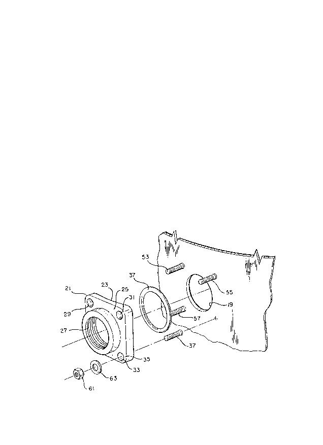
Figure 3 is an exploded view of the bolt-on flange
11 of Figure 1 showing the tank opening and a portion of
12 the tank cylindrical sidewalls;
13
14 Figure 4 is an isolated view of the domed top of
the tank of Figure 1 showing a bolt-on flange installed
16 thereon;
17
18 Figure 5 is a schematic view illustrating the
19 double curved inner surface of the flange fitting of
the invention;
21
22 Figure 6 is a top view of the bolt-on flange of
23 the invention;
24
Figure 7 is a side, cross-sectional view taken
26 along lines VII-VII in Figure 6; and
27
28 Figure 8 is a cross-sectional view taken along
29 lines VIII-VIII in Figure 6.

2(:~07302
DETAILED DESCRIPTION OF THE INVENTION
3 Figure 1 shows a water heater tank 11 having
4 cylindrical external sidewalls 13 and a domed top 15.
A flange 17 of the invention is shown installed on the
6 tank cylindrical sidewalls 13 about a tank opening 19.
7 The flange 17 could be equipped, for example, with a
8 two inch NPT opening used as a pipe coupling, or could
9 be designed to receive other fittings, such as an
electric heating element. Any type fitting can be
11 utilized with the flange of the invention were it is
12 desirable to connect a fitting to an object having
13 external sidewalls and a normally closed interior
14 containing a liquid. For instance, the flange could be
used to connect a fitting to an opening provided in a
16 transfer pipe (not shown) running to or from the tank
17 11.
18
19 As shown in Figures 2 and 3, the flange includes a
body 21 having an inner surface 23 adapted to be
21 supported at a selected location on the mating surface
22 of the object to which the flange is attached, in this
23 case the tank exterior surface 25. The flange shown in
24 Figure 3 has a central opening 27 which, in this case,
is a two inch NPT threaded opening for use as a pipe
26 coupling. The body 21 is generally square and includes
27 a plurality of bolt openings (29, 31, 33 shown). The
28 bolt openings are equidistantly spaced about the
29 periphery 35 of the body and communicate the inner and
outer surfaces 23, 25.
31
32 Sealing means, such as an O-ring 37 is located on
33 the inner surface 23 for sealing between the flange 17
34 and the tank sidewalls when the flange is bolted in

2Q07302
1 place. Retaining means are provided for maintaining
2 the position of the O-ring on the inner surface 23 to
3 prevent the O-ring from being squeezed out beneath the
4 peripheral edges of the flange. Preferably, the
retaining means is an O-ring groove 39 which is located
6 between the bolt openings 29, 31, 33 and the central
7 opening 27.
9 As shown in Figures 2 and 5-8, the inner surface
23 of the body 21 is concave, being curved about both a
11 horizontal and a vertical axis 41, 43 (Figure 6),
12 respectively, drawn to bisect the body 21. In this
13 way, the inner surface 23 forms a spherical-shaped void
14 (see Figure 5) with the bolt openings 29, 31, 33, 34
forming isolated points of contact with the tank
16 exterior when the flange is bolted into position. The
17 doubly curved inner surfaces are illustrated as 45, 47
18 in Figures 7 and 8. The radius of curvature employed
19 for each curved inner surface (49 in Figure 2) is not
critical as long as the radius is the same as or
21 smaller than that of the mating surface to which the
22 flange is being attached, in this case, tank exterior
23 51. The radius of curvature for the doubly curved
24 surfaces 45, 47 (Figures 7 and 8) can be identical. As
long as the radius of curvature of the inner surface 23
26 is smaller than the radius of the tank external surface
27 which is to be fit, the flange will rest on 4 points
28 adjacent the bolt openings 29, 31, 33, 34. In this
29 way, when the nuts are tightened onto the bolts during
the flange installation, the flange will not be bent or
31 stressed.
32
33 A variety of commercially available O-rings can be
34 utilized in the practice of the invention. The O-ring

2007302
1 37 must be of a cross-sectional diameter that will have
2 at least a minimum compression when the four corners of
3 the flange touch the tank exterior in order to maintain
4 the seal. Otherwise, the O-ring dimensions or type of
materials are not critical.
7 In the method of installing a flange of the
8 invention, a plurality of outwardly extending bolts 53,
9 55, 57, 59 are first installed on the tank exterior
about the periphery of the tank opening 19, as by
11 welding. Preferably, the bolts are stud welded by
12 known resistance welding techniques so that the studs
13 fuse and penetrate into the steel of the tank sidewall.
14
The flange 17 is then located on the tank exterior
16 by passing the outwardly extending bolts 53, 55, 57, 59
17 through the bolt openings 29, 31, 33, 34 provided in
18 the flange body. The O-ring 37 is retained within the
19 O-ring groove 39 located on the inner surface 23 of the
flange body 21 during the assembly. A nut 61 and
21 associated washer 63 are then placed on each bolt and
22 threaded into position to securely seat the flange on
23 the tank exterior and complete the assembly.
24
As shown in Figure 4, the doubly curved inner
26 surface 23 allows an identical fitting to be secured to
27 the tank opening 65 provided in the domed top 15.
28
29 An invention has been provided with several
advantages. Because the flange of the invention can be
31 bolted-on, the flange is not distorted by heat
32 associated with prior art welding techniques. The
33 positioning bolts can be stud welded in a matter of
34 seconds to the tank exterior and the flange can

2007302
1 thereafter be bolted-on much more quickly than the
2 welding steps involved in welding the prior art flange
3 to the tank exterior. Because of the curvature of the
4 inner surface of the flange body, the flange sits on
its four peripheral corners forming a compression seal
6 between the internal O-ring and the tank exterior.
7 There is no tendency to bend or flatten the flange as
8 would happen if the inner surface were flat. The
g flange fitting can be economically produced from a
variety of materials and by a variety of techniques.
11 For instance, the flange can be stamped or cast from
12 steel, bronze, cast iron, and the like.
13
14 While the invention has been shown in only one of
its forms, it is not thus limited but is susceptible to
16 various changes and modification without departing from
17 the spirit thereof.

Dessin représentatif
Une figure unique qui représente un dessin illustrant l'invention.
États administratifs

2024-08-01 : Dans le cadre de la transition vers les Brevets de nouvelle génération (BNG), la base de données sur les brevets canadiens (BDBC) contient désormais un Historique d'événement plus détaillé, qui reproduit le Journal des événements de notre nouvelle solution interne.

Veuillez noter que les événements débutant par « Inactive : » se réfèrent à des événements qui ne sont plus utilisés dans notre nouvelle solution interne.

Pour une meilleure compréhension de l'état de la demande ou brevet qui figure sur cette page, la rubrique Mise en garde , et les descriptions de Brevet , Historique d'événement , Taxes périodiques et Historique des paiements devraient être consultées.

Historique d'événement

Description Date
Inactive : Périmé (brevet - nouvelle loi) 2010-01-08
Inactive : Lettre officielle 2006-09-15
Inactive : Paiement correctif - art.78.6 Loi 2006-08-22
Inactive : CIB de MCD 2006-03-11
Lettre envoyée 2001-02-21
Lettre envoyée 1997-12-15
Accordé par délivrance 1997-01-28
Exigences pour une requête d'examen - jugée conforme 1992-12-11
Toutes les exigences pour l'examen - jugée conforme 1992-12-11
Demande publiée (accessible au public) 1991-01-27

Historique d'abandonnement

Il n'y a pas d'historique d'abandonnement

Taxes périodiques

Le dernier paiement a été reçu le 

Avis : Si le paiement en totalité n'a pas été reçu au plus tard à la date indiquée, une taxe supplémentaire peut être imposée, soit une des taxes suivantes :

  • taxe de rétablissement ;
  • taxe pour paiement en souffrance ; ou
  • taxe additionnelle pour le renversement d'une péremption réputée.

Veuillez vous référer à la page web des taxes sur les brevets de l'OPIC pour voir tous les montants actuels des taxes.

Historique des taxes

Type de taxes Anniversaire Échéance Date payée
Enregistrement d'un document 1997-06-17
TM (brevet, 8e anniv.) - générale 1998-01-20 1997-10-29
TM (brevet, 9e anniv.) - générale 1999-01-08 1998-11-06
TM (brevet, 10e anniv.) - générale 2000-01-10 1999-10-18
TM (brevet, 11e anniv.) - générale 2001-01-08 2000-11-06
Enregistrement d'un document 2001-01-02
TM (brevet, 12e anniv.) - générale 2002-01-08 2001-10-23
TM (brevet, 13e anniv.) - générale 2003-01-08 2002-12-24
TM (brevet, 14e anniv.) - générale 2004-01-08 2003-11-24
TM (brevet, 15e anniv.) - générale 2005-01-10 2004-10-20
TM (brevet, 16e anniv.) - générale 2006-01-09 2005-10-25
2006-08-22
TM (brevet, 17e anniv.) - générale 2007-01-08 2006-10-23
TM (brevet, 18e anniv.) - générale 2008-01-08 2007-11-05
TM (brevet, 19e anniv.) - générale 2009-01-08 2008-10-29
TM (demande, 2e anniv.) - petite 02 1992-01-08
Titulaires au dossier

Les titulaires actuels et antérieures au dossier sont affichés en ordre alphabétique.

Titulaires actuels au dossier
PVI INDUSTRIES, INC.
Titulaires antérieures au dossier
CHARLES L. ADAMS
Les propriétaires antérieurs qui ne figurent pas dans la liste des « Propriétaires au dossier » apparaîtront dans d'autres documents au dossier.
Documents

Pour visionner les fichiers sélectionnés, entrer le code reCAPTCHA :


Pour visualiser une image, cliquer sur un lien dans la colonne description du document. Pour télécharger l'image (les images), cliquer l'une ou plusieurs cases à cocher dans la première colonne et ensuite cliquer sur le bouton "Télécharger sélection en format PDF (archive Zip)" ou le bouton "Télécharger sélection (en un fichier PDF fusionné)".

Liste des documents de brevet publiés et non publiés sur la BDBC .

Si vous avez des difficultés à accéder au contenu, veuillez communiquer avec le Centre de services à la clientèle au 1-866-997-1936, ou envoyer un courriel au Centre de service à la clientèle de l'OPIC.


Description du
Document 
Date
(aaaa-mm-jj) 
Nombre de pages   Taille de l'image (Ko) 
Page couverture 1993-12-04 1 14
Revendications 1993-12-04 9 124
Abrégé 1993-12-04 1 21
Description 1993-12-04 8 266
Dessins 1993-12-04 2 55
Page couverture 1997-01-28 1 14
Abrégé 1997-01-28 1 22
Description 1997-01-28 8 267
Revendications 1997-01-28 3 87
Dessins 1997-01-28 2 56
Dessin représentatif 1999-07-15 1 15
Taxes 2002-12-24 1 29
Taxes 2003-11-24 1 29
Taxes 1998-11-06 1 31
Taxes 2001-10-23 1 28
Taxes 1997-10-29 1 31
Taxes 1999-10-18 1 26
Taxes 2000-11-06 1 29
Taxes 2004-10-20 1 30
Taxes 2005-10-25 1 36
Correspondance 2006-09-15 1 15
Taxes 2006-10-23 1 27
Taxes 2007-11-05 1 29
Taxes 2008-10-29 1 31
Taxes 1996-11-13 1 30
Taxes 1995-10-26 1 35
Taxes 1994-10-19 1 46
Taxes 1993-10-21 1 36
Taxes 1992-10-27 1 35
Taxes 1991-11-01 1 30
Demande de l'examinateur 1996-05-17 2 96
Correspondance de la poursuite 1996-08-19 2 80
Correspondance de la poursuite 1993-03-11 1 26
Correspondance reliée au PCT 1996-11-21 1 33
Correspondance reliée au PCT 1993-11-17 1 36
Courtoisie - Lettre du bureau 1993-01-15 1 43
Correspondance de la poursuite 1992-12-11 1 29