Sélection de la langue

Search

Sommaire du brevet 2007406 

Énoncé de désistement de responsabilité concernant l'information provenant de tiers

Une partie des informations de ce site Web a été fournie par des sources externes. Le gouvernement du Canada n'assume aucune responsabilité concernant la précision, l'actualité ou la fiabilité des informations fournies par les sources externes. Les utilisateurs qui désirent employer cette information devraient consulter directement la source des informations. Le contenu fourni par les sources externes n'est pas assujetti aux exigences sur les langues officielles, la protection des renseignements personnels et l'accessibilité.

Disponibilité de l'Abrégé et des Revendications

L'apparition de différences dans le texte et l'image des Revendications et de l'Abrégé dépend du moment auquel le document est publié. Les textes des Revendications et de l'Abrégé sont affichés :

  • lorsque la demande peut être examinée par le public;
  • lorsque le brevet est émis (délivrance).
(12) Brevet: (11) CA 2007406
(54) Titre français: DESHYDRATEUR D'AIR AUTONOME
(54) Titre anglais: IMPROVED SELF-CONTAINED AIR DRYING UNIT
Statut: Périmé et au-delà du délai pour l’annulation
Données bibliographiques
(51) Classification internationale des brevets (CIB):
  • F24F 3/14 (2006.01)
  • B01D 53/26 (2006.01)
(72) Inventeurs :
  • FRESCH, VINCENT P. (Etats-Unis d'Amérique)
  • MATHEWS, TITUS (Etats-Unis d'Amérique)
  • ROSSI, ANTHONY R. (Etats-Unis d'Amérique)
(73) Titulaires :
  • PNEUMATECH, INC.
(71) Demandeurs :
  • PNEUMATECH, INC. (Etats-Unis d'Amérique)
(74) Agent: RICHES, MCKENZIE & HERBERT LLP
(74) Co-agent:
(45) Délivré: 2000-07-25
(22) Date de dépôt: 1990-01-09
(41) Mise à la disponibilité du public: 1990-07-10
Requête d'examen: 1997-01-06
Licence disponible: S.O.
Cédé au domaine public: S.O.
(25) Langue des documents déposés: Anglais

Traité de coopération en matière de brevets (PCT): Non

(30) Données de priorité de la demande:
Numéro de la demande Pays / territoire Date
07/295,482 (Etats-Unis d'Amérique) 1989-01-10

Abrégés

Abrégé anglais


An improved self-contained air drying unit
utilizes a single fan to draw air across an
aftercooler, a condenser and a reheater, all of which
are located within a single housing.

Revendications

Note : Les revendications sont présentées dans la langue officielle dans laquelle elles ont été soumises.


Various modes of carrying out the invention
are contemplated as being within the scope of the
following claims, particularly pointing out and
distinctly claiming the subject matter which is
regarded as the invention.
WE CLAIM:
1. An improved self-contained air drying
unit of the type in which heated air from a compressor
is introduced into the unit and cooled and dried in a
heat exchanging evaporator which has been supplied with
liquid refrigerant, wherein the improvement comprises:
aftercooler means disposed within the unit
for reducing the temperature of the air prior to its
introduction into the heat exchanging evaporator,
condenser means disposed within the unit and
substantially adjacent said aftercooler means for
cooling the compressed refrigerant gas and producing
liquid refrigerant, and
air circulating means disposed within the
unit for drawing ambient air across both of said
aftercooler means and said condenser means.
2. The improved self-contained air drying
unit defined in claim 1 wherein said air, circulating
means comprises a fan disposed in an upper portion of
the unit and drawing ambient air upwardly across said
aftercooler means and said condenser means which are
disposed below said fan.
3. The improved self-contained air drying
unit defined in claim 1 further comprising reheating
moans for raising the temperature of the air exiting
the heat exchanging evaporator with said reheating
means disposed within the unit and substantially
adjacent said aftercooler means and said condenser
means so that said air circulating means also draws air
across said reheating means.
-5-

4. The improved self-contained air drying
unit defined in claim 3 wherein said repeating means is
disposed up-stream from said aftercooler means and said
condenser means so that ambient air is drawn across
said repeating means prior to encountering said
aftercooler means and said condenser means.
5. An improved self-contained air drying
unit of the type in which heated air from a compressor
is introduced into the unit and cooled and dried in a
heat exchanging evaporator which has been supplied with
liquid refrigerant, wherein the improvement comprises:
aftercooler means disposed within the unit
for reducing the temperature of the air prior to its
introduction into the heat exchanging evaporator,
condenser means disposed within the unit and
substantially adjacent said aftercooler means for
cooling the compressed refrigerant gas and producing
liquid refrigerant, and
a fan disposed in an upper portion of the
unit and drawing ambient air upwardly across said
aftercooler means and said condenser means which are
disposed below said fan.
6. The improved self-contained air drying
unit defined in claim 5 further comprising repeating
means for raising the temperature of the air exiting
the heat exchanging evaporator with said repeating
means disposed within the unit and substantially
adjacent said aftercooler means and said condenser
means so that said fan also draws air across said
repeating means.
7. The improved self-contained air drying
unit defined in claim 6 wherein said repeating means is
disposed up-stream from said aftercooler means and said
condenser means so that ambient air is drawn across
said repeating means prior to encountering said
aftercooler means and said condenser means.
-6-

Description

Note : Les descriptions sont présentées dans la langue officielle dans laquelle elles ont été soumises.

TMPROVED SELF-CONTAINED AIR DRYING UNIT
~ackgro_und of the Invention
The present invention relates to an apparatus
for drying air and more specifically to a self-
contained air drying unit in which all the operational
components typical of an air drying system are located
and contained within a single unit.
Many industrial applications require the use
of extremely clean-and dry~~air~em~y~.K~Pne~uma~tic.l~tools,
robotics and ~paimE~'spray~rs~~are but three of the many
instances in which industry requires extremely dry air
far use in a compressed air system.
While ~~~'"f~~~~~dryingy~systems are available for
industrial use, the typical industrial systems are
1S extremely large and expensive and do not lend
themselves to small shop applications.
The small air drying equipment that is
available utilizes a number of components that are
separately packaged and must be interconnected in order
to provide an operable system.
It is the object of the present invention to
provide a small, compact air drying unit in which all
the necessary components are located within a single
cabinet.
2S Summar~of the Tnvention
An improved self-contained air drying unit of
the type in which heated air from a compressor is
cooled and dryed in a heat exchanging evaporator
includes an aftercooler disposed within the unit for
reducing the temperature of the air prior to its
introduction into the heat exchanging evaporator.
In accordance with another aspect of the
invention the unit is provided with a condenser
disposed substantially adjacent the aftercooler for
-1-

cooling the compressed refrigerant gas and producing
liquid refrigerant.
In accordance with yet another aspect of the
invention, the unit is grovided with a fan that is
disposed within the unit and which draws ambient air
across both the aftercooler and the condenser.
In accordance with still another aspect of
the invention, the air drying unit is provided with a
reheater for raising the temperature of the air exiting
the heat exchanging evaporator and the reheater is
located substantially adjacent to the aftercooler and
the condenser so that the single fan can draw air
across all three components.
The present invention thus provides a
compact, inexpensive air drying unit in which all the
operational companents are located within a single
cabinet.
Brief Description of the Drawings
The drawings illustrate the best mode
presently contemplated of carrying out the invention.
In the drawings:
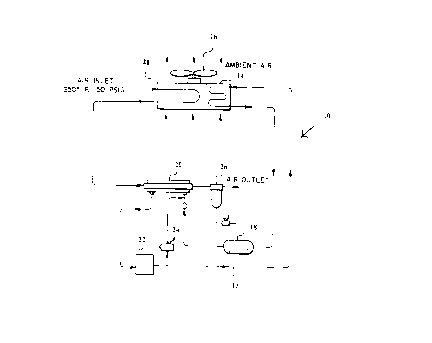
FIGURE 1 is a schematic representation of an
improved self-contained air drying unit constructed
according to the present invention; and
FIGURE 2 is a schematic representation of an '
alternate embodiment of the air drying unit of FIGURE
1.
Des_criptian of the Preferred Embodiment
As shown in FIGURE 1 an improved self-
contained air drying unit 10 receives compressed and
heated air ~rom an air compresses (not shown) via an
air inlet 12. Air inlet 12 is located on the exterior
of a cabinet (not shown) which contains all of the
working components described hereafter.
-2-

._.~. n ~.n
The compressed hot air is introduced into an
aftercooler 14 which consists of a serpentine length of
copper tubing across which ambient air is drawn by
means of fan 16. The compressed hot air exits
aftercooler 14 at a temperature within approximately 10
to 15 degrees of the ambient temperature. This pre-
cooled air is then introduced into heat exchanging
evaporator 18. Evaporator 18 is provided with liquid
refrigerant that is supplied by condenser 20 and
ZO proceeds through a filter dryer-22 and a metering
device 24. Filter dryer 22 may be of the type marketed
by Midwest Component under Model No. RTR-lOX and
metering device 24 may be of the,type marketed by J. B.
Industries under Model No. TC-50--100. The liquid
refrigerant is allowed to evaporate in evaporator 18
thus reducing the temperature of the air within it.
Cold dry air exits the evaporator at approximately 38
degrees fahrenheit and the condensed moisture in the
air is separated at separator 26 and dry air exits the
unit at air outlet 28 on the exterior of the cabinet.
Separator 26 may be of the type marketed by Parker
under Model No. 07F3B00012.
As is typical with systems of this type the
evaporated refrigerant gas is removed from the
evaporator 18 and introduced to a compressor 30 such as
an Aspera-GPD LTD Model No. E6170A. The compressed
refrigerant gas is them transferred to condenser 20
where it is cooled so as to provide liquid
refrigerant. Condenser 20 is located substantially
adjacent aftercooler 14 so that a single fan 16 can be
utilized to draw ambient air across both aftercooler 14
and condenser 20.
The system is also provided with a hot gas
bypass valve 32 such as a Sporlan Model No. AJE 1-1/4
which will divert a portion of the compressed hot
-3-

refrigerant gas to the evaporator to avoid a freezing
condition within the evaporator.
FIGURE 2 illustrates an improved self°
contained air drying unit of the type similar to that
shown in FIGURE 1, but with the addition of a repeater
34. Tn some instances it is necessary to heat the dry
air exiting evaporator 18 and thus, unit 10 shown on
FIGURE 2 is provided with repeater 34 located
substantially adjacent and below aftercooler 14 and
condenser 20. Air enters the repeater at approximately
38 degrees fahrenheit and fan 16 draws ambient air
across the repeater coils so that the air exiting
repeater 34 is at a temperature of approximately 68
degrees fahrenheit. The location of repeater 34
adjacent and below aftercooler 14 and condenser 20 is
particularly advantageous in that ambient air drawn
across these units by fan 16 will first encounter
repeater 34, cooling the ambient air, and this cooled
ambient air will then encounter aftercooler 14 and
condenser 20. Thus, a single fan 16 may be used to
provide all of the circulating air needed whether it be
for heating or cooling.
_4_

Dessin représentatif
Une figure unique qui représente un dessin illustrant l'invention.
États administratifs

2024-08-01 : Dans le cadre de la transition vers les Brevets de nouvelle génération (BNG), la base de données sur les brevets canadiens (BDBC) contient désormais un Historique d'événement plus détaillé, qui reproduit le Journal des événements de notre nouvelle solution interne.

Veuillez noter que les événements débutant par « Inactive : » se réfèrent à des événements qui ne sont plus utilisés dans notre nouvelle solution interne.

Pour une meilleure compréhension de l'état de la demande ou brevet qui figure sur cette page, la rubrique Mise en garde , et les descriptions de Brevet , Historique d'événement , Taxes périodiques et Historique des paiements devraient être consultées.

Historique d'événement

Description Date
Inactive : CIB de MCD 2006-03-11
Le délai pour l'annulation est expiré 2002-01-09
Lettre envoyée 2001-01-09
Accordé par délivrance 2000-07-25
Inactive : Page couverture publiée 2000-07-24
Préoctroi 2000-04-27
Inactive : Taxe finale reçue 2000-04-27
Inactive : Grandeur de l'entité changée 2000-03-28
Requête d'examen reçue 2000-03-16
Lettre envoyée 1999-11-01
Un avis d'acceptation est envoyé 1999-11-01
Inactive : Approuvée aux fins d'acceptation (AFA) 1999-10-12
Modification reçue - modification volontaire 1999-08-25
Inactive : Dem. de l'examinateur par.30(2) Règles 1999-04-28
Inactive : Dem. traitée sur TS dès date d'ent. journal 1998-07-31
Inactive : Renseign. sur l'état - Complets dès date d'ent. journ. 1998-07-31
Toutes les exigences pour l'examen - jugée conforme 1997-01-06
Exigences pour une requête d'examen - jugée conforme 1997-01-06
Demande publiée (accessible au public) 1990-07-10

Historique d'abandonnement

Il n'y a pas d'historique d'abandonnement

Taxes périodiques

Le dernier paiement a été reçu le 1999-12-21

Avis : Si le paiement en totalité n'a pas été reçu au plus tard à la date indiquée, une taxe supplémentaire peut être imposée, soit une des taxes suivantes :

  • taxe de rétablissement ;
  • taxe pour paiement en souffrance ; ou
  • taxe additionnelle pour le renversement d'une péremption réputée.

Veuillez vous référer à la page web des taxes sur les brevets de l'OPIC pour voir tous les montants actuels des taxes.

Historique des taxes

Type de taxes Anniversaire Échéance Date payée
Requête d'examen - petite 1997-01-06
TM (demande, 8e anniv.) - générale 08 1998-01-20 1997-12-24
TM (demande, 9e anniv.) - générale 09 1999-01-11 1999-01-04
TM (demande, 10e anniv.) - générale 10 2000-01-10 1999-12-21
2000-03-16
Taxe finale - générale 2000-04-27
Titulaires au dossier

Les titulaires actuels et antérieures au dossier sont affichés en ordre alphabétique.

Titulaires actuels au dossier
PNEUMATECH, INC.
Titulaires antérieures au dossier
ANTHONY R. ROSSI
TITUS MATHEWS
VINCENT P. FRESCH
Les propriétaires antérieurs qui ne figurent pas dans la liste des « Propriétaires au dossier » apparaîtront dans d'autres documents au dossier.
Documents

Pour visionner les fichiers sélectionnés, entrer le code reCAPTCHA :


Pour visualiser une image, cliquer sur un lien dans la colonne description du document. Pour télécharger l'image (les images), cliquer l'une ou plusieurs cases à cocher dans la première colonne et ensuite cliquer sur le bouton "Télécharger sélection en format PDF (archive Zip)" ou le bouton "Télécharger sélection (en un fichier PDF fusionné)".

Liste des documents de brevet publiés et non publiés sur la BDBC .

Si vous avez des difficultés à accéder au contenu, veuillez communiquer avec le Centre de services à la clientèle au 1-866-997-1936, ou envoyer un courriel au Centre de service à la clientèle de l'OPIC.


Description du
Document 
Date
(aaaa-mm-jj) 
Nombre de pages   Taille de l'image (Ko) 
Page couverture 1993-12-13 1 18
Dessins 1993-12-13 1 16
Abrégé 1993-12-13 1 6
Revendications 1993-12-13 2 81
Description 1993-12-13 4 150
Page couverture 2000-06-30 1 21
Dessins 1999-08-25 1 18
Dessin représentatif 1999-07-27 1 7
Dessin représentatif 2000-06-30 1 5
Avis du commissaire - Demande jugée acceptable 1999-11-01 1 164
Avis concernant la taxe de maintien 2001-02-06 1 176
Correspondance 2000-04-27 1 36
Taxes 1999-01-04 1 43
Taxes 1997-12-24 1 46
Taxes 2000-03-16 1 55
Taxes 1999-12-21 1 39
Taxes 1996-12-13 1 43
Taxes 1995-12-21 1 47
Taxes 1994-12-21 1 41
Taxes 1993-12-14 1 33
Taxes 1992-12-18 1 34
Taxes 1991-12-16 1 32