Note : Les descriptions sont présentées dans la langue officielle dans laquelle elles ont été soumises.
z()~s~
BUBBLER VALVE
!
Back~round of the In ention
This application rela~es ~o the art of valves and,
more particularly, to valves of the typ~ that are pr~ssure
i~balanced in the closed direction. ~he invention i~
particularly applicable for use in bubbler valves for drinXing
fountains and will be described with ~pecific reference
thereto. However, it will be appreciated that the invention
has broader aspects and can be used for controlling ~low of
liquids in other environments.
Excessive water line pressure can caus~ a water stream
~rom a bubbler valve on a drinking ~ountain to over~hoot the
drain pan and cause damage. I~ would be desirable to have a
! bubbler valve that would maintain a substantially uniform flow
of water over a wide range Or inlet pressures.
Summary o~ the Invention
A valve has ~ poppet biased toward a closed position
by inlet pressure. A yieldable biasing spring ~electiv~ly
biases the poppet to an open position against the force o~
inlet pressure. The balance b~tween the yieldable spring and
inlet pressure adjusts the open position of the poppet to
regulate flow.
~'3(~7~5
In ~ pre~erred arrangemerlt, the valvQ o~ the pre~ent
application ~ncludes ~ pre~aur~ chamber bstween ~ nlet and
outlet port~. Pressure respc:nsive means within the pre~sure
chamber is r~sponsive to pressure therein for adjusting the
S open position of the poppet.
The pressure responsive means in the pres~ure chamber
may comprise a piston and flexible diaphragm connected with the
poppet.
The poppet extends through the valve inlet port and
has an enlarged ~rusto-conical end portion facing toward a 6eat
on the inlet pressure side of the inlet port.
It is a principal object of the present invention to
provide an improved valve that is pressure imbalanced in a
closed diraction.
It is another object of the invention to provide a
valve that will remain closed when su~jected to excessive inlet
pressure, and that will perform thi6 function without being
limited by ~he ~orce Or a closlng spr~ng.
It is al~o an obiect of the invention to provlde a
valve that is capable of malntaining sub6tanti~11y uni~orm ~low
over ~ w$de range cf inlet pressures.
- It i6 a ~urther object o~ the inventlon to provlde ~n
improved piston and diaphragm arrangement ~or such a valv~.
It is an additional ob;ect of the inventlon to provide
2S such a valve having an improved poppet seat at an inlet port.
8rie~ De~crl~ion e~ th~ Dr~win~
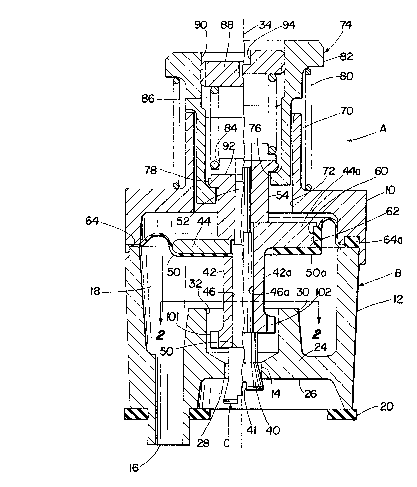
Figur~ crua~-s~cti~Al ~l~v~tloA~ w ~ ~
valve cons~ructed in ~ccordanc~ wlth ~he present appllcatlon;
and
Figure 2 is a partial cross-sectional elevational view
taken generally on line 2-2 of Figure 1.
Description of Preferred Embodiments
~ eferring now to ~he drawing, wherein the showing~ are
for purposes of illustrating certain preferred embodiments of
the invention only and not for purpo6es of limiking ~ame,
Figure 1 shows a valve A having a plastic housing ~ de~ined by
assembled upper and lower plastic housing parts 10, 12.
Inlet and outlet ports 14, 16 are provided in housing
B, and an internal pressure chamber 18 is provided between such
ports.
A gasket 20 is provided for mounting valve A in a
known manner with inlet port 14 connected to a pressurized
water ource, while outlet port 16 i5 connected to the outlet
of a bubbler on a drinking ~ountain.
~0 Inlet port 14 comprises a generally cylindrical hole
through a wall 24 of housing B, and having an inlet pressure
side 26 intersected by inlet por~ 1~ at ~ relatively sharp
circular edge 28. An annular guide ~le¢ve 30 exte~ds upwardly
~ 3~75~i
fro~ housing wall 24 in outwardly-~paced relationship to inlet
port 1~ and has an inner cylindrical bore 32 therein.
The movable components of valve A are shown in a valve
closed position on the right side of center line 34 and in a
valve open position on the left side of center line 34. In
addition, two different embodiments o~ a piston and diaphragm
a~6embly are shown on the opposite side~ of center line 34O
Movable poppet means C in the form o~ an elongated
poppet member extends upwardly through inlet port 14. ~n
enlarged head 40 on the bottom end portion of poppet C has an
external frusto-conical surface facing toward seat 28. A screw
driver 61Ot 41 is provided in the bottom end of poppet C to
facilitate assembly.
On the left side of center line 34 there i~ shown a
sleeve member 42 that i6 separate from piston 44. on the right
side of center line 34, aleeve member 42a i8 integral with
piston 44a. Poppet C extends through a central hole 46, 46a in
sleeve member 42, 42a, and h~s a ~houlder 50 engaging the
bottom and o~ sleeve member 42, 42a. Poppet C 0xtend~ upwardly
through centrAl hole~ in dlaphrag~ 50, soa ~nd 1~ pl~ton 44,
44a. A threaded upper ~nd portion 52 on poppet C i~ thre~ded
into a tapped hole in a retainer 54.
On the left of center line 34, an inner peripheral
portion of diaphragm 50 is trapped between the upper end of
sleeve member 42 and piston 44. The inner peripheral portion
Zn~)7565
- of di~phragm 50 is irmly clamped be~ween th~ upp~r end of
sleev~ member 4~ and piston 44 by all of these parts being
compressed between poppet shoulder ~0 and retainer member 54.
on the right 6ide of center line 34, ~leeve member 42a
and integral piston 44a are simply gripped between poppet
Rhoulder 50 and retainer member 54 to connect same to poppet
C. Piston 44a has a circumferential groove 60 in the outer
periphery thereof closely receiving an inwardly extending
circumferential pro~ection 62 on diaphragm 50a. The central
portion of diaphragm 50a i~ of generally cup-like configuration
and the dlameter of the inner sur~ace o~ diaphragm ~ro~ectlon
62 is somewhat smaller than the diameter o~ ths botto~ o~
recess 60. TherQfore, the central cup~ a portion o~
dlaphragm 50a i. ~tretched and gripplngly engage~ pi~ton 44a to
rQtain the diaphragm and pi~ton as~embled. Obv~ously, adhQslve
could be provided in reeess 60 for bonding diaphra~m projection
62 therein if 80 de~ired. A diaphragm outer peripheral portion
64, 64a is compressively gripped between housing parts 10, 12
which are welded or otherwise suitably secured together.
A button actuator guide sleeve 70 extends upwardly
from housing part 10 and has a central cylindrical hole 72
therethrough. An actuator button 74 is received in hole 7~ and
has an inwardly extending flange 76 engageable with an
outwardly extending flange 78 on retainer member 54. First
biasing means defined by a coil spring 80 acts on actuator
)7S~
button 74 to normally biaY poppet c closed a~ 3hown on the
right sid~ of cen~er line 3~ with the frusto-conical end
portion 4~ of poppet C engaging seat ~8~ Coil spring 80
~urround~ guide 61eeve 70 and ~cts between ~n upper surface of
housing part 10 an~ an outwar~ly extending flange 82 on
actuator bu~ton 74.
The upper end portion o~ ret~iner member 54 has an
outer circumferential recess 84 therein receiving one end
portion of a coil spring 86 defining second biasing ~eans. ~he
opposite end portion o~ spring 86 acts against the bottom
sur~ace of an adjustable stop member 88 threaded into a tapped
hole 90 in actuator button 74. The upper end portion of
retainer member 54 ha~ a ~crew driver ~lot therain, th~ botto~
of which is shown at 92 in Figure 1. ~d~ustable etop membQr 94
also has a ~crew driver ~lot 94 ther~in.
Sleeve member 42~ 42a has outwardly extending gulde
pro~ ~CtionB 101, 102 ~nd 103 th~roon 0108~1y received withln
cylindrical bore 32 in guide sleeve 30. This guides mov~ent
of poppet C between its open and closed positions, and
maintains the center line of poppet C coincidental with the
center of inlet port 14.
The parts are normally positioned as shown to the
right of center lina 34, with ~irst yieldable biasing means 80
biasing actuator button 74 upwardly to pull poppet C to its
closed position. Manual pushing force applied to button 74
S6~
will move same downwardly to the posltion 6hown on the left
side of cen~er line 34 and thls relleves the force o~ ~irst
yieldable biasing means 80 acting on poppet C. Thi~ allows
second yieldable biasing means ~6 to bias poppet C to its open
position shown on the left of center line 34. Inlet pressure
acting on the bottom end of poppet C tends to ~ove poppet C to
its closed position agains~ the biasing ~orce of second
yieldable biasing mean~ 86. The balance between the hiasing
force of second yieldable biasin~ means 86 and the inlet
pressure will adjust the open position of poppet C to maintain
a regulated flow through outlet port 16. In the event
excessive pressure builds up within pressure cha~ber 18, such
pressure acts on piston 44, 44a and diaphragm 50, 50a to move
poppet C toward its closed position to further adjust the flow
through inlet port 14 for maintaining a ~ubstantially unifo~m
flow through outlet port 16. Inlet pressure acting on the end
o~ popp~t c and on piaton 44, 44a against the bl~slng ~orc~ o~
spring 86 adjusts the relative open position of popp~t C for
maintaining a 6ubstantially unlform flow through outlet port 16.
The piston and diaphragm arrangement wi~hin pr3~sure
chamber 18 de~ines a pressure responsive means connectQd with
poppat C and being responsive to a predetermined exce~sive
pressure i.n the pressure chamber for overcoming thQ biasing
force of spring 86 to adjust the poppet to a different open
position.
6 S
It is obvlous that many dl~erent arr~nga~ent~ ara
po~si~lQ dapending upo~ the ~lze of the vAlve and kh0 de~lred
flow rate therethrough. In one arrangement, the sprlng rata of
spring 86 and the taper on the frusto-conical end portion of
poppet C are matched to produce a flow of approximately 0.43
gallons per minute over a wide range of inlet pressures.
Outlet port 16 may ~hen be sized to produce ~uch a flow rat~
when pressure chamber 18 is at approximately 2~4 PSIG, Any
deviation in the pressure within pressure chamber 18 i5 sensed
10 by the pressure responsive means defin~d by the piston and
diaphragm to ~urther adjust the position of poppet C and
maintain a regulated flow of water through outlet port 16.
Housing B and poppet C are preferably molded o~ a
plastic material having sufficient compliance to provide a good
seal between seat 28 and the frusto-conical surface on poppet C
without requiring any rubber washers or the like. Many
different types of plastics are suitable including, but not
limited to, polyamides.
Although the invention has been shown and descri~ed
with respect to certain preferred embodiments, it is obvious
that equivalent alterations and modi~ications will occur ko
other3 ~killad in the art upon the readlng ~nd under~tanding o~
this specificatlon. The present invention include~ all ~uch
equivalent altar~tion~ and modl~ic~tion~, and 1~ llml~d only
by the scope of the claims.