Note : Les descriptions sont présentées dans la langue officielle dans laquelle elles ont été soumises.
COMPACT PULSING PUMP FOR
IRRIGATION HANDPIECE
FIELD OF THE INVENTION
This invention relates to a surgical irrigation hand--
piece and a pulsing pump thereEor.
BACKGROUND OF THE INVENTION
Mattchen U.S. Patent No. 4 583 531 discloses a hand
held, pulsating jet, lavage usable for surgical purposes.
A pressure air powered, reciprocating motor drives a reci-
procating irrigant liquid pump to produce a pulsed irrigant
liquid stream from the front of the baxrel of the gun-
shaped lavage. The motor is connected to a continuous
source of pressure air.
However, the Mattchen motor and pump are separate andseparable units, the pump unit being disposable and the
motor unit being not. More particularly, in Mattchen the
forward portion of the barrel hinges open for removal and
replacement of the pump unit, the irrigant liquid supply
tube and the pulsating irrigant liquid outlet tube. The
top front portion of the barrel is hinged at the bottom
front of the barrel, so as to tilt forwardly and allow
~3 ~ 7S
upward removal of the mentioned pump unit and liquid supply
and outlet tubes. The remainder of the apparatus~ which is
to be reused, comprises the motor unit and a relatively
complex pressure air control valving system which is
trigger operated to modulate the flow of pressure air to
the motor and thereby control the pulsed irrigant liquid
output flow indirectly. The construction complexity of the
handpiece as a whole would appear to make it economically
impossible to market as a disposable handpiece, and indeed
the teaching of ~attchen on the point is clear.
Accordingly, separate sterilizations of the pump unit, with
its liquid hoses, on the one hand, and on the other hand
the remainder of the handpiece, as well as the need to
assemble and disassemble the two appear to add further to
the cost and extra time required to use this system on an
on-going basis.
Smith U.S. Patent No. 4 278 078 (assigned to the
assignee of the present invention) is pressure air powered
and does provide a pulsing irrigant liquid outflow. How-
ever, the Smith unit is not in the handy form oE a pistol,
and is not a disposable tool. Further, irrigant liquid i5
supplied to the tool by gravity from an elevated storage
container and passes through the tool in a resiliently
compressible tube. A hammer reciprocated by an air motor
repetitively pinches and unpinches the resilient tube to
pulse the flow of irrigant li~uid therethrough. The
irrigant liquid pulses tend to have gradual, rather than
sharp, start and stop characteristics. The apparatus does
not "pump" from a liquid store located vertically below it.
Atkinson U.S. Patent No. 4 655 197 discloses a hand-
piece providing a pulsating liquid flow for lavage use.
E~owever, pulsed irrigant liquid is applied to the handpiece
from a remote pulsing source, in the form of a self-
standing console. Liquid pulses may thus tend to become
z¢~ s
-- 3 --
less sharp and well defined before they reach the hand-
piece.
Kovach U.S. Patent No. 3 561 433 discloses a hand-held
dental cleaning and massaging device. However, the Kovach
device is in the form of a wand whose base includes both a
small water reservoir providing the sole source of liquid
and a CO2 cartridge as the sole pressure gas supply. A
trigger button shifts the valve core to permit pressurized
water to flow from the outlet end of the wand. An undis-
closed type of liquid pulsing device, of extremely compact
size, joins the water outlet tube to the base portion of
the wand. The only specific suggestion of a pulsing device
given is that it may be a fluidic multivibrator or oscil-
lator. The water suppl~ is necessarily very s~all in
volume and the pressure of the pressure ~as is very high
(as high as 900 PSI). The reliability and repeatability of
the pulsing unit is unknown. The structure is relatively
complex for its limited capability. Disposability appears
neither to be taught nor economically feasible.
The objects and purposes of this invention include
provision of a pulsed surgical irrigation handpiece and a
self-contained motor/pump unit therefor, which apparatus is
intended to be disposable after use and not to be reusable,
which is producible as a sealed handpiece unit, which has a
streamlined exterior free of tubes except at the base of
the handle and at the forward end of the barrel, which is
capable of incorporating and controlling suction as well as
pulsed irrigant liquid, which has a self-contained
motor/pump cartridge capable of producing sharp irrigant
liquid pulses, which includes a "pop" pressure gas exhaust
feature contributing to a rapid irrigant liquid pulse fall
time, and which locates the motor/pump cartridge in the
handle of the pistol-shaped handpiece to distribute weight
2?~
between the handle and barrel of the handpiece and thereby
provide a well-balanced hand tool.
Other object and purposes of the invention will be
apparent to persons acquainted with apparatus of this
general type upon reading the following description and
inspecting the accompanying drawings.
SUMMARY OF THE INVENTION
A surgical irrigation handpiece comprises a housing
having a handle and a barrel extending forwardly from the
handle. A pulsing pump is disposed in the handle and has
an outlet extending forward toward the front end of the
barrel for supplying pulsed irrigant liquid to a surgical
site.
A pressure gas powered, pulsed output, liquid pump
comprises a piston axially slidable in a casing, a poppit
axially slidable with respect to the piston for normally
blocking exhaust of pressure gas from the casing and spring
means associated with the piston and poppit.
BRIEF DESCRIPTION OF THE DRAWINGS
Figure 1 is a right side elevational view of a suryical
irrigation handpiece embodying the invention, with the
trigger pulled to permit maximum pulsed irrigant liquid
outflow.
Figure 2 is a central cross-sectional view of the
Figure 1 device showing alternate positions of the trigger
and thumb button in broken lines.
Figure 2A is an enlarged fragment of the Figure 2
trigger unit.
Figure 2B is a bottom view of the figure 2A trigger.
Figure 3 is a central cross-sectional view similar to
Figure 2 but with the pump/motor cartridge and suction tube
removed to show the interior wall of the left housing part
of the handpiece.
?~
Figure ~ is an enlarged central cross~sectional view of
the motor/pump cartridge of Figure 2.
Figure 4A is a top view of the Figure 4 upper flap
valve.
Figure 5 is an exploded pictorial view of the piston
and poppit assembly of the Figure 4 motor/pump cartridge.
Figure 6~ is a fragmentary central cross-sectional view
similar to Figure 5 but showing the piston in a forwardly
advanced position on its forward most limit.
Figure 6B is a view similar to Figure 6A with the
piston fully advanced forward and the poppit "poppedl' off
the pressure gas exhaust port to exhaust pressure gas from
the motor chamber.
Figure 7 is an exploded pictorial view of the Figure 1
handpiece.
Figure 8 is an enlarged exploded pictorial view of the
Figure 1 tip unit, omitting the barrel extension of Fiyure
9.
Figure 9 is an enlarged central cross-sectional view of
the Figure 1 tip extension mounted in the end of the hand-
piece barrel.
Figure 9A is a sectional view substantially as taken on
the line IXA-IXA of Figure 9.
Figure 10 is a sectional view substantially as taken on
the line X-X of Figure 9.
Figure 11 is a central cross-sectional view of an
exhaust gas muffler usable with the Figure 1 handpiece.
DETAILED DESCRIPTION
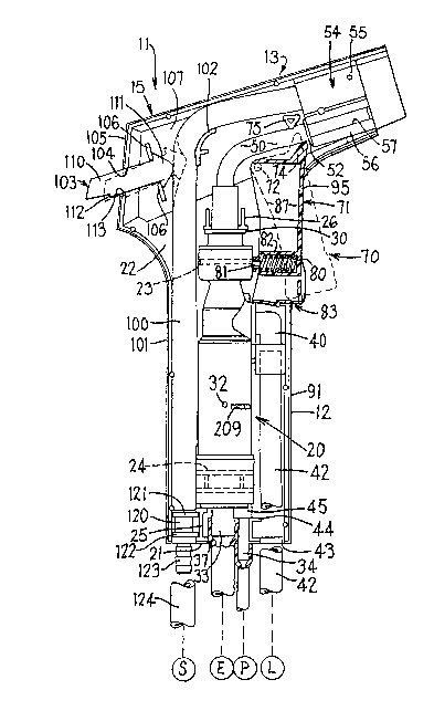
Turning to Figure 1, an irrigation handpiece 10 embody-
ing the invention includes a generally pistol-shaped
housing 11 including a butt, or handle, 12 engagable by the
hand of the user and a barrel 13 integrally fixed atop the
handle 12 and extending forward (rightward in Figure 1)
therefrom.
P~t~ 5
-- 6 --
In the embodiment shown, the housing 11 comprises
generally complimentary right and lefthand parts 14 and 15.
The housing preferably is of molded plastic material, for
example ABS. This facilitates not only formation of the
outer shape of the housing, but also formation on the
interial walls of the housing of a number of complexly
shaped stubs, hereafter specifically discussed (some mirror
imaged compliments and others not), usable to secure the
right and left housing parts in fixed registration with
each other and to locate the internal parts of the hand-
piece 10 in their working positions within the housing 11.
The right and left housing parts 14 and 15 are guided
together by pin-like stubs 16 (Figure 7) on the left
housing part 15 which are received in a conventional manner
in corresponding sockets (not shown) laterally opposed to
the pin-like stubs 16. For the most part, the pin-like
stubs 16 are disposed along the front, rear and top walls
of the leftward housing part 15.
Attention is directed to the contents of the housing
11.
A pressurized gas (preferably air) powered, pulsed
outlet, liquid pump 20 (Figures 2 and 7~ is located cen-
trally in the handle 12 and extends likewise substantially
from the bottom wall 21 of the handle upwardly therealong
into the barrel 13. The pump 20 is aligned substantially
parallel with the upstanding longitudinal axis of the
handle 12. The right and left parts 14 and 15 of the
housing 11 are concave and their opposed side walls 22
~Figures 2, 3 and 7) have similar, laterally cpposed,
concave, semi-circular upper and lower cradle stubs 23 and
24 (Figures 3 and 7), only those for the left housing part
15 being shown. The cradles 23 and 24 receive upper and
lower parts of the pump 20 and locate same fixedly against
lateral (right-left, and into-out of the page as seen in
. . :
2~ 7t~75
-- 7 --
Figure 2~ movement with respect to the housing 11 with the
right and left parts 14 and 15 assembled. The side walls
22 of the right and left housing parts 14 and 15 also
-Eixedly support opposed T cross-section stubs 25 extendiny
out from the bottom wall 21 of the housing, and a pair of
laterally opposed inverted T cross-section stubs 26 located
at the top of the handle 12. The stub 25 abuts the bottom
of the pump 20 and the stubs 26 abut the top of a flange 30
near the top of the pump to fixedly locate the pump verti-
cally therebetween. The pair of stubs 26 laterally ~right
to left in Figure ~.) locate an upper portion of the pump 20
snugly and fixedly therebetween to assist in lateral fixing
of the pump. Again, it will be understood that similar
stubs (not shown) on the right housing part 14 oppose the
stubs 25 and 26 shown in Figure 2 on the left housing part
15 for the same purpose. To further locate the pump
against the right-left movement in Figures 2, 3 and 7, a
cup-like stub 31, fixed on the inner face of the side wall
22 of the left part 15, receives a small lateral projection
32 (like that on the right side of the pump in Figures 2
and 7) on the left side of the pump 20 in a snug manner.
Extending downward from the bottom of the pump 20 are a
central tubular fitting 33 ~Figures 2 and 7) and an
eccentrically located, stepped, elongate tubular fitting 34
offset forwardly (rightwardly in Figure 2) of the fitting
33. Fittings 33 and 34 are male hose fittings which snugly
and slidably receive thereover the ùpper ends of respective
gas exhaust and pressure gas supply hoses 35 and 36. The
hoses 35 and 36 are conventional, clear, soft, resilient
plastic hoses. The exhaust hose fitting 33 is of substan-
tial larger diameter than the pressured gas hose fitting
34. The exhaust fitting 33 here terminates ~ust above the
bottom wall 21 of the housing while the reduced diameter
bottom end of the fitting 3A extends downwardly through the
~ 13~`9~ r t~
bottom wall 21. Opposed recesses 37 in the housing parts
14 and 15, namely at central portion of the bottom wall 21
forml in the assembled housing 11, an opening through the
bottom wall, through which the reduced diameter lower
extremity of the pressure gas fitting 34 snuyly extends,
and through which the gas exhaust hose 35 can upwardly
extend to sleeve over its fitting 33. The opposed recesses
thus form a very approximately keyhole shaped opening.
An inlet liquid fitting 40 (Figures 2 and 7), here in
the form of a 90 elbow, extends forwardly and downwardly
from the front face of the pump 20 at a point intermediate
the top and bottom ends thereof. The lower end of the
fitting 40 is belled at 41 to form a female Eitting end for
snugly receiving therein the upper end of an irrigant
liquid supply hose 42 (Figure 7). The irrigant liquid
supply hose ~2 extends downward from the belt mouth 41 of
the fittiny 40 through an opening in the bottom wall 2~ of
the housing formed by opposed semi-circular recesses 43 in
the right and left housing parts 14 and 15. Inverted L
cross-section stubs 44, fixedly laterally protruding from
the interior of the side walls 22 of the right and left
housing parts 14 and 15, oppose and extend toward each
other and are located laterally between the fitting 34 and
liquid inlet hose 42. The stubs 44 snugly abut the front
face of the fitting 34 and support the stepped fitting 34
at its downwardly facing step, i.e., support the enlarged
upper portion 45 of the pressure gas inlet fitting 34.
A pulsed irrigant liquid outlet tube 50 (Figures 2
and 7) extends upward from the top of the pump 20 into the
3~ barrel 13 and then angles forwardly along the barrel 13.
In one unit built according to the present invention, the
hose 50 was of a type provided with a flexible waterproof
core and braided fabric exterior for a lony working life
2~ i''J~t.
despite repeated pinchin~ of the tube to throttle the flow
from the pump 20.
A tubular front end fitting 51 (Figures 4 and 7) is
fixed to the front end of the hose 50 as seen in Figure 4.
The front end ittin~ 51 is rigid ancl has relatively small
radially outwardly extend.ing flanges 52 and 53 at the ends
thereof.
A two-cylinder over-under bracket 54 (Figures 3 and 7)
is aimed lengthwise of the barrel 13 and is fixed near the
front (rightward) end of the barrel. The bracket 5~ com-
prises an upper cylinder 55 to the underside of which is
fixed a parallel lower cylinder 6 which has a length
extending slot 57 to give it sufficient circumferential
resilient expandability to enable longitudinal insertion o~
the hose 50 and tubular front end fitting 51 rearwardly
therethrough prior to insertion of the lower end of the
hose 50 into the top end of the pump 20. In this way, the
front end of the liquid outlet hose 50 is rigidly fixed
with respect to the barrel 13. The upper and lower
cylinders 55 and 56 are fixed rigidly to each other by an
integral web 60 (Figure 3). Similar webs 61 and 62 fix the
top of upper cylinder 55 to the top wall 63 of the barrel
13 and fix the lower cylinder 56 to the bottom front wall
64 of the barrel 13, respectively. The webs 60-62 are here
in a common vertical plane substantially at the plane of
demarcation between the right and left housing parts 14 and
15, the webs 61 and 62 being on the left housing part as
seen in Figure 7.
A trigger unit 70 (Figures 2 and 7) comprises a hollow,
boxlike trigger 71 which is open on its rear edge adjacent
to the pump 20. Coaxial pivot pins 72 are fixed to and
extend toward the right and left housing parts 14 and 15
from fixed location on the upper rear corner of the trigger
71. The pivot pins 72 are pivotally received in laterally
3t~7~;7~;
-- 10 --
opposed bosses 73 fixed to the inner surfaces of the side
walls 22 of the right and left housing parts.
A spur 74 upstands from the upper right corner of the
trigger 71 and in the pulled-in position of the trigger 71
shown in Figures 2 and 3, the spur 74 lies close below the
hose 50 and behind the lower cylinder 56 so as not to
interfere with either one thereof. A triangular cross-
section anvil 75 projects rigidly from the interior face of
the side wall 22 of the left housing part 15 in contact
with the top of the hose 50. Both the spur 74 and anvil 75
are of rounded-point cross-section adjacent the hose 50, so
as to progressively compress the hose 50 therebetween as
the trigger 71 pivots forwardly from its solid line posi-
tion to its dotted line position shown in Figure 2. With
the trigyer in its full forward dotted line position of
Figure 2, liquid flow through the hose 50 is completely
shut off. The trigger 71 is located in a window 76
~Figure 3) in the upper front wall of the handle 12, the
window being sized to permit the trigger 71 to freely swing
between its rear and front positions shown in Figure 2.
A helical compression spring 80 ~Figure 2) continuously
resiliently urges the trigger 71 toward its forward dotted
line position of Figure 2. The spring 80 is of sufficient
strength to shut off liquid flow through the hose 50. On
the other hand, a human operator can easily o~ercome the
force of the spring 80 to pull the trigger 71 rearward and
hold it in any desired position between its dotted line and
solid line limiting positions in Figure 2. The spring 80
rests at its opposite ends on the front face of the upper
portion of the pump 20 and on the rear face of the front
wall of the trigger 71. The spring 80 is trapped by sn~gly
sleeving over a pin-like forward projection 81 on the front
face of the pump 20 and by being snugly but slidably
received in an axially elongate well 82 which projects
~'~.i~.7
rearward from the front wall of the trigger 71 substan-
tially to ~he rear edge of the trigger.
The trigger 71 can be locked in its rearward solid line
position Figure 2~ to permit ma~imum continuous irrigation
liquid flow through the hose 50, without need to manually
continuously pull the trigger 71 rearwardly, by a resilient
latch unit 83 shown in Figures 2, 2A, and 2B. More par-
ticularly, the mid and forward portions of the trigger
bottom wall 84 form a tongue 85 which is integrally and
resiliently hinged at 86 to the rear part of the bottom
wall 84 and extends forward therefrom. The side edges of
the tongue 85 are separated by fore-aft slots (Figure 2B)
from the side walls 87 of the trigger 71. The tongue 85
norm~lly barely clears the bottom edge 92 of the window
76 in the front wall 91 of the handle 12, in the manner
shown in solid line in Figure 2A. A forward facing, for-
wardly concave step 88 intermediate the front and rear ends
of the tongue 85 is located to trap therein the rear ed~e
of a small flange 90 projecting rearwardly from the front
wall 91, flush with the bottom window edge 92, when the
tongue 85 is manually bent downward at the resilient
integral hinge 86 to its lowered dotted line position 85'
of Figure 2A. In this lower position, the small forward
projecting lip 93, formed by the cavity of the fo~ward
facing step 88, becomes trapped beneath the flange 90, so
as to hold the tongue 85 latched in its downward dotted
line position 85' and accordingly to positively block the
trigger 71 from forward movement out of its rearward
limiting position shown in sol.id lines in Figures 2, 2A,
and 3, namely in a position where its sp~r 74 does not
interfere with flow through the hose 50.
The tongue 85 has integrally fixed to its front end an
upstanding front wall 94 which normally is substantially
flush with the front wall 95 of the trigger 71. A rearward
f~'7~
- 12 -
pull on the trigger 71, by reason oE user finger pressure
on the front wall 95 thereof, will move the rearward
located trigger 71 slightly further to the rear sufficient
to disengage the lip 93 from the flange 90 and let the
tongue 85 and front wall 94 thereon resiliently spring
upward from thair dotted line position to their solid line
position in Figure 2A, such that the trigger 71 is no
longer latched to the front wall 91 of the handle 12.
Thereafter, relaxing the rearward user finger force on the
trigger 71 will allow the trigger 71 to pivot forwardly
under the force of the spring 80 to progressively compress
the hose bet~een the spur 74 and an~il 75 and thus progres-
sively reduce, to zero, irrigant liquid flow through the
hose 50.
On the other hand, when it is desired to latch the
trigger 71 in its rearward, hose 50 open, position shown in
solid lines in Figures 2 and 3, the operator's fingers pull
the trigger 71 rearward to its rearward limit wherein the
lip 93 is above and slightly to the rear of the flange 90.
At that point, downward pressure of a finger of the user on
the forward bulge 96, near the bottom of the tongue front
wall 94, depresses the tongue 85 from its solid line posi-
tion to its dotted line position 85 wherein the lip 93 lies
below the flange 90. ~ slight relaxation of the rearward
force on the trigger allows the trigger to move forward
slightly, enough to trap the flange 90 within the forwardly
concave step 88 of the tongue 85, with the lip 93 remaining
trapped below the flange. In this way the trigger 71 is
restored to its latched position shown in Figures 2 and 3
(and in dotted line in Figure 2A), with the hose 50 open
Eor full flow.
In the embodiment shown, the handpiece 10 is adapted to
provide suction as well as pulsed irrigation at a surgical
site. Thus, a flexible suction hose 100 (Figures 2 and 7)
Z~;s~
- 13
extends from near the bottom wall ~1 of the handle upward
snugly between the pump 20 and rear wall 101 of the handle
and upward into the top portion of the barrel. The suction
hose 100 bends in a curved manner forward over a generally
"f" shaped anvil 102 and hence forward to seat within the
rear end portion of the upper cylinder 55 of the over~under
bracket 54.
A thumb button 103 (Figures 2 and 7) is yenerally
rectangular in configuration (and in the embodiment shown
open downwardly). The thumb button 103 is partially housed
in the rear end portion of the barrel 13. The rear end
portion of the thumb button 103 extends snuyly but slidably
through a rectangular window 104 in the rear wall 105 of
the barrel. The front portion of the thumb button 103 is
snugly slidably guided between a coplaner pair of plate
stubs 106 fixedly protrudiny from the inner face of the
side wall 107, in opposed coplaner pair of similar plate-
like stubs protruding from the opposed side wall of the
right housing part 14 toward the mentioned stubs 106 on the
left housing part 15. The thumb button 103 is thus guided
for movement by the window 104 and the stubs 106 for
sliding movement generally along the length direction of
the barrel 13. Opposed stubs 108 (Figure 7) are fixed to
and protrude toward each other from the barrel side walls
of the right and left housing parts 14 and 15. The stubs
108 slidably bear against the opposite sides 110 of the
thumb button 103 to prevent side to side pivoting oE the
thumb button. The front end of the thumb button 110 is
defined by a vertically enlarged, forward tapering head
111, which from the side looks much like an arrowhead with
a rounded point. The vertical enlargement of the head 111
prevents the thumb button from being pulled rearward beyond
its solid line position shown in Figure 2, by interferiny
with the front faces of the plate-like stubs 106.
J~J,~ 5
By pushing the thumb button 103 forward, by means of
the thumb of the user, the head 111 is pushed forward
toward the anvil 102 and thus progressively compresses the
suction hose 100 therebetween to progressively reduce
suction at the front end of the hose 100. With the thumb
button 103 in its forward-most position shown in dotted
line in Figure 2, the suction tube 100 is closed, between
the head 111 and anvil 102.
The rear bottom portion of the thumb button 103 is
relieved to form a rear facing step 112. By pushing the
thumb button forward and downward at its exposed rear end,
the bottom of the thumb button rides along the bottom edge
of the window 104 until the step 112 passes forward through
the window and drops down over the bottom edge of the
window 104 to its dotted line position in Figure 2. In
that position, the step interferes with the bottom edge 113
of the window 104 to latch the thumb button 103 in its
forward, dotted line, hose closed posit.ion to hold off
suction at the forward end of the hose 100 without need to
continue manual pressure on the thumb button 103. To
release the thumb button, the user merely lifts the exposed
rear end of the thumb button 103, for example by flicking
it upward with his thumb, whereupon the inherent resilience
- of the resilient suction hose 100 forces the thumb button
103 back to its retracted solid line rest position of
Figure 2, opening the suction hose to full flow.
In the embodiment shown, the bottom (Figures 2 and 7)
of the suction hose 100 has telescoped therein the upper
end of a conventional tube connector 120. The mid portion
of the tube connector 120 is spool-shaped, with upper and
lower flanges 121 and 122 which are gripped between the top
of the T-shaped stub 25 and bottom wall 21 of the handle 12
to fix the bottom of the suction hose 100 within the
housing 11. The ridged lower end 123 of the tube connector
- 15 -
120 is releasibly telescopingly received in the adjacent
end of a conventional external flexible suction tube 124.
The suction tube 124 leads to a suitable conventional
suctlon source S. Similarly, the external gas exhaust tube
35, pressure gas supply tube 36 and liquid supp:Ly tube 42
are connectable at their remote ends to a conventional
exhaust facility E, gas pressure (preferably air pressure)
source P, and irrigant liquid source L, as schematically
indicated in Figure 7. In the preferred embodiment shown,
the exhaust facility is not conventional but rather takes
the form of a special exhaust sound muffler hereafter
described.
A tip unit 125 (Figures 1 and 8-10) is releasably
mounted on the front of the barrel 13 and extends forward
therefrom. The tip unit 125 shown mechanically transforms
the means for providing suction and pulsed irrigant liquid,
from the parallel resilient hoses 50 and 100 within the
barrel 13, to form a single ridge of clear plastic barrel
extension 126 (Figure 9) which can be inserted into the
area of a wound during surgery for providing suction and/or
pulsed irrigant liquid flow.
Interposed between the barrel extension 126 and the
barrel 13 the tip unit 125 includes rearward facing insert
127 telescoped partly in a body 128 (Figures 8 and 9).
The insert 127 has a forward facing recess 130 defined
by a rear wall 131 from which extends forwardly a perimeter
flange 132. The body 128 has a rearwardly facing recess
133 defined by a front wall 134, rearwardly from which
extends a perimeter flange 135. In the embodiment shown,
the front wall 134 extends radially beyond the perimeter
flange 135 both sidewardly and upwardly. The body
perimeter wall 135 has a rearward facing internal step 138
(Figure 8). The perimeter flange 132 of the insert 127 is
inserted forwardly into the recess 133 in the body 128
2~3~`~t7t;~ S
- 16 -
until it comes to rest against the step 138, in which the
position it is fixed, by any convenient means such as
adhesive bonding. The result is that the communicating
recesses 130 and 133 form an approximately rectangular
suction chamber 137 (Fiyures 9 and 10).
A hollow suction boss 140 extends integrally rearwardly
from the rear wall 131 of the insert 127. The boss 140 has
an external annular rib 141 and small bumps 142 by which it
is guided into snug, substantially sealed relation in the
upper cylinder 55 of the over-under bracket 54 adjacent
front end of the barrel 13 (Figure 9). When thus
releasably inserted, the rear face of the front wall 134 of
the body 128 abuts the front end of right houslng part 14
and left housing part 15 and the rear end of the suction
boss 140 lies adjacent the front end of the suction hose
100 .
A hollow suction boss 143 extends fixedly forward from
the front wall 134 of the body 1~. Stepped within the
boss 143 is an elongate, forward extending, large bore tube
144, here equipped with a forwardly opening, U-shaped
diametral slot 145 at the front end thereof. The large
tube 144 defines the external part of the barrel extension
126. In this way, the suction path extends forward from
the hose 100 through the boss 140, suction chamber 137,
boss 143 and large tube 144 to conveniently bring suction
to any desired position of the surgical site.
As seen in Figure 9, the suction boss 140 is offset
vertically above the suction boss 143 so that the suction
chamber 137 provides a vertical transition in flow.
A hollow irrigant liquid boss 146 (Figures 8 and 9)
fixedly extends rearwardly from the rear wall 131 of the
insert 127 in spaced relation below the suction boss 140.
The liquid boss 146 is annularly grooved at 147 to receive
an 0 riny 148. The liquid boss 146 with its 0 ring 148 is
~q~ 75
- ~7 -
snugly and sealingly received in the free end of the
fitting 51 on tha front end of the pulsed irrigant liquid
hose 50 ~Fi~ures 4 and 7), which in turn is clamped in the
generally C-shaped cross-section lower cylinder 56 of the
over-under bracket 54 at the forward end of the housing
barrel 13. The radial web 150 within and intermediate the
ends of the fittin~ 51 supports a rearward extending nipple
151 (Figure 4) over which the front end of th~ hose 50 is
snugly and sealingly seated. The liquid boss 146 extends
substantially to the web 150. A further liquid boss 152
extends fixedly forward from the rear housing wall of the
insert 127, in coaxial communication with the liquid boss
146. A small diameter irrigation tube 153 of rigid, prefe-
rably clear, plastic material is seated in its rear end
sealingly in the boss 152 and extends forward therefrom
alon~ the bottom portion of the large tube 144. The ir-
rigation tube 153 is substant.ially smaller in diameter than
the large tube 144 and is located eccentrically therein,
namely below the central axis thereof. The front end of
the irrigation tube 153 is snugly received in and sealed
with respect to a restrictive nozæle 154 located just
inboard of the forward end of the large tube 144 and aimed
forwardly through the open front end of the large tube 144.
The nozzle 154 is of resiliently flexible plastic material
and includes sidewardly extending resiliently bendable
wings 155 resting within the suction tube 144 to help
stabilize the forward end of the irrigation tube 153.
The tubes 153 and 144 together form the barrel exten-
sion 126.
The tip unit 125, comprised of the insert 127 fixedly
telescoped in the body 128 and the barrel extensioll 126
extending forwardly therefrom are releasably inserted in
the front end of the barrel 13 as follows. The bosses 140
and 146 are telescopingly received, as above discussed, in
-- 18 --
the upper barrel 55 and fitting 51 (in turn received in the
lower barrel 56 of the housing 11). In addition, the top
and sides of the perimeter flange 135 of the body 128 are
snugly but slidably received in the front end of the barrel
13, and the rear face of the front wall 134 of the body 128
abuts the front face of the right housing 14 and left
housing 15. In this way, the barrel extension 126 is
located rigidly with respect to the barrel 13 and projects
forwardly therefrom. To prevent the tip unit 125 from
inadvertently escaping forwardly from the front end of the
barrel 13, the two are connected by a latch unit 160
(Figure 10). A tongue 161 (Figure 8) extends rearwardly
from the right side of the perimeter flange 135 of the body
128. The tongue is
resiliently bendable toward the vertical central plane of
the tip unit 125 (toward the point of the axis of the
bosses 140 and 146~. The rear end of the tongue 161 has a
laterally outboard flange 162 defining a forward facing
latch step 163. Rearwardly and outwardly Eacing ramp
fingers 164 extend rearward from the outboard face of the
flange 162. The right side of the barrel 13 has a latch
opening 166 (Figure 10) therethrough which defines a rear
facing latch step 167 in part defined by a forwardly and
laterally inwardly facing ramp 170. Upon insertion rear-
wardly of the tip unit 125 into the front end of the barrel
13, the ramp fingers 164 enter a forwardly extending and
laterally inwardly facing longitudinal groove 171 in the
inner surface of the right half of the barrel 13. Con-
tinued rearward insertion of the tip unit 125 into the
front end of the barrel 13 causes the ramp fingers 164 to
slide to the rear end of the groove 171, and climb
laterally inward along the ramp 170, thereby bending the
tongue 161 laterally inward. Eventually, as the tip un,it
125 reaches its fully inserted position within the barrel
~ . i 7 ~ 75i
-- 19 --
13, the flange 162 slides over the rearward tip of the ramp
170 and resiliently latches over the step 167 to achieve
the latched position shown in Figure 10. Interference
between the flange 162 and step 167 positively precludes
the tip unit 125 from being withdrawn forwardly from the
front end of the barrel 13.
When it is desired to withdraw the tip unit 125 from
the front end of the barrel 13, the operator simply presses
laterally inward a release lever 173 accessible on the
right side of the barrel 13. The release lever 173 is
integrally hinge~ ~bendably connected) at its rearward end
to the right side wall of the barrel 13. The front end of
release lever 173 is provided with a laterally inward
protrusion 174 laterally facing the flange 162 on the
tongue 161. Thus, to release the tip 125 fro~ the barrel
13, the operator simply presses laterally inward the
release le~er 173 to pivot the protrusion 174 inward su~fi-
cient to displace the flange 162 laterally inward of the
step 167. The tongue 1~1 thus being freed from the step
167, the tip unit 125 is free to be pulled forwardly out of
the front end of the barrel 13.
Turning now to a preferred embodiment of the pump 20,
attention is directed to Figures 4 and 5. The pump 20
comprises an elongate hollow pump casing 190 comprising an
open ended cylindrical body 191 and top and bottom end caps
192 and 193. The casing 190 contains an elongate
cylindrical circular cross-section main bore 194. The
downward ~rightward in Figure 4) facing step 195 separates
the main bore 194 from a short, upper, circular cross-
section, cylindrical bore 196. The bore 196 is continued
upward (Figure 4) by a frustoconical portion 197. The
upper end of the frustoconical portion 197 communicates
with a recess 200 in the upwardly opening, cup-shaped upper
end 201 of the casing 190.
~5l?7 ~ ~S
- 20 -
A piston 202 is axially slidable in the main bore ~94.
The piston 202 is a one-piece generally spool-like member
comprising an upper pumping head 203 and a lower pressure
gas motor head 204 of the same diameter. The heads 203 and
20~ are axially spaced by an integral, reduced square cross
sectional portion 205. Each of the piston heads 203 and
204 has an annular groove 206. An annular slipper seal 207
is seated in the groove 206 in each head. In the embodi-
ment shown, the slipper seals 207 are of U-shaped cross-
section opening concavely radially inward, with an 0 ring
208 sandwiched radially between the slipper seal and the
bottom of the corresponding piston groove 206, the o ring
208 being received in the radially inwardly opening concave
face of the slipper seal 207. The slipper seals 207 permit
up and down sliding motion of the piston 202 while
preventing fluid leakage axially past each piston head 203
and 204. The piston heads 203 and 20~ divide the bore 19~
into three axially spaced chambers, namely an upper liquid
chamber 210 which extends into the bore 196 and frusto-
conical portion 197, a middle leakage gas escape chamber
211 and a lower pressure gas chamber 212.
The middle chamber 211 opens through a vent 209 (Figure
4) in the side of the casing body 191. Thus, the middle
chamber 211 is continuously vented to the interior of the
handpiece housing 11 and thereby, through the several
openings in such housing, to the exterior. The vent 209 is
positioned vertically to continuously communicate with the
space between the piston heads 203 and 20~ throughout the
permitted vertical travel of the piston. Thus, should any
leakage of pressurized gas unexpectedly occur upward past
the seal 207 on the pressure gas motor head 20~, such
pressure ga~ will be vented at 209. This positively
precludes a buildup of gas pressure in the middle chamber
211 between the piston heads 203 and 20~ and thereby posi-
2~ 7~t7
tively precludes any possible leakage of pressurized gas
upward past the seal on the pumping head 203 and into the
irrigant liquid in the upper chamber 210 extending verti-
cally above the pump.ing head 203 through the bore 196 and
frustoconical portion 197.
The piston 202 has a coaxial, reduced diameter,
cylindrical tail extending below the pressure gas motor
head 204 into the pressure gas chamber 212. An axially
elongate, cylindrical, generally cup-shaped poppit 214 is
axially slidably sleeved snugly over the tail 213 in the
pressure gas chamber 212. The internal depth of the poppit
214 is substantially equal to the axial length of the tail
213.
The poppit 214 has a radially extending flange 220 near
its upper end which extends close to but clears the inner
wall of the bore 194. Axial passages 221 in the flange 220
permit free gas flow axially past the flange 220. The
poppit has a closed bottom wall 222.
A transverse pin 215 is fixed in and extends radially
beyond a transverse hole 216 diametrically located in the
tail 213 near its bottom end. The protruding ends of the
pin 215 extend through and radially beyond diametrically
opposed, axially extended slots 217 (Figures 4 and 5) in
the lower cup 218 of the poppit 214. The slots 217 permit
free upward displacement of the piston 202 with respect to
the poppit 214. A lower helical compression spring 226
snugly but slidably surrounds the cup 218 of the poppit
214. The spring 226 is axially trapped between the flange
220 and a washer 228 which axially slideably surrounds the
cup 218 and is trapped between the spring 226 and the outer
ends of the pin 215. The spring 226 axially urges the
poppit against the motor head 204.
A further helical compression spring 227 is axially
trapped between the step 195 and upper, pumping head 203 so
~ 3fl~ 6 7 S
- 22 -
as to continuously resiliently urge the piston 202 and
poppit 214 downward against the bottom end cap 193. The
upper spring 227 is snugly but slidably received within the
main bore 194.
The bottom end cap 193 is fixed to the bottom of the
body 191 in sealed relation, here by snap fit telescoping
over the bottom portion of the body 191 with an O ring seal
230 ~Figure 4) sandw.iched between the bottom of the body
191 and upward facing step 231 on the bottom end cap. The
bottom end cap 193 has a central upstanding boss defining
an upward facing horizontal exhaust gas valve seat 232.
The upper spring 227 normally presses the poppit bottom 222
downwardly against the seat 232 to close an exhaust port
233 extending coaxially downward therethrough and in free
communication with the exhaust fitting 33, which opens
thereto and extends downward from the bottom end cap 193.
An upward opening annular recess 234 is formed in the
top of the bottom end cap 193 and loosely surrounds the
exhaust gas valve seat 232. The pressure yas fitting 34,
which depends downward from the bottom end cap 193 and is
located eccentrically thereof, communicates at its upper
end through a restrictive orifice 235 with the annular
groove 234 and thus with the lower pressure gas chamber 212
surrounding the poppit 214.
Liquid inlet and outlet check valves 240 and 241 permit
liquid flow fr3m the inlet liquid fitting 40, through the
bore 196 and frustoconical portion 197 and into the top end
cap 192 but prevent opposite flow. The check valves 240
and 241 cooperate with the pumping head 203 to form a
pulsing liquid pump. The check valves 240 and 241 are, for
example, conveniently provided as flap valves in the manner
shown in Figure 4. Flap valves conveniently occupy very
little space and can be made and housed inexpensively.
Conventional flap valves comprise a disk of moderately
76 ~ i~
- 23 -
flexible material, as illustrated for example with respect
to the flap valve 240 of Figures 4 and 4A, having a
flexible, centrally located tongue 242 formed by a
generally C-shaped slit 243 through the thickness of the
material of the flap valve.
A stepped recess 244 in the front side of the pump
casing 190 opens into the bore 196 and snugly receives the
flanged outlet end 245 of the liquid inlet elbow 40. The
outflow end 245 of the elbow 40 is fixed within the recess
244 by in the convenient means, for example th~ conven-
tional adhesive bonding. To help fix the elbow 40 reliably
in the recess 244 ~Figure 4), a stub 247 fixed on the
belled lower end 41 of the elbow 40 is snugly received in a
blind hole 248 in the opposed front side of the pump body
191 and may be secured therein by any convenient means such
as adhesive bonding. The perimeter of the flap valve 240
is fixedly trapped between the elbow end 245 and the step
246 of the recess 244. The perimeter of the corresponding
flap 242 is backed on its exterior face by a portion of the
flanged end 245 of the elbow 40 to prevent the flap 242
from bending rightwardly loutwardly) past its flat solid
line position of Figure 4, in which position the flap valve
240 is closed. Qn the other hand, the diameter of the step
246 is sufficient to free the flap 242 to resiliently bend
inward as indicated in broken lines in Figure 4, in
response to pressure in the elbow 40 exceeding the vacuum
in the bore 196 and frustoconical portion 197, to open the
valve 240 and admit liquid from the elbow 40 into the bore
~96.
In the embodiment shown, the outlet check valve 241 is
constructed and mounted similarly to the above described
inlet check valve 240, but of course is arranged for per-
mitting outflow upwardly out of the liquid chamber 196,
197. In the embodiment shown, the depending skirt 250 of
~Z~3(~6'~
- 24 -
the top end cap 1~2 is snap fitted down into the recess 200
at the upper end of the casing 190 to clamp the perimeter
of the outlet ~lap valve 241 downward against the annular
bottom 251 of the recess 200. The bottom 251 extends
radially inward sufficient to support the perimeter portion
of the corresponding flap 242 so that it cannot bend down-
ward beyond its solid line position shown in Figure ~. The
internal diameter of the skirt 250 is large enough to clear
the flap 242 and permit it to bend up~ardly, as indicated
in broken line in Figure ~. Accordingly, the outlet check
valve 241 permits the flow of liquid in only one direction
therethrough, namely upward (with the flap bent upward as
shown in broken line 242 in Figure 4).
The upper end of the top end cap 192 receives the
corresponding end of the hose 50 in an annular recess,
snugly and sealingly telescoped over an upstanding nipple
252 defining the central portion of such annular recess and
communicating with the top end of the interior space 253 of
the top end cap 192.
In addition to the pin-like stubs 16 above-described,
an additional pin-like stub 260, protruding laterally
inward from the over-under bracket 54, may cooperate with a
suitable socket not shown in the rightward part 14 of the
housing to further lock the housing parts in registry
together. If desired, other ones of the above-described
stubs may be utilized for this same purpose of assisting
registration of the two housing parts, for example anvils
75 and 102 may cooperate with complimentary parts (not
shown) laterally opposing the same and ~ixed on the inner-
face of the rightward housing part 14. Using the various
stubs 16, 260, etc., the two housing parts, with the
remainder of the apparatus properly located therein, can be
permanentl~ bonded together. Pin-like stub 261 (Figure 7)
is a stop post to prevent the tip release button 173 from
7$
- 25 -
bending inwardly so far as to break off at the hinge, when
handpiece is assembled.
The apparatus above-described is preferably constructed
of surgical grade materials. For example, the housing 11,
trigyer 71, pump parts 190, 192, 193, and 202, the fitting
51, .he connector 120, the thumb button 103, the insert 127
and the body 128 may be molded of surgical grade ABS. The
poppit may be of a suitable plastic material, for example a
material sold under the trademark Santoprene. The elbow 40
may be, for example of high impact polystyrene. Metal
elements are preferably of stainless steel. Flexible
tubing is preferably of soft PVC or latex. The tubes 144
and 153 of the barrel extension 126 are preferably of
butyrate or rigid PVC.
In the preferred embodiment shown, the exhaust line 35
terminates in a muffler 270 (Figure 11) intended to muffle
the sound of exhaust air. The muffler is locatable dis
tance (for example six feet) from the surgical site, by use
of a suitably elongate exhaust hose 35. The muffler 270 in
the preferred embodiment shown comprises a flexible, elon~
gate, circular cross-section accordion sleeve 271 of
suitable resilient plastic material, corrugated over the
major central length thereof and cylindrical at the ends
thereof for telescoped reception therein of inlet and
outlet end caps 272 and 273.
The inlet end cap 272 has central coaxial inner and
outer nipples 274 and 275, the exhaust hose 35 being snuyly
sleeved over the exterior nipple 274. The internal annular
flange 276 snugly and fixedly receives thereover the
adjacent end of the sleeve 271.
The outlet end cap 273 is generally cup-shaped, having
an annular side wall 280 over which is snugly and fixedly
sleeved the remaining end of the sleeve 271. A recessed
radial end wall 281 closes the axial inner end of the cup-
7 ~
- 26
shaped outlet end cap 273. Circumferentially distributed
axial spacers 282, hare three in number, extend from the
end wall 281 axially into the interior of the sleeve 271.
A loose mass 283 of randomly distributed fiber, -for example
synthetic fiber such as Dacron (TM), partially fills the
sleeve 271. Passages 285 pierce the end wall 281 and side
wall 280 of outlet end cap 271.
Exhaust gas flows from the tube 35 into the corrugated
accordion shell 271, diffuses through the mass of fibrous
material 283 and exits through the passages 285 in the
dished central recess 284 of the outlet end cap 273. The
pressure gas escapes from the pump portion of the motor
intermittently, i.e., in a pulsed fashion. The wave fronts
of the pulses are substantially reduced in amplitude and
sharpness by the damping provided by the fibrous mass 283
and also by the axial expandability of the corrugated,
accordion-like shell 271 (particularly note the typical
solid line retracted position 273 and expanded position
273' o~ the outlet end cap, corresponding to the contracted
and axially expanded conditions of the accordion-like shell
271). The result is a relatively smooth, quiet exhaust
flow out of the recess 284 of the outlet end cap 273 as
compared to a relatively noisy pulsed air outflow which
would exit from the exhaust tube 35 if the muffler 270 were
not present.
OPERATION
The operation of the apparatus will be apparent from
the foregoing description. However, aspects of the opera-
tion are summarized below for convenient reference.
~he pump 20 (Figure 4) is readily assembled by axially
inserting the piston 202, poppit 214, and associated
springs 226 and 227 upward into the bottom of the body 191
and adding the lower end cap 193. The check valves 240 and
241 are installed and held in place by installation of the
Zi~>~67~3
- 27 -
overlying elbow 40 and overlying top end cap 19~ respec-
tively. Thereafter the adjacent ends of the hoses 35, 36,
42 and 50 are slid into place as shown in Figure 4. Adding
the fitting 51 to the free end of the hose 50 completes
assembly of the Figure 4 pump.
Thereafter, the assembled pump 20, together with the
suction hose 100, fitting 120, trigger unit 70 and thumb
button 103 are installed in the left housing part 15 in the
manner shown in Figure 2 and above discussed. This
includes insertion of the forward end of the suction hose
100 and fitting 51 into the over-under bracket 54 as above
discussed with respect Figures 2 and 9.
The right housing part 14 can then be placed in
registry on the left housing part 15 and its contents are
held in place thereon by mechanical snaps fit with the
possible aid of adhesive bonding.
With the tip unit 125 assembled in the manner above
discussed with respect to Figures 8-10, the tip unit 125
can be releasably .installed in the front end of the barrel
13 and held latched therein hy means of the latch unit 160.
Attention is directed to the operation of the pump 20
(F~gures 4, 6A and 6B). Figure 4 indicates the normal rest
condition of the pump. Gas under pressure (preferably
filtered air) continuously feeds from the hose 36 through
the restrictive orifice 235 into the pressure gas chamber
212. The restrictive orifice 235 limits the amount of air
that can feed from the hose 36 into the pressure gas
chamber 212 in the hereinafter described last portion of
the operational cycle illustrated in Figure 6B, namely with
the poppit 214 shifted up off its seat 232. On the other
handl the orifice 235 i5 of sufficient size to admit here
to the pressure gas chamber 212 fast enough to cycle the
reciprocation of the piston at the desired rate. In one
example, the restrictive orifice had a diameter of .040.
7~
- 28
Pressurized air entering the pressure gas chamber 212
raises the upward pressure on the motor head 204 and gradu-
ally raises the piston 202 against the force of the upper
spring 227. If the upper (liquid) chamber lg6, ~97 is
filled with liquid, as it would be during ongoing operation
of the pump, then the rising pumping head 203 will push
li~uid against the valve flap 242 of check valve 241 and
opsn same to deliver liquid throuyh the top end cap 192,
hose 50, fitting 51, to and through the Figure 9 tip unit
125 to squirt forwardly from the nozzle 154. At the same
time when the piston 202 moves upward the other valve flap
242 of the check valve 240 closes against a portion of wall
245 of elbow 40 so as to prevent liquid from exiting
through elbow 40.
Continued rising of the piston 202 continues this
action and eventually the piston reaches its Figure 6A
position with the motor head 204 spaced well above the
poppit 214 and the piston mounted pin 215 near but out of
contact with the upper end of the slots 217 in the opposed
sides of the poppit cup 218. In this position the pressure
in the pressure gas chamber 212 is virtually at its maximum
and the upper spring 227 is nearly fully compressed. The
liquid pumping chamber 196, 197 is substantially at minimum
volume such that more liquid has been continuously driven
therefrom out the nozzle 154 (Figure 9) as the piston 202
advanced upward from its Figure 4 to its Figure 6A posi-
tion. In addition, during that upward rise of the piston,
the lower spring 226 has become further compressed due to
the rise of the pin 215 along the slots 217 in the poppit
214.
Note that the middle chamber 211, defined between the
piston heads 203 and 204 still is vented through the vent
209 despite the upward rise of the piston 202, such that if
air should unexpectedly and accidentally leak upward past
7~7~j;
the piston motor head 204, such air would be vented through
the vent 209 before it could build up in pressure to any
level sufficient to leak upward past the pump head 203 and
into the liquid chamber 196, 197. Thus, there is no pos-
sibility of pressurized air emerging from the nozzle 154
(Figure 9) in the barrel extension 12 6 .
The piston 202, having risen to the Figure 6A position,
has now nearly brought the poppit 214 to a condition of
instability. The poppit 214 in ~igure 6A is still resting
upon and closing the exhaust gas valve seat 232 and is held
down upon such seat 232 by the pressure of air in the
pressure gas chamber 212, which pressure is applied through
the slots 217 to atop the closed bottom wall 222 of the
poppit 214 and also through axial passages 221 to atop
flange 220 of poppit 214. The clownward gas pressure on the
poppit bottom wall 22z and top flange 220 has firmly held
down tlle poppit 214 to close the exhaust valve seat 232
during the rise of the piston from its Figure 4 starting
position to its Figure 6A position. However, in the Figure
6A position the lifting force of the increasingly com-
pressed spring 226 has risen almost to the level required
to overcome the downward force on the poppit due to air
pressure atop the poppit bottom wall 222 and top flange
220. The poppit is thus closely approaching vertical
instability.
In the sliyht additional rise of the piston 202 from
its Figure 6A to its Figure 6B position, the additional
minor compression of the spring 226 causes the upward
spring force on the poppit 214 to exceed the downward force
of gas pressure holding the bottom 222 of the poppit closed
downward on the exhaust seat 232. As a result, the spring
226 lifts the poppit 214 slightly off the valve seat 232.
Therefore, pressurized air in the pressure gas chamber 212
starts to leak out through the exhaust port 232. Gas
- 30 -
pressure within the chamber 212 thus drops rapidly. The
downward gas force on the poppit and the upward gas force
on the piston head 204 thus diminishes rapidly. The spring
226 thus rapidly lifts the poppit 214 up from its Figure 6B
position and the spring 227 forces the piston 202 downward
and the two abut at an intermediate position of the dis-
tance shown in Figure 6B between the piston head 204 and
the top of the poppit 214. In other words the poppit 21.4,
as soon as it reaches instability, virtually instantan-
eously "pops" open. Thus gas pressure in the chamber 212
very rapidly drops to atmospheric pressure by exhausting
air out the open port 233. As air pressure rapidly drops
in the chamber 212 the down force of the compressed upper
spring 227, pushing down on the piston, quickly more and
more exceeds the up force on the piston due to air pressure
in the chamber 212, with the result that the piston 202 is
accelerated downward by the vertically expanding spring
227. This downward acceleration of the piston 202 by the
spring 227 even more rapidly drives the remaining excess
gas from the chamber 212 through the open exhaust port 233.
The downwardly accelerating piston 202, by reason of its
lower ~motor) head 204 bearing on the top of the poppit
214, returns the poppit downwardly as well. The piston 202
and poppit 214 thus move downwardly toward their Figure 4
starting position.
During the time when the exhaust port 233 is open, air
from the compressed air source can still enter the chamber
212 from the fitting 34. However, the rate of flow of
pressure air into the chamber 2~2 is limited by the
restrictive orifice 235. Therefore, the loss of air from
the compressed air fitting 34 out the open exhaust port 233
is minimized and does not represent a significant energy
loss. The downward stroke of the piston 202 and poppit 214
ends when the poppit reaches and closes the exhaust port
2lI~7~i lr'5
233, i.e.l when the piston and poppit have returned fullyto their Figure 4 starting position.
The foregoing describes one cycle of operation of the
pump 20. It will be understood that the pump continues to
cycle in the above manner while adequate air under pressure
is supplied at the fitting 34 and liquid is free to flow
out the nozzle 154 (Figure 9).
As the piston 202 moves downward, the pressure in the
chamber 196, 197 is correspondingly reduced, which pulls
closed the outlet check valve 241 and pulls open the inlet
check valve 240 to admit further irrigant liquid to the
liquid chamber 196, 197 above the pumping head 203 of the
piston 202. The check valvas 240 and 241 continuously
cycle with the rise and fall of the piston to pass a series
of liquid pulses out the nozzle 154 (Figure 9).
In starting operation of the pump 20 initially, with
the liquid tube 42 connected to a liquid source but without
it having liquid drawn into the elbow 40, continued
operation of the pump (reciprocating of the piston 202 and
cycling of the valves 240 and 241) will pump air from the
elbow 40, dropping the pressure in the elbow 40 to tend to
draw liquid thereinto. It has been found that the pump
will self prime from a source several feet below it in this
manner.
In one apparatus constructed according to the inven- -
tion, an air pressure source of 80 to 125 PSI was employed.
With about 125 PSI air applied to the tube 36 at its inlet
end (not shown), and with the trigger 71 fully pulled to
fully open the liquid output tube 50, a maximum flow rate
of 900 to 1000 ml. per minute of liquid, the latter cor-
responding to about 1000 pulses per minute of irrigant
liquid, was achieved. Flow rate and pulses per minute are
both reduced when the tube 50 is only partially opened (the
trigger is only partially pulled), or the air pressure in
2~ ,;P7,5
line 36 is reduced. Flow rate and pulse rate are reduced
to about half the above described rate (to about 500 ml.
per minute and 500 pulses per minute), when the air pres-
sure applied to the remote end of the tube 36 is about 80
PSI, in the example above discussed.
Thus, gradual pulling of the trigger gradually
increases both the irrigant liquid flow rate and pulse
rate.
With the handpiece lO connected to suction source S,
exhaust means E, pressure air source P, and irrigant liquid
source L, the trigger 71 will normally be in its dotted
line "off" position to close the irrigant liquid hose 50.
The thumb button 103 will normally be in its solid line
"on" position. The surgeon can insert the forward end of
the barrel extension 126 (Figure 9~ into proximity with a
surgical site and can apply pulsed irrigation liquid and/or
apply suction to draw away the debris, as desired.
Progressively pulling in the trigger 71 toward its
solid line position in Figure 2 progressively unclamps the
pulsed irrigation hose 50 to provide the desired frequency
and volume of pulsed irrigant flow through the nozzle 154
(Figure 9) toward the surgical site. The trigger 71 can
be, if desired, locked in its solid line, fully open posi-
tion of Figure 2, in the manner above discussed.
The suction button 103 can be pushed in and down to
lock and block suction oEf, as discussed above. Lifting
the rear end of the thumb button 103 unlocks it and the
user can reduce thumb pressure on the thumb button 103 to
allow it to progress rearwardly toward its solid line
Figure 2 position. This gradually unblocks the suction
hose 100 and provides progressively stronger suction at the
front end of the large tube 144 of Figure 9 to remove
debris from the surgical site.
Zi3~
- 33 -
After completion of the surgical procedure on the
patient, the handpiece 10 (if desired along with its
associated hoses 124, 35, 36 and 42) is intended to be
discard d, so as to minimize the possibility of contamina-
tion of a later patient.
Although a particular preferred embodiment of the
invention has been disclosed in detail for illustrative
purposes, it will be recognized that variations or modifi-
cations of the disclosed apparatus, including the re-
arrangement of parts, lie within the scope of the present
invention~