Note : Les descriptions sont présentées dans la langue officielle dans laquelle elles ont été soumises.
37~
COMPOSITE AND SELF-LUBRICATING BUSHING AND METHOD FOR MAKING SAME
BACKGRO~ND OF TnE INVENTION .
.... : ,
The present invention relates to bushings and, more
particularly, to a composite and self-lubricating bushing for use
in die sets, presses and other heavy duty machinery. The
invention also relates to a method for the manufacture of a
cylindrical bearing surface finding advantageous use in such a
bushing.
It is well known in the tool and die industry that long-
lasting, precision bushings are an important component in the
design of commercially acceptable die sets. Because these
bushings are often subjected to high press velocities and
substantial side thrust forces, it is necessary that they be
formed from a monolithic block and that they be carefully
constructed to exacting specifications. Two types of plain guide
bushings are well known to the art and normally available from
most die set manufacturers, namely hardened steel bushings and
plated bushings in which a thin layer of bronze is plated in the
bore of a steel bushing. In either case, the bushing is closely
, fitted to a hardened and ground guide post with a diametral
clearance ranging from about 0.0003 to 0.0008 inches. Blanking
and piercing dies must be closely fitted to avoid shearing the
cutting edges, while forming dies will- work well with larger
clearances.
~ardened steel bushings are widely used at present and, when
properly lubricated and maintained in alignment, will provide
- 2 -
2~C~7~l 33
excellent service and wear life at moderate press speeds. For
applications with higher speeds or higher ~ide loads, bronze
placed bushings are preferred because they reduce chances of
galling or siezing. These bronze plated bushings must also be
lubricated regularly to avoid failure.
Some prior art dies, where greater pin and bushing clearance
can be tolerated, may be fitted with solid bronze bushings
inserted into the steel or iron body of the die. These bushings
are more tolerant of dirt or fine metal particles which find
their way into the space between the guide post and bushing and
become embedded in the bronze. A plated bushing would have too
thin a layer of bronze to accept anything but the finest of
foreign particles and the hardened steel bushing would be even
less tolerant. The disadvantages of solid bronze are lower
mechanical strength and a coefficient of expansion significantly
greater than that of steel. Thus, as the bushing heats in
service it tends to close in on the guide post adding to the
heating problem. Sufficient clearance and lubrication must be
provided to avoid this problem.
I~ is well known to provide all of these prior art bushings
with means for lubrication, such as a lubricating fitting so that
~grease or other lubricants may be periodically introduced to the
internal bearing surface. However, under high velocity and
extreme load conditions such lubricants are quickly dissipated;
and if the tool operator is not diligent in the proper and
periodic application of lubricant, it is possible that a bushing
'
2(~
may sieze despite all of the foregoing design precautions. Thus,
a need exists in the industry for a quality bushing for use in
die sets and in other high load applications which is capable of
self-lubrication for extended periods of service.
One of the important properties of bronze as a bearing
material is its ability to conduct heat away from the bearing
surface. For example, coefficients of heat transmission for
bronze are about five times greater than steel. Therefore, a
need exists for a bushing having a lining of bronze thick enough
to conduct heat away but not so thick as to cause sùbstantial
reduction of the clearance between guide post and bushing.
Another well known bearing material is a porous sintered
; bronze which has the advantage of holding a lubricant in as much
as 25% of its volume. However, all known prior art applications
~15 oÇ such a sintered bronze have involved bearings fabricated from
sheet stock. When formed into a bearing, the body of such
bearings includes a separation line typically formed when the
sheet stock is rolled into a cylindrical configuration. ~hus,
; the resulting bushing is not a monolithic structure.
Accor~ingly, these bearings are used only in commercial
applications under conditions of moderate loads. They are not
u,sed as guiding elements in die sets primarily because of
inferior strength and load carrying ability.
:-r - . . . ~ , :
. .. . .
~ Z~)7~33
, .
SUM~ARY OF T~E INVENTION
The present invention is therefore directed to a novel
composite bushing which employs a monolithic steel body and a
compacted and sintered porous bearing layer which is formed on an
internally machined cylindrical surface of the steel body.
The present invention is also directed to a novel and
uniquely constructed bushing which overcomes the disadvantages
associated with the prior art by incorporating 1nto the bushing
itself a means for lubricating the bushing's internal bearing
surface over extended periods of service. Thus, the bushing of
the present invention comprises a cylindrical body including an
internal cylindrical bearing surface, a cavity or reservoir for
storing a liquid or semi-liquid lubricant, at least one
passageway extending between the cavity and the bearing surface
to permit the flow of lubricant from the cavity to the bearing
surface, and finally a cover or casing which is mounted to and
over the bushing body to enclose the cavity.
In accordance wi.th.a preferred embodiment of the invention
the bushing also includes one or more recesses extending along
the internal bearing surface and in communication with the
~assageway from the lubricant reservoir~ This recess facilitates
distribution of the lubricant on the internal bearing surface.
In addition, the bushing body may also include an externally
accessible filling port which communicates with the lubricant
reservoir within the bushing body. Finally, the self-lubricating
2(~17615~
~ " ,
bushing may also include an internal bearing surface having a
porous layer, and preferably a porous layer~impregnated with a
solid polymeric lubricant.
In accordance with the method of the present invention the
internal cylindrical surface of the bushing is provided through a
unique sequence of process steps with a porous bearing layerO
First, a cylindrical elastomeric plug is positioned
concentrically within the bearing body so that the internal
cylindrical surface of the bearing body and the plug together
form an annular cavity~ Next, a sinterable particulate material
is charged or introduced into the annular cavity. Once the
cavity is filled, the elastomeric plug is expanded diametrically.
This expansion results in a compaction of the particulate
material against the internal cylindrical surface of the bushing
' 15 body. The elastomeric plug is then permitted to return to its
unexpanded original diameter, and removed from the bearing body.
Finally, the bearing body with the compacted particulate adhering
to its internal surface is heated, thereby sintering the
particulate and forming a porous bearing layer on the internal
cylindrical surface of the bushing.
In accordance with a preferred embodiment of this method,
the particulate is compacted by longitudinally compressing the
elastomeric plug. The plug's longitudinal compression results in
its concomitant diametric expansion, thereby compactlng the
particulate against the bushing's internal surface. This method
of compaction is particularly well suited to bushings in which
:'
- 6 -
, ;, ~ ~ .
~ ~ ,; j, . .. ; . ,, , ,,~,. . . . . .
.. . . .
.. . : . : . . ~ : . .
2~976~3
the bore to which the sintered material is applied has a length
many times greater, for example thirty times greater, than the
thickness of the sintered layer.
Finally, the method of the present invention further
contemplates the application of a polymeric lubricating material
onto the porous bearing layer. ~his polymeric lubricant may be
coated or sprayed onto the porous layer and is thereafter heated
and compressed. As a result, the porous bearing layer is
partially impregnated with the polymeric lubricant.
10Accordingly, it is an object of the present invention to
provide a composite bushing which is constructed from a
monolithic steel body having a compacted and sintered bearing
layer on its internally machined cylindrical surface.
Another object of the present invention is to provide a
porous bearing layer in a steel housing which will provide
strength, support and dimensional stability while the porous
bearing layer provides for heat conductivity, and anti-siezing
properties of a proper bearing material.
Another object of the present invention to provide a novel
bushing construction which achieves an effective lubrication of
... . .
the bushing's internal cylindrical surface over an extended
period of service and without the need for frequent application
of lubricating materials by the tool operator.
Still another object of the present invention is to provide
a method for application of a porous bearing layer onto the
. . .
- 7 - ~ ~
': '
.,,. . :-. .
', '.:
;2~&~6~
,~ .
internal cylindrical surface of a bushing which achieves a
; superio~ bearing layer quality and is cost ef~ective.
BRIEF DESCRIPTION QF T~E DRAWINGS
`: ''
The novel features which are believed to be characteristic
of the invention are set forth in the appended claims. The
invention itself, however, together with furt~ler of its objects
and attendant advantages, will be best understood by reference to
the following description taken in connection with the
accompanying drawings in which:
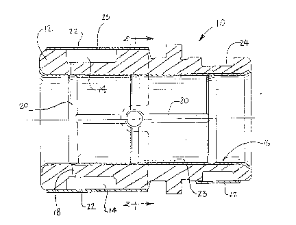
10FIGURE l is a cross-sectional view taken along the
longitudinal center line of the bushing of the present invention;
FIGURF 2 is a cross-sectional view taken along line 2-2 of
FIGURE l;
FIGURES 3-6 illustrate the sequence of steps comprising the
15method of the present invention for the application of a porous .
bearing layer to the internal bearing surface of the bushing; and
FIGURE 7 is a cross-sectional view illustrating a bushing in
exploded view relative to its associated guide post and in which
the bushing includes a sintered bearing layer and the guide post
~ncludes a polymeric solid lubricant layer, which together
provide a superior interface between the bushing and guide post.
.. .
7~
,.
DESCRIPTION OF T3~E PREFERRED EMBODIMENTS
With reference now to FIGURES 1 and 2, the bushing of the
present invention, designated generally as 10, is shown to
include a monolithic body 12, a lubricant cavity or reservoir 14,
an internal bearing surface 16, one or more internal passageways
18, at least one recess 20 in the bearing surface 16, and a cover
, . . .
22 mounted to cylindrical body 12 in order to enclose the
lubricant cavity 14.
The monolithic body 12 is preferably cylindrical and may be
constructed from any one of a variety of materials well known to
those of ordinary skill in the art. A particularly suitable
material is steel. In accordance with one preferred embodiment
of the invention, the machined cylindrical internal surface 16
supports a porous bearing layer 23 which is a compacted and
; 15 sintered material, such as bronze, lead alloy, tin, tin alloy or
other material well known to those of ordinary skill in the art.
The internal surface 16 also includes one or more recesses 20 to
facilitate the distribution of a lubricant. As illustrated in
.j '
! FIGURE 1, the recesses 20 may be positioned circumferentially or
axially or in a network of both. In addition, the recesses may
be angularly disposed or in a "figure eight" arrangement.
In accordance with an important objective of the present
invention the cylindrical body 12 incorporates a lubricant cavity
14, and may optionally include one or more additional lubricant
cavities, such as cavity 24 illustrated in FIGURE 1. Cavity 14
_ g ~
2l~CP76~!3
~ communicates with the internal bearing surface 16 by means of one
. .
, or more passageways 18. Thus, as lubricant is consumed during
i the service life of the bushing, the lubricant stored in cavity
14 will flow from cavity 14 through passageway 18 and along the
recesses 20. In this way, the interface between internal bearing
surface 16 and the external surface of the complementary
guidepost along which the bearing moves will be affectively and
continuously lubricated. Cavity 14 may be most economically
constructed by machining an annular recess in the external
surface of body 12 and thereafter enclosing the machined recess
with a cylindrical cover or casing 22. The casing may be press
. fit or bonded to body 12 in such a manner as to prevent leakage
of lubricant. A small orifice 23 is also formed in casing 22 to
.. . .
, prevent entrapment of air and to permit free flow of lubricant
, 15 from cavity 14 through passageway 18 to the bearing surface 16.
As shown most clearly in FIGURE 2, the bushing 10 may also
1 include an externally accessible filling port 26 having a
., conventional grease fitting 28. Filling port 26 is positioned in
direct communicatisn with one of the recesses 20 a~d through the.
ll 20 network of recesses 20 and passageway 18 is in communication with
? cavity 14. Accordingly, the bushing may be refilled with
~ubricant simply by application of a conventional grease gun to
grease fitting 28. The tool operator will be able to determine
when cavity 14 is filled when excess lubricant begins to
discharge from orifice 23.
, ,
''. :
-- 10 --
Zl~(`'7~83
:.
The method of the present invention is depicted in its
various steps in FIGURES 3-6. As shown in FIGURE 3, a
cylindrical bushing 40 is mounted in a suitable fixture including
base 42, bushing mount 44 and a center pin 46. Next, an
elastomeric plug 48 is located over pin 46 and positioned
concentrically within bushing 40 thereby forming an annular
cavity 47 between its external surface 50 and the internally
machined cylindrical surface 41. The plug 48 is preferably
constructed from a polyurethane elastomer and has a shore
hardness of from about 80 to 120. Most preferably, the plug 48
; has a shore hardness of about 95. Once the plug is properly
positioned to form the annular cavity as just described, a
sinterable particulate 52 is charged or introduced to the cavity
by any of several means well known to those of ordinary skill in
the art. The particulate material may also be any of a number of
well known sinterable powders useful for such purposes. One such
common bronze powder is composed of 90% by weight copper and 10%
by weight tin. Of course, the precise composition of the ~ s
particulate will depend upon the specific applica~ion in which
the bea~ing or bushing is to be used.
; Having filled cavity 47 with a suitable amount of sinterable
~articulatel a press 54 is placed over the bushing and
elastomeric plug. The press includes a center ram 56 which
longitudinally compresses the elastomeric plug 48 thereby causing
its diametric expansion toward the internal cylindrical surface
41 of the bushing 40. As a consequence of this diametric
~ .
' ' ':'
~ 2~ 3
expansion, the particulate is compacted against the internal
~'~ surface 41 to a prescribed density. When -~ompaction of the
particulate is complete the ram 56 is released thereby permitting
~I .
the elastomeric plu~ 48 to return to its original length and
diameter. After removing the elastomeric plug from the bushing
40, the bushing together with its compacted particulate layer is
placed in a suitable sintering oven 58 under conditions well
known to those of ordinary skill in the art and is heated to a
temperature necessary for sintering the particulate into a fused
porous bearing layer 60. Preferably, the layer 60 has a
thickness of about 0.010 to 0.080 inches. The resulting
'' composite bushing exhibits all of the well-recognized advantages
of machined steel bushings with the added advantages associated
with a porous bearing layer on its internal bearing surface.
This layer has a lower coefficient of friction than steel and has
a greater porosity than prior art plated bushings such that
lubricants are more readily retained at the internal bearing
' surface.
As noted earlier it is also desireabie to'apply a polymeric'
'-~ 20 lubrica'nt to the porous bearing layer. Many such polymeric
.,.
lubricants are well known in the art, and any suitable
''`' composition may be used. For example, satisfactory lubricants
are described in United States Patents Nos. 3,882,030; 3,878,113;
4,115,283 and 4,575~429. The disclosures of each of these United
States patents is incorporated herein by reference. Such
; lubricants may be coated or sprayed onto the porous layer and
~; - 12 -
''
.
:'
.
;:
.
~ 376~3
then "cured" by the use of a heated platen. By applying both
heat and pressure to the polymeric lubricant, it will be
impregnated into the surface of the porous bearing layer thereby
enhancing the lubricity of the bearing surface, particularly
during the initial start-up period of the bearing or bushing
production run.
FIGURE 7 illustrates an alternative embodiment of the
pres2nt invention in which the bushing lO includes a porous
bearing layer 60 and the bushingls associated guide post 62
includes a polymeric lubricant layer 64. The guide post 62 is
formed from hardened steel and typically has its external surface
ground to a precise diameter complimentary to the inside diameter
of the bushing. The polymeric lubricant layer may be composed of ~"
any of the lubricants described above and may have a thickness of
less than about 0.0001 inches. This alternative embodiment has
the advantage that it is much easier and less costly to apply the
polymeric lubricant to the external surface of the guide post
rather than to the internal surface of the bushing.
Those skilled in the art will recognize that the bushing of
~20 the pr~sent invention provides an advantage over prior art
bushings in that operator lubrication of the bushing is necessary
mu~h less frequently, in fact, on only an extended periodic
i,.. ..
basis. As a result, such lubrication may be performed during
routine maintenance or changeover of the die set for a new job.
Since lubrication will most likely not be required during the
press run o a specific job, the l~kelihood o a bushing seizing
, '
. , . ~'`.
6~33
during the service period is much less likely. Those skilled in
the art will also recognize that the method of the present
invention is extremely simple and permits the application of a
sintered porous bearing layer to the bushing in a fast and cost-
effective manner.
While particular embodiments of the invention have beendescribed above, it will be obvious to those of skill in the art
that changes and modifications may be made without departing from
the invention in its broader aspects. Therefore, the ob~ect of
the appended claims is to cover all such changes and
modifications which fall within the true spirit and scope of the
invention.
- 14 -
.