Note : Les descriptions sont présentées dans la langue officielle dans laquelle elles ont été soumises.
20~94.2
-1-
PAPER HANDLING APPARATUS
BACKGROUND OF THE INVENTION
The present invention relates to a paper handling apparatus
of the type having a plurality of bins and a chuck unit and a
stapler unit which are movable along the bins, and causing the
stapler unit to bind an end portion of a stack of paper sheets
which have been received from a copier or similar image forming
apparatus, sorted, and then stacked on any one of the bins.
A copier, for example, is operable with an automatic
document feeder (ADF) and a sorter which sorts a plurality of
copy sheets associated with each of a plurality of documents in
order of page and thereby produces a plurality of sets of copies.
More. specifically, while the ADF sequentially feeds the documents
to a reading section of the copier in order of page, the sorter
distributes the resulting copies of each document one by one to
bins thereof. A paper handling apparatus capable of
automatically stapling stacks of paper sheets each being
distributed to respective one of bins in order of page is disclosed
in Japanese Patent Laid-Open Publication (Kokai) No.
5?-63561, for example. This kind of apparatus saves time and
labor necessary for one to take out the stacks of copy sheets
20~"942
-2-
from the individual bins and staple them one by one. In the
prior art apparatus, each paper stack is fully pulled out of the
associated bin and transferred to an elevatable tray to be stap led
there. Another paper stack to be stabled next is pulled out onto
the stapled paper stack and stapled there. By such a sequence,
a pluality of stapled sets of copies are piled up one upon
another. While such a prior art paper handling apparatus
allows the stapled copies to be readily taken out, it needs a
bulky device for pulling out a paper stack onto the tray and a
large exclusive space for the tray, resulting in an increase in
cost and in space for installation.
In the light of the above, there has also been proposed a
paper handliag apparatus capable of automatically stapling
paper stacks sorted into successive bins without increasing the
overall size of the apparatus and the space for installation. This
kind of apparatus has a plurality of bins arranged one above
another, and a stapler and a chuck unit which are movable up
and down along the bins. Paper sheets distributed from a copier
or similar image forming apparatus into each bin are gripped
together by the chuck unit and then pulled out to such an extent
that a portion thereof to be stapled protrude from the bin. In
this condition, the end of the paper sheets is stapled and then
returned to the original position on the bin. This prior art
apparatus, however, has some problems left unsolved, as
enumerated below.
~~a~7942
-3-
(1 ) Paper sheets coming in from a copier or a printer, for
example, are distributed face down to each bin of the paper
handling apparatus in order of page. The stapler, therefore,
drives a staple into such a stack of paper sheets from the
underside of the stack. More specifically, the stapler is moved
from one bin to another while being held in an upside-down
position. It follows that, when the stapler has run out of
staples, one has to replace a staple cartridge from below the
stapler by troublesome manipulations.
(2) The sorting section made up of the bins and sorting
means aad the binding section movable up and down along the
bins for binding paper sheets distributed to the bins are
constructed integrally with each other. This kind of construction
invites an increase in production cost and is, therefore, intrusive
for a user who needs only a simple binding function or does not
need the binding function. The paper handing apparatus having
such a complicated construction needs much time and labor for
maintenance which will be performed at the time of production or
failure. Hence, not only production efficiency and the quality
are lowered, but also the products suffer from scattering.
(3 ) The housing of the paper handling apparatus has a
stapler door which is openable for the replacement of a staple
cartridge, maintenance of the stapler unit and chuck unit, etc.
Besides, the housing has a sorter door and a sorter top cover
for implementing the maintenance and inspection of paper
$00794 2
-4-
transport paths and the removal of a jamming sheet. When any one of such doors
and
covers is opened, a door switch associated with the door is turned off to cut
off the
power supply immediately. If the door is opened while the stapler is in
operation, a
motor driving the stapler is immediately turned off to interrupt the stapling
operation.
This often causes a staple to stop the stapler or to be bent itself or locks
the stapler
with a paper stack bit into the stapler.
SUMMARY OF THE INVENTION
The present invention provides a paper handling apparatus which facilitates
manipulation for maintenance and other purposes.
The present invention can also provide a paper handling apparatus which allows
one to readily replace a staple cartridge even with a stapler of the type
which can drive
a staple from the underside of a paper stack.
The present invention can also provide a paper handling apparatus which is
simple in construction, easy to produce and maintain, and inexpensive, despite
that it
has a sorting section and a binding section. '
Also the present invention can provide a paper handling apparatus which
eliminates the interruption of the stapler's operation and other similar
accidents, when
any one of the doors of a housing is opened while a stapling operation is
under way.
The present invention can also provide a generally improved paper
handling apparatus.
In accordance with the present invention, a paper handling apparatus comprises
a plurality of bins arranged one above another;
a sorting section comprising distributing and sorting means for distributing
and
sorting paper sheets to said plurality of bins; and
X00794 2
-5
a binding section comprising means for driving the binding section up and
down along said plurality of bins, said binding section comprising a stapler
for binding
stacks of paper sheets distributed to said plurality of bins;
said binding section being removable from said sorting section,
wherein said binding section is constructed as a unit and is mountable and
dismountable from said sorting section in a direction in which paper sheets
are driven
out into said sorting section.
Also, in accordance with the present invention, a paper handling apparatus
comprises:
a housing;
a plurality of bins arranged one above another;
stapling means movable up and down along said plurality of bins for stapling
an end portion of a stack of paper sheets which have been received from an
image
forming apparatus in any one of said plurality of bins;
a stapler door provided on said housing at the front of a movable range of
said
stapling means; and
another door provided on said housing,
said stapling means continuing, when said another door is opened when said
stapling means is performing a stapling operation, said stapling operation
until said
stapling operation completes.
Further, in accordance with the present invention, a paper handling apparatus
comprises:
a plurality of bins arranged one above another;
X00794 2
-6-
stapling means movable up and down along said plurality of bins for stapling
an end portion of a stack of paper sheets which have been received from an
image
forming apparatus in any one of said plurality of bins; and
moving means for moving said stapling means between a substantially
horizontal stapling position for stapling the stack of paper sheets and a
staple supply
position for supplying staples to said stapling means.
BRIEF DESCRIPTION OF THE DRAWINGS
The above and other objects, features and advantages of the present invention
will become more apparent from the following detailed description taken with
the
accompanying drawings in which:
Fig. 1 is a sectional side elevation schematically showing a specific
construction
of a prior art paper handling apparatus having a sorter with a stapler;
Fig. 2 is a plan view of a bin, a stapler and a chuck unit included in the
apparatus of Fig. 1;
Fig. 3 is a perspective view showing a specific construction of the stapler of
the
prior art apparatus;
Fig. 4 is a perspective view of the prior art apparatus shown in Fig. l;
Figs. 5 to 9 are views showing a stapler unit representative
aoo X94 2
_7_
of an embodiment of the paper handling apparatus in accordance
with the present invention in a sequence of stages for replacing a
staple cartridge;
Fig. 10 is a front view of a sorting unit applicable to a
preferred embodiment of the paper handling apparatus in
accordance with the present invention;
Fig. 11 is a front view of a binding section also applicable to
the embodiment of the present invention;
Fig. 12 is a front view which is the combination of Figs. 10
and 11;
Fig. 13 is a view of a binding section representative of an
alternative embodiment of the present invention and which is
shown in an uncoupled position;
Fig. 14 is a plan view showing the binding section of Fig. 14
in a coupled position;
Fig. 15 is a plan view showing the binding section of Fig. 13
in the uncoupled position;
Fig. 16 is a front view of the illustrative embodiment
combined with a copier;
ZO Fig. 17 is a flowchart demonstrating a sequence of steps for
moving an elevator to a leading bin when any one of the
illustrative embodiments performs a stapling operation;
Fig. 18 is a flowchart representative of a stapling operation
of any one of the illustrative embodiments;
Fig. 19 is a flowchart showing a procedure for moving the
200'7942
_8_
stapler of any one of the illustrative embodiments between bins;
and
Fig. 20 is a flowchart showing how the stapler of any one of
the illustrative embodiments is controlled when any one of doors
and covers of a housing is opened.
2~~"~942
-9-
DESCRIPTION OF THE PREFERRED EMBODIMENTS
To better understand the present invention, a reference will
be made to a prior art paper handling apparatus, shown in
Fig. 1. The apparatus shown in Fig. 1 is implemented as the
prior art apparatus disclosed in previously mentioned Japanese
Patent Laid-Open Publication No. 57-63561 by way of example.
As shown, the apparatus has a sorter which includes a housing
1. A discharge tray 2 is located at the uppermost position in the
housing 1. A plurality of, twenty in this specific construction,
bins 3 are arranged one above another at predetermined
intervals below the discharge tray 2. The discharge tray 2 and
bins 3 are parallel to each other and extend obliquely upward
toward the outside of the housing 1. A 'paper transport path 5
terminates at a paper inlet 4 at which paper sheets from a
copier, for example, will arrive. A selector in the form of a
pawl 6 is located on the paper transport path 5 in the vicinity of
the upper end of the apparatus. The selector 6 is movable to
select either one of a path extending toward the discharge tray 2
and a paper transport path 7 which extends vertically along the
paper inlet side of the bins 3. Transport roller pairs 8 are
arranged one above another and at suitable intervals on the
vertical paper transport path 7. A deflector also implemented as
a pawl 9 and a discharge roller pair 10 are located in a
particular position on the vertical path 7 where they face the
inlet of any one of the bins 3. A discharge roller pair 11 is
2Q9'~942
-lo-
positioned on the path which terminates at the discharge tray 2.
The transport rollers and discharge rollers mentioned above are
driven by a motor 12. Shafts 15 and 16 carrying pulleys 13A
and 13B and pulleys 14A and 14B, respectively, are journalled to
the framework of the apparatus. The upper and lower shafts 15
and 16 are located at the front of the group of bins 3, i. e. , at
the viewer's side with respect to the sheet surface of Fig. 1. The
pulleys 13A and 14A and the pulleys 13B and 14B are vertically
aligned with each other. A motor 17 is drivably connected to
the lower shaft 16. A belt 18A is passed over the aligned pulleys
13A and 14A, while a belt 18B is passed over the aligned pulleys
13B and 148. A bracket 19 is anchored at opposite ends thereof
to one run of the belts 18A and 18B which is located at the front
side. The bracket 19 is inclined by the same angle as the bins
3. A stapler unit 2 0 and a chuck unit 21 are mounted on the
underside of the bracket 19. Guide rollers are rollably mounted
on opposite sides of the bracket 19, while channel-like guide
rails 22 for guiding the guide rollers are located at the front of
the bins 3. Specifically, the rollers are rollably receive in the
guide rails 22 which extend over substantially the entire height of
the sorter.
A paper sheet driven out of the copier and reached the paper
sheet 4 advances along the paper transport path 5. When an
ordinary paper discharge mode is selected, the selector 6 steers
the paper sheet toward the discharge tray 2. On the other
~oo~s~
-11-
hand, when a sorter mode (sorting in order of page) or a stack
mode (sorting page by page) is selected, the selector 6 steers
the paper sheet to the vertical paper transport path 7. The
deflectors 9 and discharge roller pairs 10 each being associated
with respective one of the bins 3 are actuated in matching
relation to the sorter mode or the stack mode, whereby paper
sheets are distributed to the individual bins 3. As shown in
Fig. 2, an abutment 3A extends upward from the paper inlet end
of each bit 3, while a retractable bin fence 23 extends upright
from the front end of each bin 3. Hence, paper sheets
distributed to any one of the bins 3 are sequentially stacked by
being abutted against the abutment 3A and bin fence 23 by the
inclination of the bin and a presser, not shown.
Assume that a staple mode for stapling paper stacks loaded
on the individual bins is selected. Then, as shown in Fig. 2, the
motor 1 ? is energized to move the bracket 19 which carries the
stapler unit 20 and chuck unit 21 therewith sequentially to the
successive bins 3. After the bracket 19 has been located at any
one of the bins 3, a chuck 24 included in the chuck unit 21 is
extended toward the bin 3 until it reaches a notched portion 3B
of the bin 3. The chuck 24 chucks the stack at the notched
potion 3B and then pulls it out to a position which is indicated by
a dash-and-dot line in Fig. 2. At this instant, the bin fence 23
is urged by the end of the paper stack to its retracted position.
: A front left portion of the paper stack having been pulled out of
__
~ ~'942
-12-
the pin 3 is received in a recess of the stapler unit Z0. In
response to a staple signal, a solenoid associated with the
stapler unit Z 0 is energized to activate the stapler 2 0 so as to
staple the stack at one corner 25 of the latter. Subsequently,
the chuck 24 is again extended toward the bin 3 to return the
stapled paper stack into the bin 3, opened to release the stack,
and then retracted to a position indicated by a solid line in the
figure. Thereupon, the bracket 19 is moved to another bin.
Referring to Fig. 3, a stapler 100 built in the stapler unit 20
is shown. The stapler 100 is loaded with a stapler cartridge
104. Staples 40 are tied together in a band configuration by a
thin tape with their opposite portions to form bent legs being
straightened. The band of staples 40 is rolled up and received in
the staple cartridge 104. Biasing means, not shown, maintains
the . leading staple 40 in a position where it faces a stapling
position 42. When a motor 43 is energized by an electric signal,
a stapling section 103 located above the stapling position 42
bends opposite ends of the leadin8 staple 40 of the staple band in
the form of a letter U and presses it downward. As a result,
the legs of the staple 40 penetrate a paper stack and are then
bent inward while being guided by recesses which are provided
oa a receiving section 45 located below the stapling position 42.
Subsequently, the motor 43 is turned off while the stapling
section 103 is raised away from the stapling position 42. When
a near-end sensor 46 senses the last staple 40 on the tape, a
~~0'~~~2
-13-
near-end signal is produced to turn on a display for urging one
to replace the staple cartridge 104. The near-end sensor 46
may be implemented by a reflection type photoelectric sensor.
2Q0'~~~2
-14-
A number of paper sheets driven out of a copier, printer or
similar image forming apparatus are often distributed face down
to each bin of a paper handling apparatus in order of page. To
bind such stacks of paper sheets by a stapler, it is necessary
that the stapler drives a staple into the paper stack from the
underside of the stack. More specifically, the stapler is moved
from one bin to another while being held in an upside-down
position. It follows that, when the stapler has run out of
staples, one has to replace a staple cartridge from below the
stapler by troublesome manipulations.
The sorting section made up of the bins and sorting means
and the binding section movable up and down along the bins for
binding paper sheets distributed to the bins are constructed
integrally with each other, as stated above. This kind of
construction invites an increase in production cost and is,
therefore, intrusive for a user who needs only a simple binding
function or does not need the binding function. The paper
handing apparatus having such a complicated construction needs
much time and labor for maintenance which will be performed at
the time of production or failure. hence, not only production
efficiency and the quality are lowered, but also the products
suffer from scattering.
As shown in Fig. 4, the housin8 1 of the sorter has a stapler
door 5 0 which is openable for the replacement of a staple
cartridge, maintenance of the stapler unit and chuck unit, etc.
200'~9~2
-15-
The stapler door 5 0 is positioned on the front end of the housing
1 as viewed from the operator's side and extends over a movable
range of the stapler unit and chuck unit. Besides, the housing 1
has a sorter door 51 at the front end thereof and a sorter top
cover 5 2 at the top for implementing the maintenance and
inspection of paper transport paths and the removal of a
jamming sheet. A copier, printer, sorter or similar office
equipment is constructed such that when any one of such doors
and covers is opened, a door switch associated with the door is
turned off to cut of the power supply immediately so as to
deenergize motors. This is successful in enhancing safety
operations. Regarding a sorter in which a stapler is driven by a
motor for binding paper stacks as stated previously, opening the
door causes all the motors to be stopped. If the door is opened
while the stapler is in operation, the motor driving the stapler is
turned off immediately to interrupt the stapling operation. This
often causes a staple to stop the stapler or to be bent itself or
locks the stapler with a paper stack bit into the stapler.
Preferred embodiments of the paper handling apparatus in
accordance with the present invention will be described which is
free from the drawbacks particular to the prior art as discussed
above.
Referring to Figs. 5 to 9, there is shown a specific
construction of a stapler unit included in the illustrative
embodiment. The stapler unit, generally 20, is mounted on the
~o~~s~
-16-
underside of a bracket 19 which is movable up and down along a
group of bins 3, as shown in Figs. 1 and 2. The position of the
stapler unit 20 is opposite to the position shown in Fig. 3 as
viewed in the vertical direction. While a stapler built in the
stapler unit 20 shown in Figs. 5 to 9 is constructed and operated
in the same manner as the stapler 100 shown in Fig. 3,
individual members constituting the stapler are somewhat
different in configuration.
As shown in Fig. 5, the stapler unit 200 positioned upside
down has a support 98 affixed to the bracket 19, and a stapler
10 0 rotatably mounted on the base 9 8 by a shaft 9 9. The
stapler 100 is made up of a base 101 rotatably supported by the
shaft 99, a body 102 rigidly mounted on the base 101, a
stapling section 103, and a replaceable staple cartridge 104. A
pawl 105 and a lever 10? are rotatably mounted on the support
98 by shafts 106 and 108, respectively. A pin 109 is studded on
the base 101 of the stapler 101 in such a manner as to engage
with the pawl 105 in an operative position shown in Fig. 5. One
end of the lever 107 is connected to one end of the pawl 105.
gpecifically, an elongate slot 110 is formed through the lever 107
while a pin 111 is studded on the pawl 105 and received in the
slot 110, so that an angular movement of the lever 107 may be
transmitted to the pawl 105. Of course, the slot 110 and pin
111 of the lever 107 and pawl 105, respectively, may be
replaced with each other. A spring 112 is preloaded between the
~oo~s4z
-17-
pawl 10 5 and the support 9 8 to constantly bias the pawl 10 5 to
a position where it engages with the pin 109. In the position
shown in Fig. 5, the pawl 105 is engaged with the pin 109 to
hold the stapler 100 in the operative position. When a person
raises the lever 10? to a position shown in Fig. 6, the pawl 105
releases the pin 109. As a result, the stapler 100 is rotated 90
degrees about the shaft 99 by gravity or by hand to a staple
supply position which is shown in Fig. 7.
A lever 113 is rotatably connected to the base 101 of the
stapler 100 by a shaft 118. A pin 114 is studded on the free end
of the lever 113 and received in a cam slot
(or cam groove)
115
which is formed through the
support 98. A locking recess
116 is
formed in the support 98 and the cam slot
contiguous with 115.
In the staple supply position shown in Fig. the pin 114 drops
7,
into the locking recess 116 resulting in stapler 100 being
the
locked in the staple supply position. Whenthe lever 107
is
released after the stapler 100 has moved away from the
operative position as stated above, the l 105 regains
paw the
original position under the action of the spring 112 and,
therefore, the lever 107 in Fig. ?. In
is restored as shown the
position shown in Fig. 7, the lever 107 is located below the
locking recess 116 while the pin 10 7 is located above the lever
107. In such a staple supply position, the stapler 100 is almost
protruded to the outside of the side bracket of the sorter to
facilitate the replacement of the staple cartridge 104.
_. 2~~'~94~
-18-
After the replacement of the staple cartridge 104, the lever
107 is raised to a position shown in Fig. 8. Then, the pin 114
is urged upward by the upper edge of the lever 107 and thereby
released from the locking recess 116, whereby the stapler 100 is
allowed to rotate freely about the shaft 99. As soon as the lever
107 is released, the pawl 105 is restored by the spring 112.
The stapler 100 is rotated counterclockwise as viewed in the
figures to the operative position either by hand or by suitable
returning means. At this instant, as shown in Fig. 9, the pin
109 abuts against the pawl 105 and, by cooperating with a slant
of the pawl 105, urges the pawl 105 outward to a position
indicated by a phantom line in the figure. Then, the pin 109 is
again engaged with the pawl 105 by the spring 112.
As stated above, the stapler 100 is movable between the
operative position for ~ stapling a paper stack and the staple
supply position for replacing a staple cartridge, facilitating the
replacement of a .staple cartridge. Easy replacement of a staple
cartridge is further promoted because the stapler 100 is tiltable
in the up-and-down direction to the staple supply position where
it protrudes to the outside.
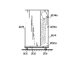
Referring to Figs. 10 to 12, a paper handing apparatus
embodying the present invention is shown which is loaded with
the stapler unit 20 having the above construction. As shown, a
sorting unit 203 is securely mounted on a mount 202 which is
provided with casters 201. The sorting unit 203 has multiple
~0079~ 2
-19-
bins 203a which are arranged one above another. A space 202a
is available on the mount 202 at the right of the sorting unit 203
for mounting a binding section 204 which has a binding
implement 204a. The binding section 204 may be mounted in the
space 202a and combined with the sorting unit 203, as shown in
Fig. 12.
Figs. 13 to 16 show an alternative embodiment of the
present invention. As shown, a sorting unit 213 is fixed on a
mount 212 having casters 211 while a binding section 214 is
fixed on a mount 216 having casters 215. The mounts 212 and
216 may be abutted against each other to combine the sorting
unit Z 13 and the binding section 214. Then, in the event of
maintenance, the mount Z 16 with the binding section 214 will be
moved away from the mount 214 with the sorting unit 213. In
Fig. 15, the reference numeral 217 designates a guide rod. In
Fig. 16, alphabet A designates a copier body. Such a binding
unit . removable from a sorting unit not only broadens the
selectable range of products but also enhances efficient
production and maintenance.
An alternative embodiment of the present invention will be
described in detail with reference to Figs. 1, 2 and 4 showing
the sorter 1.
As shown in Fig. 4, the stapler door 50 is positioned on the
front wall of the housing of the sorter 1 as viewed from the
operator's side and extends over the movable range of the
~0079~ 2
-20-
stapler unit 2 0 and chuck unit 21. The sorter door 51 and
sorter top cover 5 Z are respectively positioned on the front wall
and the top wall of the sorter housing in order to facilitate the
maintenance and inspection of various components and structural
elements as well as the removal of a jamming sheet. A sensor
or door switch, not shown, is associated with each of the doors
50, 51 and 52 for sensing open and closed positions of the door.
The illustrative embodiment is controlled as follows.
Specifically, when the staple door 50 is opened as sensed by the
sensor while a stapling operation is under way, the stapling
operation is stopped immediately. However, when a door other
than the staple door, i. e. , the sorter door 51 or the sorter top
cover 52 is opened while a stapling operation is under way, the
stapling operation is continued until it completes. When the
sorter door 51 or the sorter top cover 52 is opened while the
chuck 24 (Fig. 2) of the chuck unit 21 is moved forward, the
chuck motor associated with the chuck 24 is turned off and no
stapling operations are performed. Further, when the sorter
door 51 or the sorter top cover 52 is opened while the chuck unit
24 is moved backward with a paper stack, the stapling operation
is continued until that paper stack has been stapled.
As stated above, when a door other than the stapler door 50
is opened during a stapling operation, the stapling operation is
continued until it completes. This is successful in prevening the
stapler from being stopped by a staple. Stopping the stapling
-21- aoom~ 2
operation when the stapler door 50 is opened is desirable from
the safety operation standpoint.
A specific operation of the illustrative embodiments of the
present invention will be described with reference to Figs. 17 to
20.
To facilitate an understanding of the operation of the present
invention, the stapling operation of the prior art paper handling
apparatus shown in Fig. 1 will be described first. In the prior
art apparatus implemented as the sorter 1, stacks of paper
sheets distributed to the bins 3 are sequentially stapled from the
top to the bottom. When a staple start command from an image
forming apparatus is received, an elevator (bracket 19, Fig. 1 )
loaded with the stapler unit 2 0 is shifted to the bin which is
loaded with a paper stack to be stapled first.
-22- $00794 2
Specifically, as shown in Fig. 17, a particular bin at which
the stapling operation should begin is determined in response to
a staple start command. The sorter 1 has twenty bins 3 which
are divided into a first or upper block and a second or lower
block each having ten bins 3. First, which of the first and
second blocks is loaded with paper stacks to be stapled is
determined. If the first block ins loaded with such paper stacks,
"1 + number of bins with stapled stacks" is inputted in a leading
bin counter which is indicative of a bin at which the stapling
operation should begin. At the same time, a shift command for
commanding a shift to the leading bin is delivered. The words
"number of bins with stapled stacks" mean the number of bins
whose paper sheets have already beea stapled and is indicated by
a stapled stack counter. This counter is reset to 0 when all the
paper stacks have been bound by a single set of stapling
operations or when the stapling mode is replaced with another
mode. The stapled stack counter is not cleared in response to a
jam signal, a cover/door open signal, and a staple interrupt
command from the image forming apparatus. Hence, when the
next staple start command arrives, the stapling operation is
resumed from the uppermost one of the bins with non-stapled
stacks by skipping the bins with stapled stacks.
In response to the shift command, an elevator motor
(motor 17, Fig. 1 ) is turned on to lower the stapler 20. As the
2 5 stapler 2 0 is lowered, a bin address sensor sequentially senses
-23- ~ 0 ~ 7 9 ~ 2
exclusive pieces each being associated with respective one of the
bins 3. When the bin address sensor is just turned on, the
leading bin counter is decremented by 1. As soon as the leading
bin counter reaches 0, the shift command is interrupted and the
elevator motor is turned off. As a result, the stapler is stopped
at the position where the leading bin is located. Then, 1 is
inputted in a staple sequence counter to start a stapling
operation.
Referring to Figs. 18A and 18B, a sin8le staplin8 procedure
will be described. When the stapler reaches the leading bin, the
staple sequence counter is incremented from 0 to 1. When the
staple sequence counter is 1, the chuck motor is energized to
move the chuck 24 (Fig. 2) of the chuck unit 21 forward. When
a pre-chuck sensor responsive to the end of the forward
movement of the chuck unit 21 is turned on, the chuck unit 21 is
brought to a stop while the staple sequence counter is
incremented to 2. When the staple sequence counter is 2, , the
chuck solenoid is turned on to cause the chuck 24 to grip a paper
stack and the staple sequence counter is loaded with 3. When
the staple sequence counter is 3, the current state is held for 0. 2
second and, on the lapse of 0. 2 second, the staple sequence
counter is incremented to 4. When the staple sequence counter is
4, the chuck motor is turned on to move the chuck unit 21 to the
home position. When a post-chuck sensor responsive to the
2 5 arrival of the chuck unit 21 at the home position is turned on,
20~J'~94~
-24-
the chuck unit is again brought to a stop and the staple sequence
counter is incremented to 5. When the staple sequence counter is
5, whether the output of a paper sensor is indicative of the
presence of a paper stack. If it indicates the presence of a
paper stack, the stapler performs a stapling operation. When
the end of the stapling action is detected, the staple sequence
counter 6 is incremented to 6. If a paper stack is absent, the
stapling operation is skipped.
When the staple sequence counter is 6, the chuck solenoid is
deenergized, the stapled stack counter is incremented, and a
shift motor is energized. Then, the stapled stack counter is
compared with a reserved stack memory indicative of the total
number of bins storing paper stacks to be stapled. If the former
equals the latter, the staple sequence counter is reset to 0 and
the stapling procedure is terminated. Thereafter, the elevator
motor 1? is turned on to return the stapler unit 21 to its home
position. If the stapled stack counter is smaller than the
reserved stack counter, the staple sequence counter is
incremented to 7. When the staple sequence counter is 7, the
current state is held for 0. 3 second and, on the lapse of 0. 3
second, a command is delivered for moving the stapler to the
next bin on the basis of a subroutine shown in Fig. 19.
In Fig. 19, when the stapler shift command is delivered, the
elevator motor 1? is turned on while a timer is started. When a
predetermined period of time expires as counted by the timer,
2oa~~4z
-25-
the staple sequence counter is incremented to 1 to start a
stapling operation for the next bin. When an elevation position
sensor is turned on, the elevator motor is turned off to end the
shift of the stapler between the bins. In the illustrative
embodiment, the stapling operation for the next bin begins about
100 milliseconds before the end of movement of the stapler to
that bin, thereby reducing the stapling time. The procedure
described above is repeated until the stapled stack counter equals
the reserved stack counter. So long as the stapler door 50,
sorter door 51 and sorter top cover 52 are closed, the stapling
operation is continued.
Fig. 2 0 shows a sequence of steps which are executed when
any one of the doors and cover of the sorter housing is opened
during a stapling operation. As shown, when the stapler door
5 0 is opened while a stapling operation is under way, the staple
sequence counter is reset to 0 and all the loads are turned off.
When the sorter door 51 or the sorter top cover 52 is opened
with the stapler door 51 being closed (hereinafter referred to as
a state 1 ) , the following processing is executed.
2 0 In the state 1, if the chuck 2 4 of the chuck unit 21 (Fig. 2 )
is moving forward, the staple sequence counter is reset to 0 and
the chuck motor is deenergized. In the state 1, if the chuck has
already moved forward and 0. 2 second has not expired yet after
the turn-on of the chuck solenoid, the staple sequence counter is
reset to 0 and the chuck solenoid is deenergized. In the state 1,
,-- 200~'94~
-26-
if the chuck of the chuck unit 21 has already moved forward and
0. 2 second has expired after the turn-on of the chuck solenoid
(hereinafter referred to as a state 2 ) , the following sequence
procedure is executed.
In the state 2, if the chuck of the chuck unit 21 is moving
backward, the staple sequence counter is incremented to 4 and
the operation is continued. In the state 2, if the chuck of the
chuck unit 21 has already moved backward and a stapling
operation is under way, the staple sequence counter is
incremented to 5 and the operation is continued. In the step 2,
if the chuck of the chuck unit 21 has already moved backward
and a stapling operation has ended, the staple sequence counter
is reset to 0 and all the loads are turned off. Further, in the
state 1, if the elevator motor is in rotation, the staple sequence
counter is reset to 0 and all the loads are turned off.
In response to a staple interrupt command from the image
forming apparatus, the sequence of steps which occur in
response to opening of the sorter door 51 or the sorter top cover
52 as described above is also executed. Specifically, a stapling
operation is completed, and then the elevator is raised to the
home position.
While the illustrative embodiments of the present invention
have concentrated on a sorter with a stapler shown in Figs. 1 to
4, the present invention is of course applicable to other various
kinds of sorters in which the drive of a stapler, the grip and
2G~"~942
-27-
pull-out of a paper stack from a bin and the return of the paper
stack are executed electrically by a predetermined sequence. For
example, each of the upper and lower chucks of the chuck unit
may be movable. The pull-out and return of a paper stack may
each occur at a lower speed at the start and end of a movement
than at an intermediate portion.
In summary, in accordance with the present invention, a
stapler is movable between an operative position for stapling a
paper stack and a staple supply position for replacing a staple
cartridge, thereby facilitating the replacement of a stapler
cartridge. Especially, the stapler is tiltable downward to the
staple supply position where it protrudes to the outside of a side
bracket of a sorter, further promoting the ease of replacement
of a staple cartridge. A binding unit is removable from a
sorting unit to broaden the selectable range of products and to
enhance efficient production and maintenance. Further, when a
door .or a cover other than a stapler door is opened while a
stapling operation is under way, the stapler is not deactivated
until the stapling operation completes. This eliminates various
accidents such as the stapler being stopped by a staple.
Various modifications will become possible for those skilled
in the art after receiving the teachings of the present disclosure
without departing from the scope thereof.