Note : Les descriptions sont présentées dans la langue officielle dans laquelle elles ont été soumises.
4 7 9 - S F
2C~07~76
METHOD AND APPARATUS FOR DETECTING FLAWS
ON INTERNAL WALLS OF FLUID TUBES
BACKGROUND OF THE INVENTION
The present invention relates to a method and an
apparatus for detecting flaws on the internal wall of tubes
and piping having an open end which is plugged by a
detachable seal plug to accommodate therein a high pressure
fluid and, more particularly, to a method and apparatus for
detecting flaws on the internal wall of the piping used
particularly in a pressure tube of a nuclear reactor, which
is subject to a periodical in-service inspection (ISI)
according to the rules. The present invention provides a
new method and a new apparatus for automatically detecting
ultrasonic flaw, particularly suitable for a pressure tube
of a pressure tube type nuclear reactor, although not
limited thereto.
Pressure tubes steam drums, pressure vessels piping and
the like, herein after referred to as pressure tubes for
only simplicity, used in a nuclear reactor such as a
pressure tube reactor, a light water reactor, and a fast
reactor accommodate therein a high pressure fluid during
operation. Further, since the pressure tubes and the like
to be inspected are exposed to a high radiation environment
both internally and peripherally, the inspection personnel
is strictly prohibited to stay near the radiation
2C~07~3~;
environment and the inspection is carried out by an
automatic remote controller so as to protect the inspection
presonnel at the time of the in-service inspection. At
present, a remote controlled, automatically operated
ultrasonic flaw detector is inserted into the pressure tube
to be inspected to examine the pressure tube from the inside
thereof. Conventionally inspections by an ultrasonic flaw
detection method have been carried out on the internal wall
thereof while suspending the operation of the reactor during
the in-service period.
The flaw inspection for these pressure tubes are
proferably carried out at short intervals on a repetitive
basis with the reactor in operation for mainternance control
purposes. However, this entails a suspension of the
reac~or operation at every inspection, with the result that
the availability factor of nuclear power generation and
other services are reduced.
Thus, any attempt to inspect the interior of the
pressure tubes, through whch high temperature of about 280~C
and high pressure of about 70Kg/cm2 cooling water is flowing
and which is exposed to a high radiation dose (a neutron
flux of about 1014n/cm2 sec. and a gamma ray of about 109
R/H), by inserting an inspecting tool such as an ultrasonic
detecting probe causes the problem in that the inspecting
tool is damaged in a very short period of time.
2C~0~6
SUMMARY OF THE INVENTION
An object of the present invention is to provide a new
method of detecting flaws on the internal wall of pressure
tubes of a nuclear reactor.
Another object of the present invention is to provide a
new apparatus for detecting flaws on the internal wall of
pressure tubes of a nuclear reactor.
A further object of the present invention is to provide
a method and an apparatus which permit to detect flaws on
the internal wall of pressure tubes and other piping
mechanism which accommodate therein a high pressure fluid
for the pressure tube reactor which is in operation under
the severe conditions that cooling water of high temperature,
high pressure and high radiation dose is flowing therein.
According to the present invention, there is provided a
method of detecting flaws on the internal wall of pressure
tubes and the like comprising the steps of tightly and
hermetically connecting the openable end of the pressure
tube to a sealable container filled with a fluid such as
nonreactive liquid or high pressure gas with the openable
end being closed by a seal plug, releasing the seal plug
from the open end of the pressure tube, inserting a hollow
tube into the pressure tube through the open end,
irradiating the radiation beam onto the internal wall of the
pressure tube through the hollow tube to thereby transmit
and obtain a reflected signal of the radiation beam, and
detecting the reflected signal to thereby detect flaws based
-- 3 --
2~)07~7~
upon a change in the reflected signal.
According to the present invention, there is provided an
apparatus for detecting flaws on the internal wall of
pressure tubes and the like comprising a hermetically
sealable container filled with a fluid such as nonreactive
liquid or high pressure gas, a connector for releasably and
hermetically connecting an open end of the pressure tube to
the container, a seal plug mounting device in the container
for mounting and demounting a seal plug to and from the open
end of the pressure tube, a hollow tube having a sealed top
end, a window adjacent to the top end, and means for
transmitting an irradiating beam through the window to the
inner wall of the pressure tube and transmitting a reflceted
signal of the irradiating beam to a bottom of the hollow
tube, insertion device for releasably inserting the hollow
tube into the pressure tube through the connector. The
hollow tube has a beam source connected to the bottom end
thereof for irradiating the radiation beam and a detector
for detecting the reflected signal which has been
transmitted.
In the present invetion, when the pressure tubes to be
inspected are those of the cooling tube reactor which is in
operation with cooling water flowing through the cooling
tube, the substatial elements such as the windows, hollow
tube and the devices for transmitting the irradiating beam
and the reflected signal are made of a material which is
resistant to a high temperature of 280~C or higher, a high
pressure of about 70Kg/cm2 G or higher, and a high radiation
dose with a neutron flux of about 1014n/cm~ sec and a gamma
ray of about 109R/H or larger.
In the method of the present invention, almost
simultaneously with the step of tightly connecting the open
end of the pressure tube to the sealable container by means
of a preferable connecting device such as a tubular
connector, either a liquid which is nonreactive with the
cooling water or a gas which is similarly nonreactive and
has a pressure of about 70Kg/cm2 G which is as high as the
pressure of the cooling water , is filled in the container.
The fluid filled in the container may preferably be the cold
water, i.e., water of ambient temperature.
Examples of the irradiating beam transmitter may include
a reflecting mirror and an optical fiber disposed at a
predetermined position within the hollow tube.
By contrast, the reflected signal transmitter can be
selected depending upon the type and nature of reflected
signal. In the case that a surface reflected signal of the
radiation beam is visually detected, a laser camera is used,
and in case that absorption or emission of light by the
internal wall of the pressure pipe is detected from the
surface reflected signal or the reflected signal of the
radiaction beam, a reflecting mirror can be used so that it
is disposed adjacent to the window of the hollow tube.
The detector for detecting the reflected signal can be
selectred depending upon the type and nature of detected
2~7~3~;J6
signal. Various types of sensor, and displays such as
color CRTs and recorders such as oscilloscopes connected to
the sensors can be used. If necessary, a microcomputer
unit may also be connected between the sensors and the
display or recorder, e.g., to eliminate the noise from the
detected signal.
In an embodiment of the invention, reElecting mirrors
are used as the irradiating beam transmitter and the
reflected signal transmitter respectively disposed at
different positions within the hollow tube, and the beam
source includes a first source having a heating pulse laser
oscillator for irradiating the radiation beam, and a second
source having a continuous light laser oscillator for
irradiating the detecting beam. The first and second
sources are hermetically connected to the bottom end of the
hollow tube so that the detecting beam is irradiated
adjecent to the irradiating beam. The heat pulse laser
beam and the continuous light laser beam are irradiated and
transmitted from the bottom end of the hollow tube onto the
internal wall of the pressure tubes through one of the
reflecting mirrors and the window, and reflected to thereby
produce a vibration, which is caused by the reflection of an
ultrasonic wave on a flow position, and the vibration is
transmitted on the other reflecting mirror as a change in
intensity of reflection of the continuous light laser beam.
The ultrasonic wave mentioned above is generated by rapid
heating of the internal wall by irradiation of the heating
pulse laser thereon.
BRIEF DESCRIPTION OF THE DRAWING
Figure 1 is a diagram illustrating an embodiment of a
flaw detecting device according to the present invention,
Figure 2 is a schematic sectional view of a pressure
tube to be detected, for use in a pressure tube reactor in
operation,
Figure 3 is a schematic sectional view of the pressure
tube before flaw inspection showing that a fuel element and
a radiation shielding plug are removed for flaw inspection,
Figures 4 and 5 are schematic sectional views of the
flaw detecting device, showing the process of the flaw
detection according to the present invention, and
Figure 6 is partially enlarged sectional view of the
flaw detecting device according to the invention and a
pressure tube to be detected.
PREFERRED EMBODIMENTS OF THE INVENTION
The present invention will be described in more detail
with reference to a preferred embodiment thereof.
Each of 224 pressure tubes 1 which are arranged in
paralled sidewise relation in the core of a pressure tube
reactor are placed under a high radiation dose (a neutron
flux of about 1014n/cm2 sec and a gamma ray of about
-- 7
X1~0~ 6
109R/H). During the operation of the reactor, each
pressure tube 1 generally accommodates therein a fuel
element 2 and a radiation shielding plug 3 as shown in
Figure 2, and this bottom open end is sealed by a releasable
seal plug 4. Through a pipe 5 connected to a side end of
the pressure tube, there flows cooling water of high
temperature (about 280~C) and high pressure (about 70Kg/cm2
G) into the pussure tube 1 as shown by arrow A, which is
then discharged via pipe ~ conneced to the upper end after
cooling the fuel element 2 in the pressure tube 1, as shown
by arrow B.
In order to detect flaws on the internal wall of the
pressure tube 1, the seal plug 4 is released and the fuel
element 2 and the radiation shielding plug 3 are pulled out
from the pressure tube 1 by a fuel exchanger (not shown)
which is known in the art, and then the bottom open end is
again sealed with the seal plug 4, as shown in Figure 3.
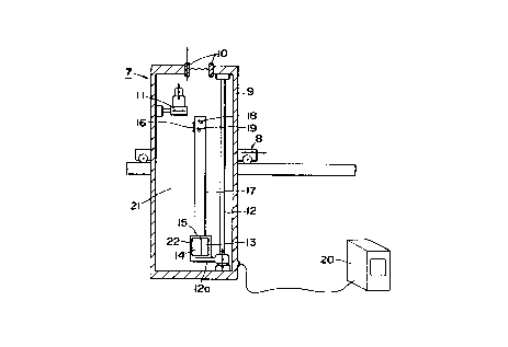
In Figures 1 and 4, the flaw detecting device, which is
generally indicated by reference numeral 7, has a transfer
car 8 for moving the detecting device 7 to a predetermined
position just felow the pressure tube 1, and a hollow
container 9 containing therein the cold water 21 has at
its upper end opening a tubular connector 10 which is
upwardly movably connected to the opening of the container
so that is is releasable in the upward direction (Fig.
1). The connector 10 has an outer circumferential furface
made of, e.g., a titanium alloy or a heat resistant rubber
~o
material that allows the outer circumferential surface to be
tightly and hermetically fitted to the inner circumferential
suriace of the bottom open end 1a of the pressure tube 1.
As shown in Figure 4, the connector 10 is releasably
connected to the bottom open end 1a of the pressure tube
by a suitable moving device (not shown) which utilizes water
pressure, pneumatic pressure, hydraulic pressure, or/ther
like.
On one side of the hollow container 9 interior, there
is provided a seal plug loading machine 11 capable of
detaching and attaching the seal plug 4 from and to the
bottom open end of the pressure tube 1 by, e.g., a rotating
device using female and male screw threads engagement with
the seal plug. The seal plug loading machine 11 can be
extended horizontally and vertically so that its uppermost
part can be engaged with the seal plug 4 through the
connector 10, as shown in Figure 4.
On the other side of the hollow container 9 interior,
there is provided a lifting machine 12 which has a
vertically movable table 12a horizontally disposed below the
connector 10 so that the table 12a is moved in the vertical
direction by a lifting stroke using a chain, screw, and the
like. On the lifting table 12a, a heating pulse beam
irradiating source 13 including a heat pulse laser
oscillator, a detecting beam irradiating source 14 including
a continuous light laser oscillator, and a detecting beam
sensor 15 are fixed. On top of those devices 13, 14 and
Z~3'7~ 6
15, a hollow tube 17 of a sutable metal is vertically fixed
at a position so that the sealed top end thereof can be
aligned with and passed through the connector 10. The
hollow tube 17 is sealed or closed on the top end and has a
window 16 on the upper side end close to the top end. Both
the hollow tube 17 and the window 16 are made of a material
which is resistant to high temperature (about 280~C) and
high presure (about 70Kg/cm2) cooling water which flows
through the pressure tube 1 under a high radiation dose (a
neturon flux of about 1014n/cm2 sec and a gamma ray of about
109R/H). In this case, it is preferred that the heating
pulse laser oscillator of the heating pulse beam irradiating
source 13 includes laser oscillators based on such laser
systems as semiconductor laser, yttrium-aluminum-garnet
laser, carbon dioxide laser and glass laser, and the
continuous light laser oscillator of the detecting beam
irradiating source 14 incluses laser oscillator based on
such laser systems as helium-neon laser, argon laser, and
krypton laser.
The hollow tube 17 is further provided, in the interior
thereof, with reflecting mirror 18, 19 made of a material
which is resistant to high temperature of about 280~C. A
heating pulse beam from the source 13 is projectd from the
bottom end of the hollow tube 17 as shown by reference
character X in Figure 6 and a detecting beam from the other
source 14 is projected, as shown by Y in Figure 6, adjacent
to and along with the heating pulse beam from the source 13.
-- 1 0 --
37~
The heating pulse beam and the detecting beam are reflected
on the reflecting mirror 18 and 19, respectively, and then
irradiated out of the hollow tube 17 through the window 16.
The reflected beam of the detecting beam (Y) is then passed
into the hollow tube 17 through the window 16 and is
reflected on the reflecting mirror 19 so that the reflected
beam is received and detected by the detecting beam sensor
15 which is disposed on the bottom end of the hollow tube
17. The window 16 is made of a quartz glass and the mirrors
18, 19 are made of a quartz glass having a reflecting
surface of a metal film or a surface polished metal.
A dry gas such as air or nitrogen is filled in the
hollow tube 17, which is sealed and kept hermetic by a
watertight enclosure 22 which contacts the external
circumferential surface of the bottom end of the hollow tube
17 and hermetically covers the heating pulse beam
irradiating source 13, the detecting beam irradiating source
14 and the detecting heat sensor 15. The detecting beam
sensor 15 is electrically connected to an oscilloscope 20
which is externally provided to the hollow container 9 so as
to allow the signal detected by the sensor 15 to be observed
on the display of the oscilloscope 20.
Next, the method of the flaw detection will be
explained, the pressure tube1 which is sealed by the seal
plug 4 at the bottom open end where as the bottom side pipe
allows the flow of cooling water as shown by arrow A in ~ig.
3.
- 11 -
73~7~
First, the container 9 is moved by the transfer car ~ so
that: the connector 10 is aligned to a position just below
the bottom open end of the pressure tube 1 to tightly
connect the bottom open end of the pressure tube 1 to the
container 9 by the connector 10. Thereafter, as shown in
Figure 4, the seal plug 4 is removed from the pressure tube
1 by operating the seal plug loading machine 11 to
accommodate the seal plug 4 within the hollow container 9.
The contaniner 9 is so tightly filled with the cold water
that it is unlikely that the cooling water flowing from the
bottom side pipe into the pressure tube 1 wi.ll flow into the
hollow container 9 when the seal plug 4 is removed. At
the same time, the heat conductivity of the cold water
filled in the hollow container 9 is so small that the heat
conduction from the high temperature (about 280~C) cooling
water can effectively be shielded and, accordingly, the
interior condition of the container 9 can be maintained
almost uncharged before and after the removal of the seal
plug 4.
Then, the hollow tube 17 is lifted upward by operating
the lifting machine 12 and inserted into the pressure tube 1
through the connector 10 as shown in Figure 5.
Thereafter, the heating pulse beam irradiating source 13,
the detecting beam irradiating source 14, and the detecting
beam sensor 15 are operated.
With reference to Figure 6, as shown by reference
character X, a heating pulse laser beam of the heat pulse
- 12 -
2~)~73'~6
beam irradiating source 13 is projected from the bottom end
to the interior of the hollow tube 17, reflected on the
reflecting mirror 18, and irradiated,via the window 16, onto
the internal wall of the pressure tube 1 through which the
cooling water is flowing. Upon irradiation of the heating
pulse laser beam, the internal wall portion of the pressure
tube 1 is subjected to a thermal expansion due to the rapid
heating, and an ultrasonic wave is generated at the internal
wall portion and propagated over the surface and interior of
the pressure tube 1. If there is a flaw over the surface
or interior of the pressure tube 1, the ultrasonic wave is
reflected on that flaw portion and thus the pressure tube is
slightly vibrated. This reflection-induced vibration of
the pressure tube 1 becomes more conspicuous as the flaw is
located closer to the source or origin for generating the
ultrasonic wave, i.e., the portion on the internal wall of
the pressure tube 1 which has been irradiated by the heating
pulse laser beam. The reflection-induced vibration of the
pressure tube 1 is converted into a reflected light beam
whose intensity corresponds to the degree of the
reflection-induced vibration, by the continuous light laser
beam shown by reference character Y in Figure 6. The
continous light laser beam is projected from the source 14
to a position of the pressure tube which position is
adjacent to the irradiation portion of the heating pulse
laser beam, and the reflected light beam is irradiated onto
the detecting beam sensor 15 disposed on the bottom end of
Z~7~
the hollow tube 17 after it is reflected on the reflecting
mirror 19 via the window 16. The reflected light beam is
subjected to a photoelectric conversion by the detecting
beam sensor 15 and then observed on the display of the
oscilloscope, wherein the detected peak corresponds to the
reflection-induced vibration which succeeds the vibration
derived from the irradiation of the heating pulse laser beam
onto the pressure tube 1 with a delay of, e.g~,
microseconds.
After the flaw detection has been completed in the
manner as described above, the pressure tube 1 is returned
to the original position as shown in Figure 2 in which the
fuel element 2 and the radiation shielding plug 3 are
accommodated in the pressure tube 1, which is then plugged
by the seal plug 4 again, by reversely following the
aforementioned procedure for the detection.
In the embodiment described above, a suitable rotating
device can be provided in the hollow tube 17 to allow the
internal wall of the pressure tube 1 to be detected with
one full rotation by circumferentially rotating the hollow
tube 17. If the piping apparatus such as the pressure
tube 1 to be inspected includes only one tube in the plant
such as the pressure vessel in a light water reactor, it may
also be possible to substitute the transfer car 8 with a
suitable fixed apparatus.
According to the present invention, the outflow of the
high pressure fluid such as the cooling water flowing
- 14 ~
2(~ 3~6
through the pressure tube is prevented by a nonreactive
liquid or high pressure gas which is filled in the hollow
container, at the time of removing the seal plug from the
bottom open end of the piping apparatus as the pressure
tube, and after the seal plug has been removed for the
purposes of detecting flaws of the pressure tube.
Accordingly, the detection of the internal wall of the
pressure tubes and the like can be achieved with the high
pressure fluid being accommodated therein without suspending
the operation of the nuclear reactor, thereby allowing the
reactor to be continuously operated for a longer period of
time, which contributes to improvement in the availability
factor of power generation and the like services without
imparing the safety of the reactor. It is further
possible to conduct the detection at short intervals with
the nuclear reactor in operation, so that even small,
initial abnormalities of the pressure tubes can be detected
to permit earlier and immediate actions to be taken against
such abnormalities.
Additionally, the detecting elements inserted into the
high pressure fluid as the cooling water in the pressure
tube are made of a suitable material which withstands the
high pressure fluid as well as the heat conducted through
the high pressure fluid and, on the other hand, the other
detecting elements are always kept isolated from the high
pressure fluid and entirely enclosed within the nonreactive
liquid or nonreactive, high pressure gas atmosphere so that
2C~7~76
the heat conducted through the high pressure fluid are
shielded. Especially, when the cooling water is used for
the nonreactive liquid as in the embodiment disclosed
herein, the thermal conductiity thereof is so small that the
heat conducted through the high pressure fluid ti.e.,
cooling water in the illustrated embodiment) can be shielded
thereby efficiently. Thus, the method and apparatus of the
present invention can be applied with a stable performance
for a long period of time.
- 16 -