Sélection de la langue

Search

Sommaire du brevet 2008093 

Énoncé de désistement de responsabilité concernant l'information provenant de tiers

Une partie des informations de ce site Web a été fournie par des sources externes. Le gouvernement du Canada n'assume aucune responsabilité concernant la précision, l'actualité ou la fiabilité des informations fournies par les sources externes. Les utilisateurs qui désirent employer cette information devraient consulter directement la source des informations. Le contenu fourni par les sources externes n'est pas assujetti aux exigences sur les langues officielles, la protection des renseignements personnels et l'accessibilité.

Disponibilité de l'Abrégé et des Revendications

L'apparition de différences dans le texte et l'image des Revendications et de l'Abrégé dépend du moment auquel le document est publié. Les textes des Revendications et de l'Abrégé sont affichés :

  • lorsque la demande peut être examinée par le public;
  • lorsque le brevet est émis (délivrance).
(12) Demande de brevet: (11) CA 2008093
(54) Titre français: DISPOSITIF POUR FABRIQUER DES ARTICLES CREUX EN PLASTIQUE
(54) Titre anglais: DEVICE FOR PRODUCING HOLLOW SHAPED PLASTIC ARTICLES
Statut: Réputée abandonnée et au-delà du délai pour le rétablissement - en attente de la réponse à l’avis de communication rejetée
Données bibliographiques
(51) Classification internationale des brevets (CIB):
  • B29C 45/00 (2006.01)
  • B29C 45/17 (2006.01)
(72) Inventeurs :
  • PETERSON, CHRISTER CALEB INGEMAR (Suède)
(73) Titulaires :
  • AKTIEBOLAGET ELECTROLUX
(71) Demandeurs :
  • AKTIEBOLAGET ELECTROLUX (Suède)
(74) Agent: SMART & BIGGAR LP
(74) Co-agent:
(45) Délivré:
(22) Date de dépôt: 1990-01-18
(41) Mise à la disponibilité du public: 1990-08-09
Licence disponible: S.O.
Cédé au domaine public: S.O.
(25) Langue des documents déposés: Anglais

Traité de coopération en matière de brevets (PCT): Non

(30) Données de priorité de la demande:
Numéro de la demande Pays / territoire Date
8900440-2 (Suède) 1989-02-09

Abrégés

Abrégé anglais


A B S T R A C T (Fig. 1)
This invention relates to a device for producing hollow shaped plastic
articles by injection molding the device comprising a nozzle (10) having a firstinlet opening for melted plastic from the injection molding machine and a secondinlet opening for a gas, means for directing gas into the melted plastic and
an outlet opening for the gas and for the melted plastic, the outlet opening
via a gate being connectable with a mold space. The second inlet opening com-
municates via a conduit (28) with a gas accumulator (29) having a constant
volume and in which the gas has a mainly constant pressure. Said connection
also has a variable throttle (32) by means of which the gas flow through the
conduit can be adjusted.

Revendications

Note : Les revendications sont présentées dans la langue officielle dans laquelle elles ont été soumises.


C l a i m s
1. Device for producing hollow shaped plastic articles by an injection molding
procedure the device comprising a nozzle (10) with a first inlet opening (18)
for melted plastic from an injection molding apparatus and a second inlet ope-
ning (22) for a gas, means (19) for directing the gas into the melted plastic and
an outlet opening (15) for the gas and the melted plastic the outlet opening
via a gate being connectable with a mold space, c h a r a c t e r i z e d in that
the second inlet opening (22) via a conduit (28) communicates with a gas accumu-lator (29) having a constant volume and in which the gas has a mainly constant
pressure and that said conduit has a variable throttle (32) by means of which
the gas flow through the conduit can be adjusted.
2. Device according to claim 1, c h a r a c t e r i z e d in that the con-
duit (28) also comprises a valve (33) between the gas accumulator (29) and the
nozzle (10).
3. Device according to claim 2, c h a r a c t e r i z e d in that it comprises
an electric control circuit for the valve (33), the control circuit comprising
control means (48, 49) for opening the valve (33) a predetermined time after
that the injection of the melted plastic into the nozzle (10) has been initiated.
4. Device according to claim 3, c h a r a c t e r i z e d in that the time
delay is 0.05-10 sec.
5. Device according to claim 3, c h a r a c t e r i z e d in that the control
means comprises a time relay (49) for maintaining the valve in an open position
during a predetermined time which is 1-1000 sec.
6. Device according to any of the preceding claims, c h a r a c t e r i z e d
in that it is provided with a branched off conduit (393 extending from the con-
duit (28) at the outlet side of the throttle (32) to the inlet side of the accumu-
lator (29) for recollecting 3 part of the gas which flows through the throttle.
7. Device according to claim 6, c h a r a c t e r i z e d in that the branched
off conduit (39) is provided with a booster for increasing the pressure of the
recollected gas.
8. Device according to claim 6 or 7, c h a r a c t e r i z e d in that the
branched off conduit (39) is provided with a valve (40) which is closed during
the stage of the procedure when plastic and gas is ejected into the mold and
during a part of the cooling time.

9. Device according to claim 8, c h a r a c t e r i z e d in that the valve (40)of the branched off conduit (39) is opened by a time relay (50) when the
valve (33) of the conduit is closed.
10. Device according to any of claims 6 - 9, c h a r a c t e r i z e d in that
the branched off conduit is provided with a check valve (43).

Description

Note : Les descriptions sont présentées dans la langue officielle dans laquelle elles ont été soumises.

Device for produclng hollow shaped plastic articles 20~8~:393
Thls Invention relates to a device for producing hollow shaped plastic
articles by inJection molding and the device comprises a nozzle having a first
lnlet openlng for melted plastic from an Injection moldlng mlachIne and a secondinlet opening for a gas, means for directing the gas Into the melted plastlc andan outlet opening for the gas and the melted plastic, the outlet opening being
connectable to a mold via a gate.
It is previously known to produce hollow shaped plastic articles according
to what has been described above. DE-OS 2 4~51 580 describes a device in which
melted plastic is ejected through a nozzle to a mold the nozzle comprlslng a
central outlet for a gas. The gas and the melted plastic are transferred to the
mold slmultaneously which means that the melted plastic surrounds the gas
and forms a shell which solidifies agalnst the walls of the mold. As an e~campleof suitable gases nitrogen Is mentioned. In order to force che gas into the melted
plastlc a cylinder is used to whlch the gas is transferred from a suitable source.
The cylinder is via a conduit and a valve connected to a central channel in the
nozzle. The cylinder is filled with gas, the gas is compressed by means of the
piston and the gas is then introduced into the melted plastic.
A similar method is described in ~P 127 961 according ~o which the cy-
linder which is used to force the gas into the melted plas~ic also serves as a
measuring device for the gas in order to adapt the gas volume to the article
being produced. The piston has a stroke which is variable and which can be
set on a predetermined value corresponding to the gas volume whlch is used.
After fllling the cylinder the gas supply is cut off and the gas i6 compressed
by moving the piston forwards. At a certain pressure the valve is opened and
the gas is tr~nsferred to the melted plastic.
The devices described above offer among o~her things a possibility to
avoid sinkings i.e. Iocal deformations which are formed when producing thick-
-walled plastic articles. Moreover a better economy is achleved compared to
conventional methods since the consumption of plastic material is reduced at
~he same as the method means an non-negliable veight reduction of the artlcle
produced.
The purpose of this invent{on is to create a device for ad~usting the flow
of gas into the nozzle which is more simple then the arrangernents which are
previosly knswn. Another purpose is to create a possib~lity to recollec~ the
.
:: .
: . . ~ ..... .

~ :3~D~q~3~:~
gas or at lease a part of the gas which is us~d duri~g the procedure. Thls is
achleYed wleh a device haYirlg the characrerl6tlcs men~loned in the clalms.
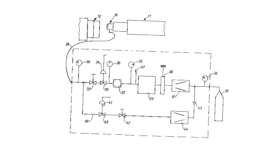
An embodiment of the ~nvention wlll know be descrlbed wlth reference
eo the attached drawing where Plg. 1 diagrammaticly shows a d~vice accordlng
to the present invention whereas Flg.2 shows a ver~lcal section through the
nozzle through which the plastic and the gas Is dellvered to the mould and Flg. 3
shows the electric control unic for the equipment.
As appears from Fig. 1 the device comprises a nozzle 10 to whlch a conven-
tlonal plastic inJection machine 11 is associated. The nozzle Is in the usual way
movable to abut a tool 12 comprising a mold space with which the nozzle com-
municates via a gate in the tool.
As appears from Figure 2 the nozzle 10 comprlses a front mounted hat
like part 13 in which a central outlet channel 14 with an outlet 15 is arranged.In the part 13 there is an insert 16 with an axial through channel 17 having an
Inlet opening 18 for plastic, the channel 17 being coaxial with the outlet
channel 14, the two channels partly belng shaped as trunca~ed cones ~oining
each other. In the middle of the channel 14 and 17 there is a pipe 19 whlch
;~
is a part of the insert 16 and which extends from the insert into the outlet
channel 14 and ends at the center of the outlet opening 15. The pipe 19 ae its
other end is formed as a radial channel in the Insere 16 and continues as a
sleeve 20 which is directed radially and on which a nipple 21 is fastened. The
channel in the nipple 21 and in the sleeve 20 has an inlet opening 22 for gas
which is transferred to ~he nozzle.
The nozzle also has a rear part 23 with a valve body 24 which normally
abuts a seat 25 and which dlvides and seals a chamber Z6, In whlch the mel~ed
plastic Is present, from the inlet opening I8 In ehe nozzle. The valve body 24
can by means of a device, noe shown in detail, be moved axially so that the
melted plastic flows from the chamber 26 to the inlet openlng 18 of the nozzle.
The front part I3 and the rear part 23 of the nozzle are connected to each otherby means o~ locking members 27.
The gas inlet opening 22 of the nozzle 10 communlcates via a conduit 28
with a gas accumulator 29 having a fixed volume in which the gas is presen~
under a comparatively high pressure. This gas accumulator is connected to a
gas booster 30 i.e. a pressure increasing device which is fed with gas from a
gas source 31 i.e. a gas bottle through a continuation of the conduie 28. The
gas booster 30 thus creates a mainly constant pressure in the gas accumula-
tor 29. Preferably nitrogen Is used but also other gases or gas mixtures can
be used.
. .
2 --

The condult 28 is provlded wlth a varlable throttle 32 by means of whlch
the gas flow to the nozzle can be set wlth great accuracy at cestaln values
corresponding to the produced artlcle. In Its most slmple version th~ throttle
comprises a needle valve by means of Yvhich the flow-through-area o~ the con-
duit 28 can be changed in a simple way by adJus~ing ehe posltlon of the valve
body wlth the aid of a screw havlng a fine thread. The condult 28 also comprisesa valve 33 which is activated and deactivated by means of pnellmatlc, hydraullc
and/or electric means 34 with the aid of an electric control uni~ which will
be described below.
Between the gas accumulator 29 and ~he valve 33 there is a pressure
control device 35 by means of which a sllltable pressure can be choosen in the
part of ~he conduit 28 which is situa~ed to the left of ~he pressure control
-- device 35. The condui~ also is provided with pressure sensing devices 36 for
observing and controlling the pressure in the different parts of ehe condult 28.There also is a safe;y valve 37 and a dehumidlfier 38 for the gas.
In order to make it possible to recover and recycle the gas which flows
out into the conduit ~8 through the throttle 32 there ls a branched off condult 39
which is connected the conduit 7g to the left of the throttle 32 and between
the booster 30 and the gas source 31. This conduit 39 is provided wi~h a valve 40
activated and deactivated by pneumatic, hydraulic and/or electric means 41
with the aid of said control unit. The conduit 39 also ls provided with a
!throttle 42, a check valve 43 and a booster 44 increaslng the pressure of the
gas in the conduit to the lefr of the booster 44 to the same pressure as in the
conduit between the booster 30 and the gas source 31.
The control unit, Fig. 3, has a maln switch 45 connecting the maln supply
with a transformer 47 the secondary slde of whlch is connecred eo a swltch
on delayed relay 48 which recelves an imput sigDal from ehe in~ec~ion mouldtng
machine when the valve body 24 is moved so tha~ the melted plaseic i6 e~ected
into the nozzle. The delay can be set between O.OS and 10 sec. The relay 48
connects the secondary side of the transformer wlth a time relay 49 and thls
relay actlvates the means 34 for opening the valve 33. The ~Ime selay can be
set to keep the valve open for 1-1000 sec. When the tlme relay ~9 after a
predetermined time swi~ches back to its original posl~ion and the valve 33 is
closed another time relay 50 i6 activated for a prede~ermined period. Thls relaya activates the means 41 for openlng the valve 40.
The control unil: aiso is provlded wlth a switch 51 and an electrlc clrcuit
~or opening the valve 33 manually in order to empty the conduit and the gas
channels by a gas flow through the nozzle if something should clog the channels.

The devlce operates ln the following way. Normally the valve 33 In the
condu~t 28 Is closed the gas booster 30 keeplng a malnly con6tant pressure
In the gas accumulator 29 the pressure b~elng about 100-1000 bar. The valYe
body 24 abuts rhe seat 25 in the nozzle whlch means thae ~he melted plastic
is prevented from enterlng the nozzle. When a pla~tlc artlcle Is to be for~ned
the nozzle 10 is moved to abue the mold 12 and the valve body 24 ~6 moved
to the left In the Plgure whereby the melted plastlc by means of rhe pressure
in the Dozzle which normally Is about 500-1000 bar Is pressed lnto the channel 17
in the nozzle. The switch-on delayed reLly 48 will then be drawn after the
predetermlned time. Thereby the ~Ime relay 49 is actlvated so that current
Is ~ransferred to the means 34 whlch actlYates the valve 33 so that It opens.
This means that gas in the gas accumulator 29 flows throu~h the condult 28
and through the throttle 32. By ad~usting the throttle an adaptlon of the gas
flow through the nozzle 10 occurs so ~hat the velocity of ~he Inflowlng gas Intothe nozzle mainly corresponds to the flow-through velocley of the melted plastlc.
The gas wlll thus flow ~hrough the pipe 19 and flow out at the outlet openlng 15of ~he nozzle so ~hat a central gas core Is form~d whlch Is surrounded by the
plastic. Because of the switch-on delay of the valve a plastlc plug Is formed
a~ the frone preventing the gas from breaking through the pla6tlc and cause
holes in Its surface layer. The gas then presses the plastic towards the walls
of the mold. When the valve body 24 then is seturned to Its or~glnal posit~on
the melted plastic will cease from flowlng through the nozzle the communlcat~on
howeve~ besng maintained between the gas accumulator 29 and the mold 12
becau6e the relay 49 remaln~ irs l~s drawn posltion durlng the tlme which has
~een set. The communication between the accumulator 29 and the mold 12
16 preferably maintained durlng the complete injection moidiDg procedure v~th
the exception of the Introduction phase as ~ell as it Is malntalned afterward~
during the coollng period. When ~he relay 49 Is deact~vated curren~ flow~ to
the relay 50 thereby establlshlng and electrlc connectlon ~o the means 41 for
opening the valve 40 so that gas in the condult 28 ~o ehe left of the valve 33
and in the nozzle 10 and mold 12 flows through the condu~ 39 and is compressed
by the boo~ter 49 to the ~ame pressure as In ~he ga~ source 31. After a
predete~mined time tbe relay 50 deactlvates the means 41 thereby closing ehe
valYe 40 again.
It should be mentloned tha~ It sometlmes Is necessary to use a check
valve 52 In the gas sup~ply channel of the nozzle 12 preventlng gas from flowingback fro~m the mold since there ~s a r{sk ehat pleee~ of plas~c follow the back
flowing stream aDd clog the channel. Thls of cour~e re~ult~; In a reduct{on o~

Ebe amount o~ ga6 whlch 1~ recollected but usually the amoun~ of ga6 whlch
16 enclosed by the condult 2g Is large compared to the ~mount of gas whlch
16 enclosed In the article belng praduced whlch mean~ that the ratlo of recotlec-
tlon 1~ sufflclent.

Dessin représentatif
Une figure unique qui représente un dessin illustrant l'invention.
États administratifs

2024-08-01 : Dans le cadre de la transition vers les Brevets de nouvelle génération (BNG), la base de données sur les brevets canadiens (BDBC) contient désormais un Historique d'événement plus détaillé, qui reproduit le Journal des événements de notre nouvelle solution interne.

Veuillez noter que les événements débutant par « Inactive : » se réfèrent à des événements qui ne sont plus utilisés dans notre nouvelle solution interne.

Pour une meilleure compréhension de l'état de la demande ou brevet qui figure sur cette page, la rubrique Mise en garde , et les descriptions de Brevet , Historique d'événement , Taxes périodiques et Historique des paiements devraient être consultées.

Historique d'événement

Description Date
Inactive : CIB de MCD 2006-03-11
Le délai pour l'annulation est expiré 1998-01-20
Demande non rétablie avant l'échéance 1998-01-20
Inactive : Abandon.-RE+surtaxe impayées-Corr envoyée 1997-01-20
Réputée abandonnée - omission de répondre à un avis sur les taxes pour le maintien en état 1997-01-20
Demande publiée (accessible au public) 1990-08-09

Historique d'abandonnement

Date d'abandonnement Raison Date de rétablissement
1997-01-20
Titulaires au dossier

Les titulaires actuels et antérieures au dossier sont affichés en ordre alphabétique.

Titulaires actuels au dossier
AKTIEBOLAGET ELECTROLUX
Titulaires antérieures au dossier
CHRISTER CALEB INGEMAR PETERSON
Les propriétaires antérieurs qui ne figurent pas dans la liste des « Propriétaires au dossier » apparaîtront dans d'autres documents au dossier.
Documents

Pour visionner les fichiers sélectionnés, entrer le code reCAPTCHA :


Pour visualiser une image, cliquer sur un lien dans la colonne description du document (Temporairement non-disponible). Pour télécharger l'image (les images), cliquer l'une ou plusieurs cases à cocher dans la première colonne et ensuite cliquer sur le bouton "Télécharger sélection en format PDF (archive Zip)" ou le bouton "Télécharger sélection (en un fichier PDF fusionné)".

Liste des documents de brevet publiés et non publiés sur la BDBC .

Si vous avez des difficultés à accéder au contenu, veuillez communiquer avec le Centre de services à la clientèle au 1-866-997-1936, ou envoyer un courriel au Centre de service à la clientèle de l'OPIC.

({010=Tous les documents, 020=Au moment du dépôt, 030=Au moment de la mise à la disponibilité du public, 040=À la délivrance, 050=Examen, 060=Correspondance reçue, 070=Divers, 080=Correspondance envoyée, 090=Paiement})


Description du
Document 
Date
(aaaa-mm-jj) 
Nombre de pages   Taille de l'image (Ko) 
Dessins 1990-08-08 3 62
Abrégé 1990-08-08 1 35
Revendications 1990-08-08 2 51
Description 1990-08-08 5 218
Dessin représentatif 1999-07-28 1 14
Taxes 1996-01-16 1 64
Taxes 1995-01-02 1 59
Taxes 1994-01-04 1 56
Taxes 1992-12-10 1 55
Taxes 1991-12-17 1 45