Note : Les descriptions sont présentées dans la langue officielle dans laquelle elles ont été soumises.
2~ 40
Attachment for rail vehicles
The present invention relates to an attachment suitable for
use in conjunction with rail vehicles, and more especially
with passenger cars possessing UIC-approved traction-and-
buffing gear and inter-vehicle communication systems whose
parting planes are forced by pre-tension to slide past each
other. Such communication systems furthermore, when not
coupled, extend beyond the plane of their respective buffer
heads.
On European railroads, most rail traffic is hauled by
locomotives. The vehicles used in this traffic possess at
both ends resiliant traction-and-buffing gear normally
comprising a screw-type coupling and two side buffers. In
addition, passenger cars used throughout the world are fitted
with inter-vehicle communications systems that meet the ~ `
requirements of UIC Directive 561.
Such communication apparatuses consist, for example, in
accordance with DIN 25 625, Page 1, essentially of a
resiliant, backwardly-pushable communication bridge and a
pneumatically-sprung rubber connection that surrounds the
crossover gap on the top and sides. The underside of such
communication apparatuses is designed to permit the required
degree of mobility in the event both of pronounced lateral
relative shifting between rail vehicles and of height
deviations between rail vehicles, even when the buffers are
fully compressed.
In addition, international railroading agreements (e.g. sect.
33 RIC) provide for the safety of railwaymen performing
coupling and decoupling tasks. In this context, section 25 of
the EBO (Railway Construction and Operating Directives)
stipulates the existence of a "Berne Clearance" between
stationary parts on rail vehicles, with the exception of the
signal mountings.
``, ' ' ~ .~ . ' . , ,. :
.... - ~ . , - ' :
- ~\
2 Z0~137~0
Experience has shown that the use of such communication
devices, particularly in the face of ever-increasing track
speeds, does little to prevent the incursion of air, cold,
dirt and snow. Such systems moreover allow the compressive
shocks, which in train collisions or during tunnel runs are
intensified by high speed, to propagate unchecked over the
inter-vehicle communication zone and into the rail vehicles
themselves.
A system designed to redress such deficiencies has been
disclosed in DE-OS 3 514 978 and retains the UIC bellows-type
connector. In this arrangement, a communication protector
mounted from the inside of both vehicles completely surrounds
the crossover gap and both communication bridges.
i
The disadvantage attending this prior art system stems from
the installation of the communications protector on the inside
of the rail vehicle and its mounting between two already-
coupled rail vehicles. The preparation or mere existence of
such a communications protector, which can only be regarded as
an unnecessary extra piece of equipment, poses a number of
operational problems, particularly whenever through coaches
are to be made up or train sections rehooked. In addition,
the protector that surrounds all sides of the communications
system may be exposed to damage if pronounced lateral relative
shifting of the rail vehicles causes the side buffers of one
of the vehicles to come into contact with the communication
bridge of the other vehicle and either push such bridge
backwards a distance corresponding to the length and
resiliency of such buffer or, in the event that the bridge is
higher than the buffer, lift the bridge up slightly.
DE-OS 35 23 939 discloses another design for the
communications systems of passenger railcars fitted with UIC-
approved traction-and-buffing devices, aimed at reducing the
propagation of shock waves through such systems. Proposed is
' ' , ' ' . . '' ' ~ ' ''. ' ' ',:
. ~ . . ; , . . '. ' . J
~ ZO(~7~0
a communications bellows consisting of two profile halves of
M-shaped cross section, one end of which connects to the
vehicle body, while the other end of such system is fitted
with a slip rail. This arrangement provides for the
surrounding of the crossover zone on the top and on both
sides. The parting plane of the communications bellows
extends, when the vehicles are not coupled, beyond the buffer
plane, which means that when the two vehicles are coupled,
their already-stressed bellows meet and then slide over each
other without transferring shock waves, if supported, for
example, by pressurized gas dampers.
A disadvantage of this prior art system becomes apparent when
a passenger car fitted with the above-mentioned communication
apparatus is coupled with a rail vehicle not possessing a
similar device, one example of which is a locomotive. Because
in such a situation the parting plane of the communication
apparatus stands out in front of the buffer plane of the host
vehicle, an attempt to couple such vehicle can lead to a
collision with the buffers of the other rail vehicle, which in
this case are the buffer heads of a locomotive.
Collisions can, in the first place, occur by virtue of the
static height differentials normally existing between such
rail vehicles, but are far more likely to occur as a result of
dynamic motion caused by differences in vertical suspension or
as a result of lateral relative shifting between rail
vehicles, which occurs during S-curve running.
Experience has also shown that differences in buffer hardness
between two coupled vehicles whose communication apparatuses
slide on top of each other in order to prevent propagation of
shock waves, may also lead, in the zone of the communication
bridge, to collisions between the communication apparatus and
the buffers of the opposing vehicle.
An analogous situation arises if an attempt is made to couple
: . . .
. . . .:
:: .. - . . . : .: : : . .
.. :.- - ,, , ~ .:
Z~(~87~
the above-mentioned communication apparatus to a UIC-approved
bellows device whose rubber bellows exhibit relatively low
stiffness.
Finally, it is known that the slip faces of communication
apparatuses, which in order to stem shock propagation slide
over each other, have to be relatively broad in the transverse
direction in order to provide for a degree of overlap which,
for example, during S-curve travel, is sufficient to
accomodate maximum relative lateral shifting between two rail
vehicles. Such broad slip faces have a tendancy, when one
edge of a buffer is worn down--which may, for example occur
during repeated travel over tight curves -- to collide with
the signal mounting of a passenger car fitted with a UIC-
approved bellows-type communication device~
The object of the present invention is thus the provision of a
means of permitting the elimination of the disadvantages
attending the prior art communication apparatuses.
According to the invention there is provided an attachment
suitable for use in conjunction with rail vehicles or more
particularly with passenger cars possessing UIC-approved
traction-and-buffing devices and communication devices whose
parting planes are able to slide against each other by virtue
of pre-tension and which when relaxed extend beyond the plane
of the buffer head belonging to the same rail vehicle, whereby
said attachment comprises buffer deflecting means designed to
be attached in mirror-reversed manner to both left and right
hand sides of a communication device for the purpose of
protecting the components of said communication device from
collisions with the buffers of the other rail vehicle.
Fitting of the proposed device on passenger cars featuring
UIC-traction-and-buffing gear possessing prestressed
communications systems capable of damping shock waves arising
from high speed rail travel, whose parting planes are capable
.. ... . . . : , , ,
2~3~8~0
of sliding over each other and furthermore when decoupled
project beyond the plane of the buffer head of the vehicle to
which they belong, prevents such communication devices from
colliding with the buffers of other rail vehicles to which
they are to be coupled.
Collisions with the buffers of other rail vehicles are avoided
by use of the proposed device, whenever a passenger car fitted
with the proposed device couples with a vehicle which,
although possessing UIC-approved traction-and-buffing gear,
lack a communication apparatus, which may be the case if a
locomotive is to be coupled to the passenger car.
One advantage of the proposed device is that the parting plane
of a communication device which projects beyond the buffer of
the vehicle to which it belongs is, when the buffers of both
vehicles press together, pulled far enough back by the
backward travel of the buffer of the rail vehicle to which it
belongs, that the Berne Clearance, required for safe coupling,
is maintained.
The special design of the proposed device permits the
existence of a Berne Clearance even under unfavourable
conditions, for example during lateral relative shifting of
the buffers of two rail vehicles, which can occur during
travel over S-curves.
Even in cases wherein two opposing buffers exhibit different
hardnesses, the proposed device prevents collisions between
the communication device and the opposite buffer in the zone
of the communication bridge.
The proposed device is also used to advantage whenever a
passenger car featuring a communication apparatus projecting
beyond a buffer head plane is to be coupled with a vehicle
possessing a UIC-approved bellows communication apparatus.
'' : , : . ::
- ~ .,: : .
- .
-
. ~ , .
:
- ~ :
37~0
Schematically illustrated are:
Figs. 1 and 2 are a frontal view and a plan view of a proposed
bu~fer deflecting device;
Fig. la is the blank of the proposed buffer deflecting
device in accordance with Figs. 1 and 2,
Figs. 3 and 4 are a frontal view and a plan view of a proposed
device arranged between a rail vehicle buffer
and a communication device extending beyond the
plane of the buffer head located on the car to
which such device belongs.
i
Figs. 5 and 6 are a frontal view and a plan view in accordance
with Figs. 3 and 4, however with a buffer that
has been worn down by the action of the opposing
buffer.
Figs. 7 and 8 are a frontal view and a plan view in accordance
with Figs. 3 and 4, however with an opposing
buffer that has shifted to the edge of its
maximum lateral shifting range.
Fig. 9 is a further design variation of the proposed buffer
deflecting device, in perspective.
A proposed attachment possessing a buffer deflecting device 1
in accordance with Figs~ 1, la and 2 features on its front a
plurality of adjoining surfaces 2, 3 and 4, each of which
possesses, in accordance with its function, a different shape.
For the same reason, surface areas 2, 3 and 4 meet each other
at obtuse angles.
The blank, which contains the incipient shape of a buffer
deflecting device 1 in accordance with Figs. 1 and 2, lies in
one plane. The tongue-shaped withdrawal surface 2 is bent
.. . . .. . . . . . . . . . . . .
-` 2~(~8740
towards the front from such plane along bending line 12 and
the triangular impact face 4 is bent backwards from such plane
along bending line 44, whereby sliding surface 3, which has
the shape of an irregular polygon, remains in the original
plane.
A buffer deflecting device 1 produced in this manner, when
installed, corresponds to Figs. 1 and 2.
Thus, a tongue-shaped withdrawal plane 2 merges at its one
narrow end 12 at an angle with a slip plane (3) having the
shape of an irregular polygon. The upper face 13 of such slip
plane slopes toward the front away from withdrawal plane 2.
Upper face 13 of slip plane 3 is angled backwards and, on the
side of slip plane 3 facing away from withdrawal plane 2, is a
vertically-running face 33. The imaginary extension of an
upper face 22 of withdrawal plane 2 forms with vertically-
running face 33 an angle of nearly 90~. In this upper zone,
slip plane 3 merges into a triangular impact face 4, which,
being arranged in a plane parallel to withdrawal plane 2, is
displaced outwardly from the latter by a distance "a".
Surface areas 2, 3 and 4 are able to fulfil their roles even
if they are nct flat, but rather form a solid, continuous
structure. Furthermore, the buffer deflecting means are able
to function properly even if only surfaces 3 and 4 are
present.
A buffer deflecting device of the design mentioned above i6,
in accordance with Figs 3 and 4, arranged in mirror-inverted
fashion to the left and right of a communication device 17,
whose parting plane 27 extends, when a rail vehicle is not
coupled, by a distance "b" beyond the buffer head plane formed
by either host buffer 15 or 15'. In this case, impact face 4
of buffer deflecting device 1 has to align with a slip face 37
that constitutes the parting plane 27 of communication device
17. This arrangement permits tongue-shaped withdrawal surface
: ,: . -
.
2~08~0
-
2 of buffer deflecting device 1 to reach behind ~uffer head 35
of host buffer 15 without touching the latter.
In addition, the vertically-running face 33, 43 of buffer
deflecting device 1 occludes at practically the same level a
crossover gap 47 or a gap corresponding to the width of -
communication bridge 57, in such a manner that the "Berne
Clearance" is provided in the transverse direction of the rail
vehicle~
The mode of operation of buffer deflecting device 1 is
demonstrated in Figs 5 to 8.
Figs 5 and 6 illustrate a host buffer 15 that has been pushed
so far backwards by an opposing buffer 16, that the rear
surface of the buffer head 35 of such host buffer comes to
rest against the withdrawal surface 2 of buffer deflecting
device 1, a situation that arises whenever a passenger car
fitted with a communication device 17 is coupled with a rail
vehicle, for example a locomotive, which, although possessing
UIC-approved traction-and-buffing gear does not have its own
communication apparatus. If buffers 15 and 16 of both
coupling vehicles are further pressed together, communication
device 17, which extends beyond the buffer head plane 25 of
host buffers 15, 15', is pushed far enough back both by the
travel of host buffers 15, 15' and with the aid of buffer
deflecting device 1, that the Berne Clearance required for
coupling is maintained in the longitudinal direction.
This method permits, even in unfavourable conditions, for
example during curve travel, the coupling of two rail vehicles
provided with a communication device 17 even if the buffers of
both buffer sets 15 and 16 are worn down, without however,
reducing the required Berne Clearance.
During travel over S-curves, host buffers 15,15' and opposite
buffers 16, 16' shift relative to each other in both
.:: : . . ., , . , , . . : . ~ .
. ,. . . . ,:: .
:~ : . , . . :, , . : : :
.. -
2~74~
transverse directions. In order to prevent collisions between
parts of a communication device 17 and opposing buffers 16,
16', each buffer deflecting device 1 is provided with a slip
face 3.
As the lateral shifting becomes more pronounced, the inner,
largely sloping buffer head face 26 of opposite buffer $6
first slides against slip face 3 of buffer deflecting device
1, which itself slopes to the rear.
Maximum lateral shifting of host buffer 15, 15' relative to
opposite buffers 16, 16' results, finally, when the rail
vehicles reach the apex of an S-curve, as is illustrated in
Figs 7 and 8.
In order to protect all parts of communication device 17 from
collisions with opposite buffer 16, 16', every buffer
deflecting device 1 is provided with an impact face 4, along
which one of buffer heads 36, 36' of opposite buffer 16, 16'
is able to slide.
Even where height differences exist between two coupled rail
vehicles, which may result either from normal static
conditions or from dynamic motion, and which often occur in
combination with the ai~re ~entic~ned 1 ateral rail ~rehicle
shifting, buffer deflecting device 1 effectively protects
portions of a communication device 17 of two coupling rail
vehicles from collision with opposing buffers 16, 16'.
If proposed buf~er deflecting device 1 is fitted to two
coupling rail vehicles, the employment of buffers having
different hardnesses, or the degree of tension with which the
two rail vehicles are coupled together, are no longer able to
bring about collisions between opposing buffers 16, 16' and
portions of a communication device 17.
The fitting on a rail vehicle of a communication device 17
.: .
2Q~87~0
possessing a buffer deflecting device 1 is equally effective
if such device 17 is to be coupled to a UIC-approved bellows
communication device whose rubber bellows has a lower relative
stiffness.
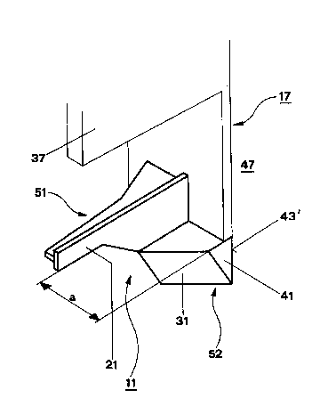
Fig. 9 shows a further embodiment variation of a proposed
buffer deflecting device 11. Shown here is the left-hand
portion of such a device, which is arranged on the left and
right hand sides of a prior art shock wave-damping and UIC-
compatible communication device 17. In this embodiment, the
impact face 41 of buffer deflecting device 11 aligns with slip
face 37, which forms the parting plane of communication device
17.
In addition, the vertically-running face 43' of buffer
deflecting device 11 closes off cross over gap 47 at virtually
the same level as the latter, so that the Berne Clearance is
maintained in the transverse direction of the rail vehicle.
Buffer deflecting device 11 features a first attachment 51
comprising a tongue-shaped withdrawal surface 21 and a second
attachment 52 comprising a backwardly-angled slip face 31 and
; 20 a triangular impact face 41.
i: :
Attachments 51 and 52, which are attached to the sides of
communication device 17, are so arranged that impact face 41
is oriented parallel to withdrawal surface 21 and is displaced
from the latter toward the front by a distance "a".
Should a host buffer 15, 15' be pressed backward by an
opposing buffer 16, 16' (Fig. 5, 6), projecting communication
device 17 is pulled back by means of the travel of host buffer
15, 15', because the rearward face of buffer head 35 of such
host buffer sits against an attachment 51 possessing a
withdrawal surface 21 (Fig. 9).
When two sets of buffers 15, 15' and 16, 16' (Figs 7 and 8),
- : - . ~ ,
,.
- .
: .. : -, : . : .
2~B7~
11
which slide laterally in relation to each other, are pressed
together, inner sloping buffer head face 26 of opposite buffer
16, 16' slides along slip face 31 of an attachment 52 (Fig. 9)
which is angled to the rear, and pushes communication device
17 backward by successive steps.
In the case of maximum lateral shifting between buffers 15,
15' and 16, 16', opposite buffer 16, 16' (Fig. 9) finally
slides up along the impact face 41 of attachment 52 of a
buffer deflecting device 11.
Such an arrangement prevents the opposite buffers 16, 16', at
any point of their lateral shift relative to buffers 15 and
15', from colliding with parts of a communication device 17.
A simple embodiment of buffer deflecting device 1 or 11
when arranged in mirror-reversed fashion on the left and right
hand sides of a communication device 17, need comprise merely
slip face 3 or 31 and impact face 4 or 41, so that only one
attachment 52 (Fig. 9) is required for a buffer deflecting
device 11.
:, :
All individual parts and individual distinguishing
characteristics set forth both in the disclosure and/or
;- figures, as well as theix permutations, combinations and
variations are novel. This applies most particularly to n
components and individual distinguishing characteristics whose
values are n=l to n greater than infinity.
, , :
,