Sélection de la langue

Search

Sommaire du brevet 2008952 

Énoncé de désistement de responsabilité concernant l'information provenant de tiers

Une partie des informations de ce site Web a été fournie par des sources externes. Le gouvernement du Canada n'assume aucune responsabilité concernant la précision, l'actualité ou la fiabilité des informations fournies par les sources externes. Les utilisateurs qui désirent employer cette information devraient consulter directement la source des informations. Le contenu fourni par les sources externes n'est pas assujetti aux exigences sur les langues officielles, la protection des renseignements personnels et l'accessibilité.

Disponibilité de l'Abrégé et des Revendications

L'apparition de différences dans le texte et l'image des Revendications et de l'Abrégé dépend du moment auquel le document est publié. Les textes des Revendications et de l'Abrégé sont affichés :

  • lorsque la demande peut être examinée par le public;
  • lorsque le brevet est émis (délivrance).
(12) Demande de brevet: (11) CA 2008952
(54) Titre français: DISPOSITIF DE SECURITE
(54) Titre anglais: SAFETY APPARATUS
Statut: Réputée abandonnée et au-delà du délai pour le rétablissement - en attente de la réponse à l’avis de communication rejetée
Données bibliographiques
(51) Classification internationale des brevets (CIB):
  • F23M 07/00 (2006.01)
  • F23M 11/00 (2006.01)
  • F26B 25/00 (2006.01)
  • F26B 25/12 (2006.01)
  • F27D 01/18 (2006.01)
  • F27D 21/00 (2006.01)
(72) Inventeurs :
  • HENGELMOLEN, ADRIANUS J. (Royaume-Uni)
  • HENGELMOLEN, ADRIANUS J. (Royaume-Uni)
(73) Titulaires :
  • ADRIANUS J. HENGELMOLEN
  • COPERMILL LIMITED
(71) Demandeurs :
  • ADRIANUS J. HENGELMOLEN (Royaume-Uni)
  • COPERMILL LIMITED (Royaume-Uni)
(74) Agent: SMART & BIGGAR LP
(74) Co-agent:
(45) Délivré:
(22) Date de dépôt: 1990-01-30
(41) Mise à la disponibilité du public: 1990-08-04
Licence disponible: S.O.
Cédé au domaine public: S.O.
(25) Langue des documents déposés: Anglais

Traité de coopération en matière de brevets (PCT): Non

(30) Données de priorité de la demande:
Numéro de la demande Pays / territoire Date
8902497.0 (Royaume-Uni) 1989-02-04

Abrégés

Abrégé anglais


IMPROVEMENTS IN OR RELATING TO SAFETY APPARATUS
Inventor: Adrianus Jacobus Hengelmolen
ABSTRACT
A safety door for a furnace or like apparatus is operable
to open under the force of a hydraulic cylinder when the pressure
under the furnace exceeds a predetermined upper limit corresponding
to an abnormally high pressure caused by an explosion within the
furnace or like apparatus. The safety door thereby prevents the
furnace from being permanently damaged by an explosion.

Revendications

Note : Les revendications sont présentées dans la langue officielle dans laquelle elles ont été soumises.


I CLAIM:
1. Safety apparatus for a furnace or like apparatus including
a door which is normally sealed closed against a portion of the
furnace wall and including hydraulic cylinder means operative in
response to a rapid build up of pressure within the furnace to
open the door.
2. Safety apparatus as claimed in claim 1 in which the door or
a mounting holding the door is pivotably mounted and two
hydraulic cylinders are attached to the opposite end of the
door, or mounting, to the pivot.
3. Safety apparatus as claimed in claim 2 in which the
hydraulic cylinders are double acting providing in normal
operation hydraulic force to maintain the door in a sealed
condition and providing hydraulic power to force open the door
when a sudden rise in pressure within the furnace is detected.
4. Safety apparatus as claimed in claim 3 in which a gas
actuated control member is connected to the furnace and to the
hydraulic supply line to the hydraulic cylinders which control
member is operative to detect a pressure within the furnace
above a safe operating pressure and to switch the hydraulic
supply to the hydraulic cylinders to cause the door to be opened
under hydraulic pressure.
5. Safety apparatus as claimed in claim 4 in which the
hydraulic cylinders are of the double acting type, the cylinders
being operatively connected to provide, when acting in a first
direction a closing force for the door and to provide when
acting in the second direction, a rapid opening of the door.

6. Safety apparatus as claimed in claim 5 in which the door is
provided with a seal the seal being operative to provide a gas
tight closure for the furnace, and in which the cylinders when
acting in the first position provide a closing pressure for the
seal.
7. Safety apparatus as claimed in claim 6 in which the door is
provided with roller means operative to allow the door to be
moved when the cylinders are released from operating in the
first position, to allow access to the furnace.

Description

Note : Les descriptions sont présentées dans la langue officielle dans laquelle elles ont été soumises.

20~89~
IMPROVEMENTS IN OR R~LATING TO SAFETY APPARATUS
The present invention relates to safety apparatus and more
particularly for relieving excessive pressure in a boiler,
furnace or similar system.
Boiler systems normally operate at a pressure which is
above atmospheric and they are designed to withstand such
pressure. Recent designs of furnaces, particularly those which
are effective in pollution control may also operate at pressure
and/or may have clamping control "valve" arrangements which can,
if they malfunction, cause a sudden build up of pressure within
the furnace.
Known safety devices comprise a weakened section of a
boiler which is .capable of withstanding normal pressures but
which will ~'blow~ open if the pressure rises to above a set
safety limit. In boilers this may comprise a weakened wall
section and in furnaces this may comprise a thinner thermal wall
forming a weakened "window".
There are a number of disadvantages with respect to this
known safety system among which are that the system is not able
to be tested since it i9 effectively destroyed by any test and
has to be rebuilt. Also, the system is found not to be very
effective in dealing with extremely rapid rises in pressure such
as an explosion within the boiler or furnace. Additionally once
~'blown" the safety device has to be carefully reconstructed and
this is normally only able to be done by skilled craftsmen.
It is an object of the present invention to provide safety
apparatus for a furnace or boiler or like system hereinafter
referred to as a furnace which is readily testable, and which is
easily reset and which is able to respond to extremely rapid
rises in interval pressure such as caused by an explosion.
According to the present invention there is provided safety
apparatus for a furnace including a door which is normally
sealed closed against a portion of the furnace wall and
including hydraulic cylinder means operative in response to a
rapid build up of pressure within the furnace to open the door.

2 2~89~2
Preferably the door or a mounting holding the door is
pivotably mounted and two hydraulic cylinders are attached to
the opposite end of the door, or mounting, to the pivot.
Preferably the hydraulic cylinders are double acting
thereby providing in normal operation hydxaulic force to
maintain the door in a sealed condition and providing hydraulic
power to force opep the door when a sudden rise in pressure
within the furnace is detected.
Preferably a gas actuated control member is connected to
the furnace and to the hydraulic supply line to the hydraulic
cylinder which control member is operative to detect a pressure
within the furnace above a safe operating pressure and to switch
the hydraulic supply to the hydraulic cylinder to cause the door
to be opened under hydraulic pressure.
Embodiments of the present invention will now be disclosed,
by way of example with reference to the accompanying drawings,
in which:-
Figure 1 schematically illustrates a furnace with safetyapparatus according to the present invention;
Figure 2 shows diagrammatically the safety apparatus of
Figure 1 in front elevation; and
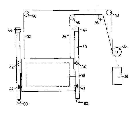
Figure 3 diagrammatically shows the safety apparatus of
Figure 2 in side elevation. `
With reference now to Figure 1 a furnace 10 is shown the
furnace being mounted on suitable pillars 12, 14. The design of
the furnace is immaterial to the invention and as stated
hereinbefore the safety apparatus can be used on boilers or
spray driers or any similar apparatus which is subject to the
possibility of internal explosions. Thus the furnace is only
exemplary but the invention is particularly applicable to
furnaces since these are often subject to explosions especially
if used to burn or melt scrap material.
The furnace 10 is provided with a door 16 which is normally
liftable by means 18 described in greater detail in Figure 2.

2~
The pressure within the furnace 10 is detected by a
detector 20 and a ~signal~ is fed via connection 22 to one or
more hydraulic actuating devices (cylinders) 24, 24~. ~he
connection 22 may be electronic if the furnace is electronically
controlled or may be hydraulic or gas pressure operated.
With reference to Figures 2 and 3 the door 16 is, in this
example, slidably mounted on a frame 30 and is liftable by means
of wire ropes 32, 34 which are attached to a winding drum 36
driven by motor 38 and passover guide pulleys 40. Door 16 is
therefore slidable on rollers 42 to enable feed material to be
put into furnace 10.
Frame 30 is pivotted at its upper end on pivots 44 which
are attached to suitable hinges on the main frame of the furnace
10. The door 16 when lowered into its closed position as shown
is sealed by seals 50, 52, which surround the door. An upper
roller 54 may also be provided which may act as a guide roller
for the door when being raised and lowered to prevent the door
from hitting the upper part of the seal 52.
At the bottom of frame 30 there are attached the operating
rods of two hydraulic cylinders 60, 62 which are anchored or
attached ~Figure 3) to part of the main frame of the furnace.
The cylinders 60, 62 are preferably of the double acting type
with two inlets 70, 72 on either side of piston 74. In known
manner hydraulic fluid pressure applied on inlet 72 will cause
the piston 74 to move to the left and on inlet 70 will cause the
piston 74 to move to the right respectively closing and opening
door 16.
Normally when the furnace is operative piston 74 is in the
position shown in Figure 3 and it is moved only when there is
excessive pressure inside furnace 10 or when it is required to
open door 16.
In the latter case by gradually shutting off the hydraulic
pressure on inlet 72 the door 16 will be allowed to release from
the seals 50, 52 and may then be lifted. Scrap metal or other
material to be melted or burnt may then be loaded into the
furnace and door 16 lowered again. Returning pressure to inlet
k;;,,~

2~395~
. 4
72 will then force the door 16 back against seals 50, 52 thereby
sealing the opening 10' in furnace 10. Inlet 70 can be used to
provide pressure to actually force open door 16 if required but
this may not be necessary.
If pressure inside furnace 10 rises rapidly then this is
transmitted to control 80 which reacts to any rapid rise in air
pressure to provide a large increase in hydraulic pressure on
inlet line 70 and thereby to force piston 74 to move rapidly to
open door 16.
~ he principal advantages of this apparatus are that it is
possible to test the apparatus by causing an explosion, by
igniting a charge within the furnace, without damaging the
furnace since the door 16 can be closed again by release of the
excessive hydraulic pressure on inlet 70. Also the use of the
hydraulic rams 60, 62 (62 not shown in Figure 3 but is operative
as cylinder 60) ensures a very rapid opening of door 16.
With respect to a furnace therefore the main door can be
used as a safety door. With spray driers and boilers a special
door suitably hinged may be required but this may be constructed
from already present inspection ports.

Dessin représentatif
Une figure unique qui représente un dessin illustrant l'invention.
États administratifs

2024-08-01 : Dans le cadre de la transition vers les Brevets de nouvelle génération (BNG), la base de données sur les brevets canadiens (BDBC) contient désormais un Historique d'événement plus détaillé, qui reproduit le Journal des événements de notre nouvelle solution interne.

Veuillez noter que les événements débutant par « Inactive : » se réfèrent à des événements qui ne sont plus utilisés dans notre nouvelle solution interne.

Pour une meilleure compréhension de l'état de la demande ou brevet qui figure sur cette page, la rubrique Mise en garde , et les descriptions de Brevet , Historique d'événement , Taxes périodiques et Historique des paiements devraient être consultées.

Historique d'événement

Description Date
Inactive : CIB de MCD 2006-03-11
Inactive : Demande ad hoc documentée 1997-01-30
Inactive : Abandon.-RE+surtaxe impayées-Corr envoyée 1997-01-30
Demande non rétablie avant l'échéance 1995-07-30
Le délai pour l'annulation est expiré 1995-07-30
Inactive : Demande ad hoc documentée 1995-01-30
Réputée abandonnée - omission de répondre à un avis sur les taxes pour le maintien en état 1995-01-30
Demande publiée (accessible au public) 1990-08-04

Historique d'abandonnement

Date d'abandonnement Raison Date de rétablissement
1995-01-30
Titulaires au dossier

Les titulaires actuels et antérieures au dossier sont affichés en ordre alphabétique.

Titulaires actuels au dossier
ADRIANUS J. HENGELMOLEN
COPERMILL LIMITED
Titulaires antérieures au dossier
S.O.
Les propriétaires antérieurs qui ne figurent pas dans la liste des « Propriétaires au dossier » apparaîtront dans d'autres documents au dossier.
Documents

Pour visionner les fichiers sélectionnés, entrer le code reCAPTCHA :


Pour visualiser une image, cliquer sur un lien dans la colonne description du document. Pour télécharger l'image (les images), cliquer l'une ou plusieurs cases à cocher dans la première colonne et ensuite cliquer sur le bouton "Télécharger sélection en format PDF (archive Zip)" ou le bouton "Télécharger sélection (en un fichier PDF fusionné)".

Liste des documents de brevet publiés et non publiés sur la BDBC .

Si vous avez des difficultés à accéder au contenu, veuillez communiquer avec le Centre de services à la clientèle au 1-866-997-1936, ou envoyer un courriel au Centre de service à la clientèle de l'OPIC.


Description du
Document 
Date
(aaaa-mm-jj) 
Nombre de pages   Taille de l'image (Ko) 
Dessins 1990-08-03 2 35
Revendications 1990-08-03 2 69
Abrégé 1990-08-03 1 20
Description 1990-08-03 4 204
Dessin représentatif 1999-07-27 1 8
Taxes 1994-05-11 1 57
Taxes 1993-04-25 1 48
Taxes 1992-01-23 1 39