Sélection de la langue

Search

Sommaire du brevet 2008982 

Énoncé de désistement de responsabilité concernant l'information provenant de tiers

Une partie des informations de ce site Web a été fournie par des sources externes. Le gouvernement du Canada n'assume aucune responsabilité concernant la précision, l'actualité ou la fiabilité des informations fournies par les sources externes. Les utilisateurs qui désirent employer cette information devraient consulter directement la source des informations. Le contenu fourni par les sources externes n'est pas assujetti aux exigences sur les langues officielles, la protection des renseignements personnels et l'accessibilité.

Disponibilité de l'Abrégé et des Revendications

L'apparition de différences dans le texte et l'image des Revendications et de l'Abrégé dépend du moment auquel le document est publié. Les textes des Revendications et de l'Abrégé sont affichés :

  • lorsque la demande peut être examinée par le public;
  • lorsque le brevet est émis (délivrance).
(12) Demande de brevet: (11) CA 2008982
(54) Titre français: METHODE, ELEMENT D'ANCRAGE ET DISPOSITIF TENDEUR POUR TIGE
(54) Titre anglais: METHOD, ANCHORING ELEMENT AND DEVICE FOR TENSIONING A ROD
Statut: Réputée abandonnée et au-delà du délai pour le rétablissement - en attente de la réponse à l’avis de communication rejetée
Données bibliographiques
(51) Classification internationale des brevets (CIB):
  • E02B 07/20 (2006.01)
  • E21D 21/00 (2006.01)
  • F16B 37/08 (2006.01)
(72) Inventeurs :
  • ISLER, ERWIN (Suisse)
(73) Titulaires :
  • H. WEIDMANN AG
(71) Demandeurs :
  • H. WEIDMANN AG (Suisse)
(74) Agent: BERESKIN & PARR LLP/S.E.N.C.R.L.,S.R.L.
(74) Co-agent:
(45) Délivré:
(22) Date de dépôt: 1990-01-31
(41) Mise à la disponibilité du public: 1990-08-06
Licence disponible: S.O.
Cédé au domaine public: S.O.
(25) Langue des documents déposés: Anglais

Traité de coopération en matière de brevets (PCT): Non

(30) Données de priorité de la demande:
Numéro de la demande Pays / territoire Date
401/89-9 (Suisse) 1989-02-06

Abrégés

Abrégé anglais


A B S T R A C T
A nut (15), for tensioning a rock-anchor-rod, has a
tubular body (25) with a saw-tooth thread (28). The body
(25) of the nut is divided, by a plurality of longitudinal
slots, into segments (31). The said segments are connected
together by cross-sectionally U-shaped resiliently flexible
ribs (26). One end-face of the nut (15) has a
convex-spherical flange (17) which bears against an
anchor-plate. The slots (30) extend through the flange (17)
as far as the inner wall of the ribs (26). Between the ribs
(26), the flange (17) carries radial incisions (37) extending
as far as the body (25) of the nut. As a result of this the
segments (31) are tangentially resilient. In order to
tension the anchor-rod, the nut (15) is pushed axially onto
the saw-tooth thread of the rod. The jaws of a tensioning
device engage in the thread at the free end of the rod and
bear against the nut (15). When the said cheeks apply
tension to the anchor-rod, the nut (15) is pressed to the
anchor-plate. This ensures rapid and accurate preloading of
the anchor-rod. (Fig. 3).

Revendications

Note : Les revendications sont présentées dans la langue officielle dans laquelle elles ont été soumises.


THE EMBODIMENTS OF THE INVENTION IN WHICH AN EXCLUSIVE
PROPERTY OR PRIVILEGE IS CLAIMED ARE DEFINED AS FOLLOWS:
1. A method for tensioning a rod (2) comprising a
plurality of equally spaced, saw-tooth grooves (8) arranged
in a row adjacent the free end of section (5) of the rod, a
tension-element (56) being brought into engagement with the
grooves (8) of section (5) of the rod, the rod (2) being
tensioned with the tension-element (56) by means of a
tensioning-device (1), and an anchoring-element (15),
engaging in the grooves (8) in section (5) of the rod, being
brought to bear against a support (19), thereupon the
tensioning-device (1) is released and the tension-element
(56) is removed, characterized in that when the rod (2) is
tensioned, the tensioning-device (1) bears against the
anchoring-element (15) and, simultaneously with the
tensioning of the rod (2), the anchoring-element (15) is
pressed to the support (19).
2. An anchoring-element for the implementation of the
method according to claim 1, comprising a tubular body (25)
with saw-tooth grooves (29) in an axial passage (27) engaging
with saw-tooth grooves (8) in a rod (2) and having radially
projecting ribs (26) extending axially and integral with
tubular body (25), characterized in that the said tubular
body is divided into segments (31) by axial slots (30); and
in that the ribs (26) are cross-sectionally U-shaped, are
resiliently flexible and connect the segments (31) together,

-2-
so that the said segments are connected to the said ribs
tangentially flexibly but radially inflexibly.
3. An anchoring-element according to claim 2,
characterized in that an end-flange (17) is formed onto one
axial end of each rib; in that the slots (30) extend through
the said end-flange, projecting thereinto almost as far as
the inner wall of the ribs (26); and in that radial incisions
(37) are formed in the end-flange (17), from the outside,
between the ribs (26), the said incisions projecting into the
area of the body.
4. An anchoring-element according to claim 3,
characterized in that the end-flange (17) extends radially
over the outside diameter of the ribs (26); in that the said
flange has a convex-spherical outer surface (16) and a
concave-spherical inner surface (35); and in that the part of
the end-flange (17) outside of the ribs (26) is supported
upon the said ribs by webs (34).
5. An anchoring-element according to one of claims 2
to 4, characterized in that the grooves (29) of the body (25)
are spiral and form a nut-thread (28).
6. An anchoring-element according to claim 5,
characterized in that it comprises twelve slots (30) and
twelve ribs (26); and in that all of the ribs (26) comprise,

-3-
radially outwardly, a roof-shaped section (33) as seen
cross-sectionally, the said sections (33) together forming a
double-hexagon (39) for engagement with a double-hexagon
wrench.
7. An anchoring-element according to one of claims 2
to 6, characterized in that it is made of a fibre-reinforced
synthetic material.
8. A tensioning device for the implementation of the
method according to claim 1, comprising a housing (44) upon
which a tension-element (56), having saw-tooth grooves (57)
for engagement with saw-tooth grooves (8), at an end-section
(5) adjacent the free end of a rod (2), is axially
displaceable; comprising a supporting-element (47) secured to
the housing (44) and an actuating member (46) for shifting
the tension-element (56) axially in relation to the
supporting-element (47), characterized in that the
supporting-element (47) comprises a coaxial opening (48)
through which the rod (2) passes and, for support against an
anchoring-element (15) placed upon the rod (2), it is
provided with saw-tooth grooves (29) for engagement with the
grooves (8) in the rod (2).
9. A device according to claim 8, characterized in
that the tension-element comprises a plurality of jaws (56)
which are adapted to be shifted from a basic position in

-4-
which the grooves (57) may be brought into engagement with
the grooves (8) in the rod (2), to a radially disengaged
position by at least the radial depth of the said grooves
(57).
10. A device according to claim 3 or 9, characterized
in that the supporting-element is a convexly cambered
end-surface (47) of the housing (44) bearing upon a concavely
spherical inner surface (35) of an end-flange (17) of the
anchoring-element (15).

Description

Note : Les descriptions sont présentées dans la langue officielle dans laquelle elles ont été soumises.

20085~8.~2
S P E C I F I C A T I O N
For the purpose of stabilizing rock, e.g. in
tunnelling or mining, tension-rods are used with a rod
anchored in the rock and having a nut screwed to its free
end. The said nut bears against an anchor-plate which bears
against the rock. In the case of steel tension-rods, the nut
is usually tightened with a torque-wrench. This method of
tensioning is, however, highly inaccurate since the torque
applied with the wrench fluctuates considerably and settling
of the anchor-plate may lead to uncontrolled reduction of
rod-tension.
This method of tensioning has also been
unsatisfactory in the case of rods made of fibre-reinforced
synthetic materials since such materials have low torsional
strength.
15A method according to the preamble to claim 1 is
known to have been used previously. This is a method for
tensioning rods made of fibre-reinforced synthetic materials.
A known tension-rod for this purpose is described in US
~`Patent 4,523,880. The free end of the rod carries a
saw-tooth thread onto which a nut is screwed. The nut bears
against an anchor-plate. Tensioning is effected by means of
a device using an auxiliary nut which is screwed to the free
end of the rod outside the main nut. The auxiliary nut is
axially displaceable, in the frame of the device, by means of
a hydraulic cylinder. The frame comprises a tripod which

Z00~98~
--2--
bears against the rock outside the anchor-plate. When the
cylinder is actuated, the auxiliary nut preloads the
anchor-rod, after which the main nut can be screwed manually
up to the anchor-plate. This method and this device are
quite complicated.
It is the purpose of the present invention to
develop the above-mentioned method, anchoring-element and
tensioning-device so that the rod may be tensioned rapidly.
This purpose is accomplished by the characteristics set forth
in claims 1, 2 and 8.
An example of embodiment of the invention is
explained hereinafter in connection with the drawings
attached hereto, wherein:
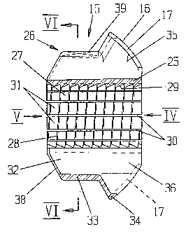
Fig. 1 is an axial section through a tensioning-device;
Fig. 2 is an axial section along the line II-II in Fig.l;
Fig. 3 is an axial section through a nut along the line
III-III in Fig.4;
Figs. 4 and 5 are end-elevations of the nut according to
Fig. 3 in the direction of arrows 4 and 5 in Fig.3,
and
Fig. 6 is a cross-section along the line VI-VI in Fig.3.
The tensioning-device 1 shown in Figs. 1 and 2 is
used to tension a fibre-reinforced synthetic anchor-rod 2.
The said rod is shown in a drill-hole 3 in rock 4, only a
section 5, adjacent to free end thereof, being visible. The
anchoring end may be designed according to US Patent
'' ', ', ':
.

~008982
4,523,880, for example. Cast onto end-section 5 is a sleeve
6 made of a fibre-reinforced synthetic material, the exterior
of which carries a saw-tooth thread 7. The saw-tooth grooves
8 of thread 7 have flat sides 9 facing towards the free end
of the rod and steep sides 10 facing away from the end of the
rod.
Fitted to thread 7 is a nut 15 acting as an
anchoring element. This bears with the convex-spherical
outer surface 16 of an end-flange 17 against the
concave-spherical surface 18 of an anchor-plate 19.
Anchor-plate 19 bears against rock 4 with ribs 20 designed to
crumple.
Nut 15 is shown in greater detail in Figs. 3 to 6.
It is injection-moulded out of a fibre-reiforced synthetic
material and consists of a tubular body 25 with moulded ribs
26 and an end-flange 17. Formed in axial passage 27 in body
25 is a saw-tooth nut-thread 28 with saw-tooth grooves 29
which match grooves 8. Body ?5 is divided by twelve
longitudinal slots 30 into twelve segments 31. Ribs 26 are
cross-sectionally U-shaped with radially directed U-legs 32
and a somewhat roof-shaped connecting section 33. Ribs 26
are resiliently flexible. They join segments 31 together so
that while the said ribs can spring tangentially in relation
to each other, they are radially rigid in relation to ribs
26. Towards flange 17, sections 33 merge into
semi-cylindrical webs 34 arranged at an angle to the axis of
tubular body 25. The, said webs support the outer areas of

2~0~98~
--4--
flange 17, projecting beyond the outside diameter of ribs 26,
against the latter. Sections 33 form a double hexagon 39,
allowing nut 15 to be tightened or slackened with a wrench.
Facing spherical outer surface 16, end-flange 17 has a
concave-spherical inner surface 35. The space enclosed by
legs 32, section 33 and web 34 extends, as an opening,
through flange 17 so that, in the said flange, slots 30
extend as far as the inner wall of webs 34. Between ribs 26,
end-flange 17 has radial incisions 37 extending as far as
tubular body 25. As a result of this design, the resilient
flexibility of ribs 26 and webs 34 is not impaired by flange
17. At the opposite end, the space enclosed by ribs 26 is
closed off by elements 38. In these elements slots 30 again
extend radially as far as the inner wall of sections 33.
According to Fig 1 tensioning device 1 has a
housing 44. At the rear axial end, housing 44 is screwed to
piston-rod 45 of a single-acting hydraulic-cylinder unit 46.
Housing 44 has a concavely cambered end-surface 47 which
bears against concave-spherical inner surface 35 of flange
17, and an axial opening 48 surrounding ribs 26. End-surface
47 acts as a support for tensioning device 1 on nut 15.
Screwed to the front end of cylinder 50 of hydraulic unit 46
is a ring 51 carrying four axially parallel rods 52. Screwed
to the front end of each rod 52 is a carrier 53 with a
passage 54 through which sleeve 6 passes. The front end of
carrier 53 has four radial T-shaped grooves 55 in which four
jaws 56 are adapted to move radially. These jaws have

2~)0~982
saw-tooth nut-thread grooves engaging in grooves 8 in rod 2.
Arranged on the back of carrier 53 is a coaxial actuating
ring 58 which is axially displaceable on rods 52 and is
preloaded in relation to carrier 53 by means of compression
rings 59. A sleeve 60 is displaceable upon each of two rods
52a, the said sleeves being rigidly connected to ring 58 and
projecting rearwardly through a passage 61 in housing 44.
Secured to the rear end of each sleeve 60 is an actuating
grip 62 adjacent a handle formed on ring 51. Secured to
actuating ring 58 are four pins 64 running at an angle to the
axis of housing 44. Pins 64 pass through passages 65 in jaws
56. In Fig. 1 they are shown at an angle of 45.
The device illustrated operates as follows: after
anchor-rod 2 has been placed in drill-hole 3, anchor-plate 19
is placed against rock 4 and nut 15 is pushed onto sleeve 6
until it bears against anchor-plate 19. Because of
tangentially resilient segments 31, nut 15 need merely be
moved axially which is much faster than screwing.
Tensioning-device 1 is now held by grip 63 and actuating grip
62 is simultaneously drawn back. This causes ring 58 to move
away from carrier 53 against the force of springs 59, while
pins 64 move jaws 56 radially outwardly. This makes it
possible to bring device 1 over sleeve 6 until it bears
against end-surface 47. When actuating grip 62 is released,
springs 59 urge ring 58 forwardly and pins 64 move jaws 56
radially inwardly so that jaw-grooves 57 engage with
rod-grooves 8. Pressurized oil is now fed to hydraulic unit

6 2UC~89~32
46. Piston-rod 45 pushes housing 44 and thus end-surface 47
forwardly and cylinder 50 pulls jaws 56 rear-wardly by means
of rods 52 and carrier 53. This tensions rod 2. At the same
time nut 15 is pressed to anchor-plate 19 by the
counter-force and again thread-grooves 8 are jumped over by
the tangential springing of segments 31. Cambered end-surface
47 assists in expanding nut 15. Since the full preload force
of rod 2, during preloading, also presses nut 15 to
anchor-plate 19, ribs 20 of the latter bear firmly against
rock 4 so that, when hydraulic unit 46 is released, accurate
rod-preloading, exactly meterable, is obtained by hydraulic
pressure. As soon as hydraulic unit 46 has been released, a
pull on actuating grip 62 opens jaws 56 and tensioning device
1 is removed axially from the free end of the rod. The
lS radial components of the supporting force on end-flange 17,
which are transferred directly to segments 31 by radially
rigid ribs 26, compress segments 31 radially, thus keeping
nut-thread 28 firmly in engagement with the thread on the
rod. In addition to this, this radial compression greatly
improves the transfer of force from sleeve 6 to anchor-rod 2.
The described tensioning device 1 and nut lS make
it possible to tension anchor-rod extremely quickly and
accuracy and reproducibility of the preload are considerably
improved as compared with previously known devices. This
allows optimal use to be made of the strength of anchor-rod
2.
The anchoring-element (nut lS) and the tensioning
;: .

200898Z
method described are also suitable in principle if
rod-grooves 8, anchoring-element grooves 29, and jaw-grooves
57 are annular and thus do not form threads. In this case,
rod cross-sections other than circular may be considered.

Dessin représentatif
Une figure unique qui représente un dessin illustrant l'invention.
États administratifs

2024-08-01 : Dans le cadre de la transition vers les Brevets de nouvelle génération (BNG), la base de données sur les brevets canadiens (BDBC) contient désormais un Historique d'événement plus détaillé, qui reproduit le Journal des événements de notre nouvelle solution interne.

Veuillez noter que les événements débutant par « Inactive : » se réfèrent à des événements qui ne sont plus utilisés dans notre nouvelle solution interne.

Pour une meilleure compréhension de l'état de la demande ou brevet qui figure sur cette page, la rubrique Mise en garde , et les descriptions de Brevet , Historique d'événement , Taxes périodiques et Historique des paiements devraient être consultées.

Historique d'événement

Description Date
Inactive : CIB de MCD 2006-03-11
Inactive : Demande ad hoc documentée 1997-01-31
Inactive : Abandon.-RE+surtaxe impayées-Corr envoyée 1997-01-31
Demande non rétablie avant l'échéance 1994-07-31
Le délai pour l'annulation est expiré 1994-07-31
Inactive : Demande ad hoc documentée 1994-01-31
Réputée abandonnée - omission de répondre à un avis sur les taxes pour le maintien en état 1994-01-31
Demande publiée (accessible au public) 1990-08-06

Historique d'abandonnement

Date d'abandonnement Raison Date de rétablissement
1994-01-31
Titulaires au dossier

Les titulaires actuels et antérieures au dossier sont affichés en ordre alphabétique.

Titulaires actuels au dossier
H. WEIDMANN AG
Titulaires antérieures au dossier
ERWIN ISLER
Les propriétaires antérieurs qui ne figurent pas dans la liste des « Propriétaires au dossier » apparaîtront dans d'autres documents au dossier.
Documents

Pour visionner les fichiers sélectionnés, entrer le code reCAPTCHA :


Pour visualiser une image, cliquer sur un lien dans la colonne description du document (Temporairement non-disponible). Pour télécharger l'image (les images), cliquer l'une ou plusieurs cases à cocher dans la première colonne et ensuite cliquer sur le bouton "Télécharger sélection en format PDF (archive Zip)" ou le bouton "Télécharger sélection (en un fichier PDF fusionné)".

Liste des documents de brevet publiés et non publiés sur la BDBC .

Si vous avez des difficultés à accéder au contenu, veuillez communiquer avec le Centre de services à la clientèle au 1-866-997-1936, ou envoyer un courriel au Centre de service à la clientèle de l'OPIC.

({010=Tous les documents, 020=Au moment du dépôt, 030=Au moment de la mise à la disponibilité du public, 040=À la délivrance, 050=Examen, 060=Correspondance reçue, 070=Divers, 080=Correspondance envoyée, 090=Paiement})


Description du
Document 
Date
(aaaa-mm-jj) 
Nombre de pages   Taille de l'image (Ko) 
Revendications 1990-08-05 4 87
Abrégé 1990-08-05 1 21
Dessins 1990-08-05 4 138
Description 1990-08-05 7 180
Dessin représentatif 1999-07-28 1 12
Taxes 1993-01-26 1 26
Taxes 1991-12-12 1 20