Sélection de la langue

Search

Sommaire du brevet 2009302 

Énoncé de désistement de responsabilité concernant l'information provenant de tiers

Une partie des informations de ce site Web a été fournie par des sources externes. Le gouvernement du Canada n'assume aucune responsabilité concernant la précision, l'actualité ou la fiabilité des informations fournies par les sources externes. Les utilisateurs qui désirent employer cette information devraient consulter directement la source des informations. Le contenu fourni par les sources externes n'est pas assujetti aux exigences sur les langues officielles, la protection des renseignements personnels et l'accessibilité.

Disponibilité de l'Abrégé et des Revendications

L'apparition de différences dans le texte et l'image des Revendications et de l'Abrégé dépend du moment auquel le document est publié. Les textes des Revendications et de l'Abrégé sont affichés :

  • lorsque la demande peut être examinée par le public;
  • lorsque le brevet est émis (délivrance).
(12) Brevet: (11) CA 2009302
(54) Titre français: SYSTEME DE MODULATION DE LA COULEUR ET DE L'INTENSITE DE LA LUMIERE
(54) Titre anglais: LIGHT COLOR AND INTENSITY MODULATION SYSTEM
Statut: Durée expirée - au-delà du délai suivant l'octroi
Données bibliographiques
Abrégés

Abrégé anglais


There is disclosed a light color and intensity
modulation system having an output to be connected to a
color light projector and an input to receive a hue control
signal and an intensity control signal including at least
one modulation frequency component F. The system comprises
a color scaling device, receiving in use the hue signal,
the color scaling device producing a plurality of color
component signals, the plurality of color component signals
being supplied as the output to the color light projector,
and an intensity control device, receiving in use the
intensity control signal, the intensity control device
comprising a low frequency oscillator whose output is an
intensity modulation signal for varying an intensity of the
plurality of color component signals between a preset
minimum and a preset maximum value, the oscillator having a
frequency responsive to the at least one modulation
frequency component F of the intensity control signal, the
plurality of color component signals to control in use the
projector. The projected light can have a relaxing visual
effect.

Revendications

Note : Les revendications sont présentées dans la langue officielle dans laquelle elles ont été soumises.


The embodiments of the invention in which an
exclusive property or privilege is claimed are defined as
follows:
1. A light color and intensity modulation
system having an output to be connected to a color light
projector and an input to receive a hue control signal and
an intensity control signal including at least one
modulation frequency component F, said system comprising:
color scaling means, receiving in use said hue
signal, said color scaling means producing a plurality of
color component signals, said plurality of color component
signals being supplied as said output to said color light
projector; and
intensity control means, receiving in use said
intensity control signal, said intensity control means
comprising a low frequency oscillator whose output is an
intensity modulation signal for varying an intensity of
said plurality of color component signals between a preset
minimum and a preset maximum value, said oscillator having
a frequency responsive to said at least one modulation
frequency component F of said intensity control signal,
said plurality of color component signals to control in use
said projector.
2. A light color and intensity modulation
system as claimed in claim 1, wherein said plurality of
color component signals comprises three said signals, so
that in use three primary colors used by said projector may
be modulated to obtain any color of the visible spectrum.
3. A light color and intensity modulation
system as claimed in claim 1, wherein said intensity
control signal includes, in addition to said component F

being a first component, a second component, said second
component controlling a scaling factor of said output of
said low frequency oscillator, said modulation signal being
determined by a difference given by a maximum product of
said output of said low frequency oscillator and said
scaling factor less an instantaneous product of said output
of said low frequency oscillator and said scaling factor.
4. A light color and intensity modulation
system as claimed in claim 3, wherein said intensity
control signal further includes a third component, said
third component controlling an intensity factor of said
intensity modulation signal, such that said intensity
modulation signal is the product of said intensity factor
and said difference.
5. A light color and intensity modulation
system as claimed in claim 1, further comprising power
linearization means to scale an unscaled amplitude of said
plurality of color component signals to produce a scaled
amplitude, so that a relation between the unscaled
amplitude and an intensity of corresponding colors
projected by said color light projector is linear.
6. A light color and intensity modulation
system as claimed in claim 2, further comprising power
linearization means to scale an unscaled amplitude of said
three color component signals to produce a scaled
amplitude, so that a relation between the unscaled
amplitude and an intensity of corresponding colors
projected by said color light projector is linear.
7. A light color and intensity modulation
system as claimed in claim 1, further comprising power

dimmer means receiving said plurality of color component
signals to produce a variable power color projector lamp
output signal as said output signal.
8. A light color and intensity modulation
system as claimed in claim 5, further comprising power
dimmer means receiving said plurality of color component
signals to produce a variable power, color projector lamp
signal as said output signal.
9. A light color and intensity modulation
system as claimed in claim 2, further comprising video
signal generating means to convert said three color
component signals into an RGB video image signal.
10. A light color and intensity modulation
system as claimed in claim 6, further comprising video
signal generating means to convert said three color
component signals into an RGB video image signal.
11. A light color and intensity modulation
system as claimed in claim 2, further comprising television
RF modulator means to convert said three color component
signals into a color television image signal.
12. A light color and intensity modulation
system as claimed in claim 6, further comprising television
RF modulator means to convert said three color component
signals into a color television image signal.

Description

Note : Les descriptions sont présentées dans la langue officielle dans laquelle elles ont été soumises.

2~09~
The present invention relates to a light color
and intensity modulation system for use with a color light
projector.
It is well known that when exposed to a light or
sound pulsation with a frequency falling in the range of
human brainwave (about 2Hz to 20Hz), a subject will have a
tendency to himself generate brainwaves of the same
frequency through an effect known as entrainment or photic
driving. A further discussion of this effect can be found
in the book, "Megabrain", by M. Hutchison (pages 224-227,
1976, ISBN 0-345-34175-9). Specific brainwave frequencies
being associated with different mind states, the subject
may indirectly be led towards these mind states through
this brainwave induction. A light projection system can be
used to generate light color an intensity pulsations in the
brainwave frequency range (2Hz to 20Hz).
There currently exists light pulsation devices
for the purpose of entrainment or photic driving, which
usually use small lights within goggles applied close to
the eyes. Of course, the goggles obstruct the vision of
the subject and can be uncomfortable.
It is an object of the present invention to
provide a light color and intensity modulation system which
can project the light pulsation over the whole environment
surrounding the -subject. It is another object of the
invention to provide a system of the above-mentioned type,
wherein the light color is pulsated to produce new
induction effects.
According to the present invention there is
provided a light color an intensity modulation system
having an output to be connected to a color light projector
and an input to receive a hue (color) control signal and an
intensity control signal including at least one modulation

2~ 3~
frequency component F. The system comprises color scaling
means receiving in use the hue signal. The color scaling
means produce a plurality of color component signals that
are supplied as the output to the color light projector.
The system comprises intensity control means receiving in
use the intensity control signal. The intensity control
means comprise a low frequency oscillator whose output is
an intensity modulation signal for varying an intensity of
the plurality of color component signals between a preset
minimum and a preset maximum value, the oscillator having a
frequency responsive to the at least one modulation
frequency component F of the intensity control signal, the
plurality of color component signals to control in use the
projector.
According to the invention, the plurality of
color component signals preferably comprises three signals,
so that in use three primary colors used by the projector
may be modulated to obtain any color of the visible
spectrum.
Other objects and features of the present
invention will become clear by way of the following
detailed description of a preferred embodiment taken in
conjunction with the drawings wherein:
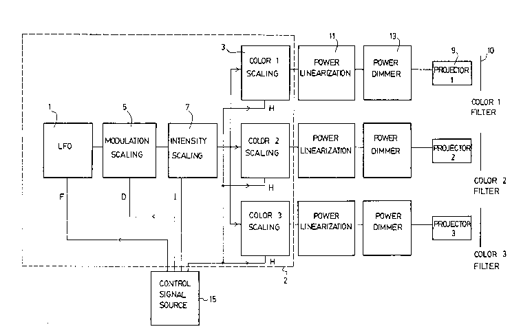
Figure 1 is a schematic block diagram of a light
color and intensity modulation system according to the
preferred embodiment;
Figure 2 shows a schematic block diagram of the
light color and intensity modulation system of Figure 1
connected to an RGB screen projection television unit.
As shown in Figure 1 the light color and
intensity modulation system 2 receives an input from
control signal source 15 and has three outputs connected to
power linearization circuits 11. The control signal source
15 provides a modulation frequency component signal F, a

20~3~
modulation depth component signal D and intensity component
signal I, and a hue signal H.
As is well known in the art, the hue signal
represents the color to be output and the color scaling
circuits 3 are provided for each color component to produce
each a color component signal. The modulation frequency
component F is fed to the low frequency oscillator 1. Low
frequency oscillator 1 generates a low frequency
oscillating waveform f (such as a sine wave) with a
frequency in the range of 0.01 to 20Hz and an amplitude
which ranges from 0 to 1 on a unit scale. In the preferred
embodiment, all control signals are digital.
The modulation depth component signal D is the
second component of the intensity control signal and is fed
to modulation scaling device 5. The modulation scaling
device 5 scales the amplitude of the waveform generated by
the low frequency oscillator in order to provide -a
modulating signal of adjustable depth D, such that the
output signal of modulation scaling device 5 is the
difference between 1 and the product of component D and the
output of oscillator 1, f. The output of the modulation
scaling device 5 is therefore between 0 and unity.
The final intensity processing step according to
the preferred embodiment is provided by intensity scaling
device 7 which receives intensity factor component I of the
intensity control signal. The output of device 7 is the
product of intensity factor component I and the output of
device 5. Of course the maximum output of device 7 is
determined by the magnitude of intensity factor component
I, which in the preferred embodiment is set to 1.
In summary, the intensity control means
including devices 1, 5, 7 operate as follows:

2009302
-
Input Range Control Function Output range
F~ Co.001, 20~ f(2~ *F*t) [ 0, 1 ~
D~ ro, 1 1 l-D*f r o~ l ~
I~ ~0, 1 ~ I*(1-D*f) ~ 0, I ~
The output of the intensity scaling device 7 is
fed as input to each color scaling device 3.
The details of the circuits of the low frequency
oscillators, modulation scaling device 5 and intensity
scaling device 7 are all well known in the art and
therefore no detailed description of them is given herein.
The circuit elements enclosed within the dotted
line box 2 comprise the light color and intensity
modulation system according to the preferred embodiment.
Power linearization devices 11 each receive
input from color scaling devices 3 and produce an output
signal which has been scaled by a linearizing function that
takes into account the perceived brightness to dissipated
power curve of the light projectors used. The scaling
function of the power linearization devices 11 depends on
the particular luminance to dissipated power curve of the
light bulbs used in the projectors 9, and the luminance to
subjective perceived brightness curve for a typical human
subject (as already known in the lighting industry).
The power dimmers 13 represent a standards
electronic circuit well known in the art which delivers the
required power to each projector 9. When the power dimmer
devices 13 are used with common AC power source, the
devices 13 will typically comprise a Triac chopping the AC
source wave at a variable phase during each cycle, with the
controlling device determining the proper phase for the

2~93 Df~
-
required power output.
Each of the projectors 9 and filters 10 are used
to produce by combination a color of the visible spectrum.
In the preferred embodiment, all projectors 9 shine light
through the filters 10 to strike the same surface area.
This surface area may be a projection screen or even a
blank wall.
As shown in Figure 2 the output of the color
scaling devices 3 are connected to a video signal generator
17 having an output connected to a video projector 19.
Video projector 19 is used to project a solid full screen
image on screen 21 whose color and intensity is varied by
the system 2. The output of video signal generator 17 may
be an RF modulated video signal or an RGB monitor signal.
In the preferred embodiment disclosed
hereinabove, the control signal source is a source of
digital data which can be any source of prerecorded digital
data (e.g. computer, MIDI sequencer, or audio-encoded
digital data track on an audio recording device). As the
invention may be used in conjunction with an audio system
to provide a multi-sensory automatic relaxation system, the
audio soundtrack and digital data track can be for example
recorded on a common multi-track audio recorder (DAT,
Cassette or Hi-Fi VCR). The control signal source may also
comprise an analogue data reader device coupled to an
analog to digital converter (ADC) alone or in addition to a
digital data source, and can also be able to switch between
analog and digital.
Thus, by way of example by using a MIDI Port as
a digital Port and assigning MIDI Note codes to the H, I, F
and/or D signals according to specific algorithms, a direct
translation of musical notes to color projection is
possible.
By assigning very slow waveforms (with periods

20~9302
of several seconds to several minutes) or slowly varying
random values to the H, I, F and/or D signals, a
perpetually varying light projection may also be obtained.
A number of such projector triads can be set up around a
room to create a soft ambient light effect.
The system according to the invention as
described hereinabove can be used to generate light
intensity pulsations in the brainwave frequency range (F~
~ 2Hz, 20Hz]), as well as color pulsations through the H
signal. By contrast with light pulsation devices that
already exist for this purpose, this system can project the
light pulsation over the whole environment surrounding the
subject. Modulating the color of the pulsation may also
lead to new induction effects.
The system according to the invention can
further be coupled with a complete multi-sensory system,
including sound and other parameters such as odors, video
projection, laser projection, and vibrations transmitted to
the body through sound resonators. Such a system can be
installed in a special-purpose light-proof, sound-proof
room, to be used an automatic relaxation system, or for
other specific therapeutic purposes. The system can be
computer-controlled, with the programmable elements (light
projection, sound spatialization, etc) driven by some
source of prerecorded digital data (e.g. computer, MIDI
sequencer, or audio-encoded digital data track on an audio
- recording device). The audio soundtracks and digital data
track can for example be recorded on a common multi-track
audio recorder (DAT, Tape, Cassette or Hi-Fi VCR).
It is to be understood that the above
description of the preferred embodiment of the invention is
not intended to limit the scope of the present invention as
defined in the appended claims.

Dessin représentatif
Une figure unique qui représente un dessin illustrant l'invention.
États administratifs

2024-08-01 : Dans le cadre de la transition vers les Brevets de nouvelle génération (BNG), la base de données sur les brevets canadiens (BDBC) contient désormais un Historique d'événement plus détaillé, qui reproduit le Journal des événements de notre nouvelle solution interne.

Veuillez noter que les événements débutant par « Inactive : » se réfèrent à des événements qui ne sont plus utilisés dans notre nouvelle solution interne.

Pour une meilleure compréhension de l'état de la demande ou brevet qui figure sur cette page, la rubrique Mise en garde , et les descriptions de Brevet , Historique d'événement , Taxes périodiques et Historique des paiements devraient être consultées.

Historique d'événement

Description Date
Inactive : Correspondance - TME 2010-08-10
Inactive : Périmé (brevet - nouvelle loi) 2010-02-05
Exigences pour le changement d'adresse - jugé conforme 2008-02-08
Déclaration du statut de petite entité jugée conforme 2008-01-21
Requête visant une déclaration du statut de petite entité reçue 2008-01-21
Demande visant la révocation de la nomination d'un agent 2008-01-21
Inactive : CIB de MCD 2006-03-11
Exigences pour le changement d'adresse - jugé conforme 1999-12-10
Inactive : Lettre officielle 1999-12-10
Inactive : Lettre officielle 1998-05-14
Inactive : Inventeur supprimé 1998-05-14
Inactive : TME en retard traitée 1998-05-01
Lettre envoyée 1998-02-05
Accordé par délivrance 1994-09-13
Demande publiée (accessible au public) 1991-08-05
Toutes les exigences pour l'examen - jugée conforme 1990-06-26
Exigences pour une requête d'examen - jugée conforme 1990-06-26

Historique d'abandonnement

Il n'y a pas d'historique d'abandonnement

Historique des taxes

Type de taxes Anniversaire Échéance Date payée
Annulation de la péremption réputée 1998-02-05 1998-05-01
TM (brevet, 8e anniv.) - petite 1998-02-05 1998-05-01
TM (brevet, 9e anniv.) - petite 1999-02-05 1998-12-10
TM (brevet, 10e anniv.) - petite 2000-02-07 1999-11-26
TM (brevet, 11e anniv.) - petite 2001-02-05 2000-12-22
TM (brevet, 12e anniv.) - petite 2002-02-05 2001-12-31
TM (brevet, 13e anniv.) - petite 2003-02-05 2003-01-06
TM (brevet, 14e anniv.) - petite 2004-02-05 2003-12-11
TM (brevet, 15e anniv.) - petite 2005-02-07 2005-02-02
TM (brevet, 16e anniv.) - petite 2006-02-06 2006-01-09
TM (brevet, 17e anniv.) - petite 2007-02-05 2006-12-20
TM (brevet, 18e anniv.) - petite 2008-02-05 2008-01-21
TM (brevet, 19e anniv.) - petite 2009-02-05 2009-01-13
Titulaires au dossier

Les titulaires actuels et antérieures au dossier sont affichés en ordre alphabétique.

Titulaires actuels au dossier
ALAIN MARTEL
Titulaires antérieures au dossier
S.O.
Les propriétaires antérieurs qui ne figurent pas dans la liste des « Propriétaires au dossier » apparaîtront dans d'autres documents au dossier.
Documents

Pour visionner les fichiers sélectionnés, entrer le code reCAPTCHA :


Pour visualiser une image, cliquer sur un lien dans la colonne description du document. Pour télécharger l'image (les images), cliquer l'une ou plusieurs cases à cocher dans la première colonne et ensuite cliquer sur le bouton "Télécharger sélection en format PDF (archive Zip)" ou le bouton "Télécharger sélection (en un fichier PDF fusionné)".

Liste des documents de brevet publiés et non publiés sur la BDBC .

Si vous avez des difficultés à accéder au contenu, veuillez communiquer avec le Centre de services à la clientèle au 1-866-997-1936, ou envoyer un courriel au Centre de service à la clientèle de l'OPIC.


Description du
Document 
Date
(aaaa-mm-jj) 
Nombre de pages   Taille de l'image (Ko) 
Page couverture 1994-02-28 1 12
Abrégé 1994-02-28 1 28
Revendications 1994-02-28 3 100
Description 1994-02-28 6 228
Dessins 1994-02-28 2 41
Dessins 1993-10-15 2 41
Abrégé 1993-10-15 1 28
Description 1993-10-15 6 228
Revendications 1993-10-15 3 100
Page couverture 1993-10-15 1 12
Description 1994-09-13 6 255
Page couverture 1996-02-02 1 15
Abrégé 1994-09-13 1 29
Revendications 1994-09-13 3 111
Dessins 1994-09-13 2 38
Dessin représentatif 1999-07-15 1 17
Avis concernant la taxe de maintien 1998-03-05 1 179
Quittance d'un paiement en retard 1998-05-14 1 170
Avis de rappel: Taxes de maintien 1998-11-09 1 118
Avis de rappel: Taxes de maintien 1999-11-08 1 119
Avis de rappel: Taxes de maintien 2000-11-07 1 121
Avis de rappel: Taxes de maintien 2001-11-06 1 121
Avis de rappel: Taxes de maintien 2002-11-06 1 118
Avis de rappel: Taxes de maintien 2003-11-06 1 114
Avis de rappel: Taxes de maintien 2004-11-08 1 119
Avis de rappel: Taxes de maintien 2005-11-08 1 118
Avis de rappel: Taxes de maintien 2006-11-07 1 120
Avis de rappel: Taxes de maintien 2007-11-06 1 122
Avis de rappel: Taxes de maintien 2008-11-06 1 130
Taxes 2003-01-06 1 69
Taxes 2003-12-11 1 70
Taxes 1999-11-26 3 110
Correspondance 1998-05-14 1 5
Correspondance 1998-05-14 1 6
Taxes 2000-12-22 1 71
Taxes 2001-12-31 1 90
Taxes 1998-12-10 1 66
Taxes 2005-02-02 1 64
Taxes 2006-01-09 1 46
Taxes 2006-12-20 1 92
Taxes 2008-01-21 3 129
Correspondance 2008-01-21 3 129
Taxes 2009-01-13 1 42
Correspondance 2010-08-10 1 45
Taxes 1998-05-01 3 107
Taxes 1997-01-09 1 31
Taxes 1996-01-29 1 38
Taxes 1995-01-27 1 41
Taxes 1994-02-04 1 33
Taxes 1993-02-03 1 29
Taxes 1992-01-30 1 31
Correspondance reliée au PCT 1994-06-22 1 37
Courtoisie - Lettre du bureau 1990-10-09 1 23
Correspondance de la poursuite 1990-06-26 1 24