Note : Les descriptions sont présentées dans la langue officielle dans laquelle elles ont été soumises.
`- 200937 1
OBJECTS AND SUMMARY o~ T~ VENIlo~
It is the principal object of the present invention
to eliminate the irritation at the interface between the
percutaneous device and the surrounding skin and tissue
to increase the useful life of the device for a period
of time on the order of several years.
A further principal object of the present invention
is to provide a percutaneous device with a flange having
decreasing stiffness from the center to the free edge of
the flange.
,',~
3 200937 1
It is a yet further object of the present invention
to provide a percutaneous device with a flange having a
density that gradually decreases as one proceeds
radially outwardly from the vicinity of the lead-through
- to the free edge of the flange.
It is another principal object of the present
invention to provide a percutaneous device with a flange
having a porosity that gradually increases as one
proceeds radially outwardly from the vicinity of the
-lead-through to the free edge of the flange.
Additional objects and advantages of the invention
will be set forth in part in the description which
follows, and in part will be obvious from the descrip-
tion, or may be learned by practice of the invention.
~The objects and advantages of the invention may be
realized and attained by means of the instrumentalities
and combinations particularly pointed out in the
appended claims.
To achieve the objects and in accordance with the
---purpose of the invention, as embodied and broadly
described herein, the percutaneous device of the present
i~vention comprises a main body portion that surrounds a
conduit. A flange surrounds the main body portion and
extends therefrom to a free edge. The thickness of the
-flange may be uniform or it may decrease linearly as one
approaches the free edge from the main body portion. In
accordance with the invention, the stiffness of the
flange is varied as a function of position on the
flange. The stiffness is varied so as to decrease as an
~imaginary point moves in a direction going from the main
body portion to a free edge of the flange. Preferably,
the stiffness decreases linearly as this imaginary point
moves in the direction from the main body portion to the
free edge. The decreasing stiffness preferably is
~~accomplished by gradually decreasing the density of the
4 200937 1
flange as the imaginary point moves from the main body
portion to the free edge. Alternatively, the stiffness
can be varied by providing a plurality of pores in the
flange such that the volume of space occupied by the
pores increases as the imaginary point moves in the
direction from the main body portion to the free edge.
In a textile flange, the number of threads per square
inch can be decreased as the imaginary point moves in
the direction from the main body portion to the free
edge. In a flange formed of packed fibers, the packing
density of the fibers decreases as the imaginary point
moves in the direction from the main body portion to the
free edge. Preferably, the stiffness changes linearly
as a function of the position in the flange as an
imaginary point moves in the direction from the main
body portion to the free edge of the flange. In
addition, the variable stiffness can be achieved by
providing an increasing voiume of pores in a flange
formed of material of variable density.
The accompanying drawings, which are incorporated
in and constitute a part of this specification, illus-
trate one embodiment of the invention and, together with
the description, serve to explain the principles of the
invention.
BRIEF DESCRIPTION OF THE DRAWINGS
Fig. 1 shows a perspective view of a device
according to the present invention;
Fig. 2 illustrates a cross-section of the device of
Fig. 1 implanted in a living host;
Fig. 2a illustrates an expanded view of a schematic
cross-section taken from an embodiment such as shown in
Fig. 2 for example.
Fig. 3 illustrates a perspective cut away view of
an alternative embodiment of the present invention;
Fig. 4 illustrates a cross-sectional view of the
- 200937 1
device in Fig. 3 implanted in a living host;
Fig. 5 illustrates a partial cross-sectional view
of an alternative embodiment of the present invention;
Fig. 6 illustrates a cross-sectional view of
another alternative embodiment of the present invention;
and
Fig. 7 illustrates an expanded view of a schematic
cross-section taken from an embodiment such as shown in
Fig. 6 for example.
DETAILED DESCRIPTION OF THE PREFERRED EMBODIMENTS
Reference now will be made in detail to the present
preferred embodiments of the present invention, examples
of which are illustrated in the accompanying !drawings.
A preferred embodiment of the pharmaceutically
protected percutaneous implant device of the present
invention is shown in Fig. 1 for example and is repre-
sented generally by the numeral 20.
The percutaneous device of the present invention
includes a conduit for leading through the skin of a
living human being or animal. As embodied herein and
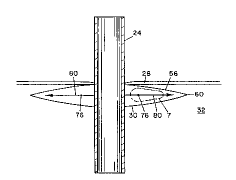
shown for example in Figs. 2 and 4, a conduit 24 extends
through an opening through skin 28 in a living human
being or animal. Conduit 24 comprises a tube or pipe
that also passes through the body's subcutaneous tissue
32. Conduit 24 preferably is formed of a bio-compatible
material such as silicon, titanium, polycarbonate, etc.
Preferably, only the tissue interfacing surface of the
conduit need be formed of a bio-compatible ma,terial.
Accordingly, various composite structures are suitable
as conduits for purposes of the present invention.
The device of the present invention further
includes a main body portion. As embodied herein and
shown in Figs. 1-6 for example, a main body portion 30
is integral with or in contact with the exterior wall of
conduit 24.
200937 1
In further accordance with the present invention, a
flange extends outwardly from the main body portion and
has a free edge. As embodied herein and shown in Figs.
1-6 for example, a flange 56 extends radially outwardly
from main body portion 30 and terminates in a free edge
60. Flange S6 preferably surrounds main body portion 30
and extends radially outwardly therefrom. Main body
portion 30 can be integral with flange 56, as desired.
In further accordance with the present invention,
means are provided for varying the stiffness of
different portions of the flange so that the stiffness
decreases as an imaginary point proceeds from portions
of the flange nearest the main body portion to portions
of the flange nearest the free edge. As embodied herein
and shown in Figs. 2-6, the stiffness of flange 56
preferably decreases gradually as an imaginary point 76
moves in the direction of arrow 80 from the portion of
flange 56 contacting conduit 24 to free edge 60. As
embodied herein and shown in Fig. 2 for example, the
stiffness varying means in a flange having a linearly
decreasing thickness preferably includes a decreasing
density of the flange as the imaginary point moves from
the main body portion to the free edge. As shown in
Fig. 2a for example, the density decreases as one
proceeds from left to right, which corresponds to
movement from the vicinity of conduit 24 toward free
edge 60. This decreasing density results in a decreas-
ing stiffness of the flange. In an alternative embodi-
ment shown in Figs. 6 and 7 for example, flange 56 can
have a uniform thickness and the stiffness varying means
preferably includes a plurality of pores wherein the
volumetric density of the pores increases as an
imaginary point moves from the portion of flange 56
contacting conduit 24 to free edge 60. As shown for
flanges formed of fabric in Figs. 3 and 4 for example,
200937 1
the stiffness varying means preferably includes decreas-
ing thread counts as an imaginary point 76 proceeds from
the main body portion toward free edge 60 of the flange.
In other words, the number of individual thread strands
per square inch of flange decreases as an imaginary
point moves from conduit 24 to free edge 60. As shown
in flanges formed of felt-like fibrous materials in Fig.
5 for example, the stiffness varying means preferably
includes a decreasing packing density of fibers. The
stiffness varying means of the flange also can include a
combination of some of the foregoing structural tech-
niques, such as for example an increasing porosity
within a tapered flange of decreasing density.
As shown schematically by the presence of ever
decreasing numbers of specs of shading in Fig. 2a for
example, the stiffness can be preferably decreased by
linearly decreasing the density of a flange as one
proceeds from the main body portion to the free edge.
As represented schematically in Fig. 7 for example,
alternatively, the stiffness of a flange of uniform
thickness can be decreased by linearly increasing the
number or size of pores as one proceeds from the main
body portion to the free edge.
As an imaginary point moves through the flange, it
encounters different densities of the material forming
the flange. Thus, the local density changes as a
function of the position of the point within the flange.
The combination of the individual local density charac-
teristics constitutes a density profile for the flange.
Similarly, if one provides the material forming the
flange with a plurality of pores, one can use the
porosity characterizing different local positions within
the flange to obtain a porosity profile. In the present
invention, the poEosity profile is such that the volume
of space occupied by the pores increases, preferably
200937 1
linearly, as an imaginary point moves from nearest the
main body portion to the free edge. This can be
accomplished by an increasing number of pores or an
increase in the size of individual pores, or both.
Each of main body portion 30 and flange 56 prefer-
ably is formed of one or more of the following
materials: silicone rubber, polytetrafluoroethylene,
acrylic copolymers cast on polymeric substrates such as
VERSAPOR manufactured by Gelman Sciences of Ann Arbor,
Michigan, polysulfone, polyurethanes, polyethylene, and
nylon. Such materials can be formed with varying
densities and porosities according to known techniques,
and these densities and porosities can be controlled to
optimize them for a preselected degree of stiffness and
a desired flexibility characteristic.
It will be apparent to those skilled in the art
that various modifications and variations can be made in
the present invention without departing from the scope
or spirit of the invention. Thus, it is intended that
the present invention cover the modifications and
variations of this invention provided they come within
the scope of the appended claims and their equivalents.