Sélection de la langue

Search

Sommaire du brevet 2009441 

Énoncé de désistement de responsabilité concernant l'information provenant de tiers

Une partie des informations de ce site Web a été fournie par des sources externes. Le gouvernement du Canada n'assume aucune responsabilité concernant la précision, l'actualité ou la fiabilité des informations fournies par les sources externes. Les utilisateurs qui désirent employer cette information devraient consulter directement la source des informations. Le contenu fourni par les sources externes n'est pas assujetti aux exigences sur les langues officielles, la protection des renseignements personnels et l'accessibilité.

Disponibilité de l'Abrégé et des Revendications

L'apparition de différences dans le texte et l'image des Revendications et de l'Abrégé dépend du moment auquel le document est publié. Les textes des Revendications et de l'Abrégé sont affichés :

  • lorsque la demande peut être examinée par le public;
  • lorsque le brevet est émis (délivrance).
(12) Brevet: (11) CA 2009441
(54) Titre français: CIRCUIT DE COMMANDE/REGULATION ELECTRIQUE POUR CUISINIERE OU RECHAUD
(54) Titre anglais: ARRANGEMENT IN A RANGE OR A COOKING HOB
Statut: Périmé et au-delà du délai pour l’annulation
Données bibliographiques
(51) Classification internationale des brevets (CIB):
  • F24C 07/08 (2006.01)
  • F24C 15/10 (2006.01)
  • G05D 23/19 (2006.01)
  • H05B 03/68 (2006.01)
  • H05B 03/74 (2006.01)
(72) Inventeurs :
  • LJUNGGREN, PER HENRIK (Suède)
(73) Titulaires :
  • AKTIEBOLAGET ELECTROLUX
(71) Demandeurs :
  • AKTIEBOLAGET ELECTROLUX (Suède)
(74) Agent: SMART & BIGGAR LP
(74) Co-agent:
(45) Délivré: 1993-05-18
(22) Date de dépôt: 1990-02-06
(41) Mise à la disponibilité du public: 1990-08-14
Requête d'examen: 1992-05-29
Licence disponible: S.O.
Cédé au domaine public: S.O.
(25) Langue des documents déposés: Anglais

Traité de coopération en matière de brevets (PCT): Non

(30) Données de priorité de la demande:
Numéro de la demande Pays / territoire Date
8900502-9 (Suède) 1989-02-14

Abrégés

Abrégé anglais


A B S T R A C T
An arrangement in a range, a cooking hob or the like having at least one
electrically heated hot plate (11) and/or oven, comprising a manually operable
setting means (13) for the setting of a desired power or temperature for the
hot plate or the oven. A detecting means (15) is arranged to detect changes
in the setting of the setting means. A timing means (16) co-operates with the
detecting means (15) to be activated by the latter. A switching means (17,26)
co-operates with the timing means (16) to disconnect the power to the hot plate
(11) or the oven on the reaching of an end time determined by the timing means,
said timing means being resetted each time the detecting means (15) is activatedand then operated to start counting towards the predetermined end time.

Revendications

Note : Les revendications sont présentées dans la langue officielle dans laquelle elles ont été soumises.


The embodiments of the invention in which an
exclusive property or privilege is claimed are defined as
follows:
1. An arrangement in a range or a cooking hob having at
least one electrically heated hot plate, said arrangement
comprising a manually operable setting means for the
setting of a desired power or temperature for the hot
plate, characterized by a detecting means for detecting
changes in the setting of the setting means, timing means
which cooperate with the detecting means to be activated
by the latter, and a switching means which cooperates with
the timing means to disconnect the power to the hot plate
on reaching an end time determined by the timing means,
said timing means being reset each time the detecting
means is activated to start counting-up towards the
predetermined end time.
2. Arrangement according to claim 1, characterized in
that the end time depends on the power or temperature
setting so that a higher power or temperature results in
a shorter end time.
3. Arrangement according to claim 2, characterized in
that the timing means is arranged to count up from its
reset position towards the longest end time to occur, said
timing means further having a number of outputs
corresponding to the number of end times, a setting
detection means being arranged to detect the power or
temperature setting, said means having a number of outputs
corresponding to the number of power or temperature
settings, each output of the timing means being connected
to an input of an AND-gate, the second input of which
being connected to the corresponding output of said
setting detection means, said outputs of the AND-gates
being connected to an OR-gate, the output of which being
connected to the switching means for the connection and
disconnection, respectively, of the hot plate.

4. Arrangement according to claim 2, characterized in
that a microprocessor is provided to co-operate with the
setting means to connect or disconnect the hot plate via
an electronic switch, said setting means being arranged to
emit to the microprocessor a voltage the magnitude of
which represents the power or temperature setting, the
microprocessor being programmed to detect every change in
the setting of the setting means and to reset the timing
means at the same time as it orders the timing means to
start counting towards an end time determined by the
microprocessor with respect to the magnitude of the
voltage from the setting means, said microprocessor
operating the electronic switch to disconnect the hot
plate in case the setting means is not again operated
before the end time has been reached.

Description

Note : Les descriptions sont présentées dans la langue officielle dans laquelle elles ont été soumises.

-1- %ao~4~
The present invention refers to an arrangement of the
kind indicated in the preamble of the appending claim 1.
In ranges and cooking hobs most often hot plates are
being controlled such that the desired power level is set
by a setting knob and then the power set is operating
until the hot plate is switched off. In certain ranges
and cooking hobs thermostat-controlled hot plates are
provided and in these it will be achieved that the hot
plate cannot assume a dangerously high temperature.
However, in most cases the range is equipped with at least
one high power hot plate, a so-called quick hot plate, and
if forgotten when set at the highest power leve:L the hot
plate can assume very high temperatures which under
certain circumstances may cause fire or result in other
damages.
It is an object with the invention to prevent hot
plates, in particular, from assuming unallowably high
temperatures as a result from the plate being in operation
unattended for a long time.
As embodied and broadly described herein, the
invention provides an arrangement in a range or a cooking
hoh having at least one electrically heated hot plate,
said arrangement comprising a manually operable setting
means for the setting of a desired power or temperature
for the hot plate, characterized by a detecting means for
detecting changes in the setting of the setting means,
timing means which cooperate with the detecting means to
be activated by the latter, and a switching means which
cooperates with the timing means to disconnect the power
to the hot plate on reaching an end time determined by the
timing means, said timing means being reset each time the
detecting means is activated to start counting-up towards
the predetermined end time.
.~

2~034~1
- la -
The invention will now be described in detail in
connection with two embodiments with reference to the
enclosed drawings, in which:
- Fig. 1 schematically shows a cooking hob having
four hot plates;
- Fig. 2 is a schematic diagram of a circuit for the
time-controlled disconnection of a hot plate;
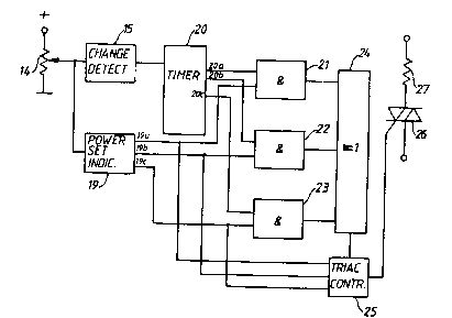
- Fig. 3 is an embodiment according to Fig. 2 which
has been modified to the effect that the time at which the
hot plate is disconnected be varied with respect to the
power level or temperature set; and
- Fig. 4 finally, is a schematic diagram of a
microprocessor-based circuit.
In Fig. 1 a cooking hob 10 is shown having four hot
plates 11 and a panel 12 at the front edge of the hob on
which setting knobs 13 are disposed for the setting of the
desired power level or temperature for the respective hot
plate.
In Fig. 2 a circuit diagram is shown for a device for
the control of a hot plate. In this example the setting
knob acts on a potentiometer 14, the movable terminal of
which being connected to a detector 15 detecting changes
in the setting of the setting knob. Here, the position
set is represented by a voltage the magnitude of which
depends on the position of the movable terminal. The

2(~4~
detector can be of any known type that detects voltage change~. The detector
Is connected to a tlme counting arrangement or tlmer 16 having an output con-
nected to the control electrode of a trlac 17 by whlch the hot plate, here re-
presented by a reslstor 18, can be connected to or disconnected from an AC
mains.
A6 pointed out by way of introduction the object of the inventlon is to
provlde an arrangement by means of whlch it wlll be poss~ble to disconnect
the hot plate In case it has been connected for a con6iderable tlme unattended.
In accordance with the Inventlon this fact Is belng detected by checking of
the settlng knob of the hot plate being operated ~v~thln a predetermlned tlme
period as counted from the very flrst connectlon of the hot plate. At the connec-
tlon of the hot plate the detector 15 is actlvated to emlt a ~gnal to the timer 16
operatlng to reset said timer. Then the t~mer counts up towards an end tlme
corre6pondlng to the expiratlon of the predetermined tlme perlod.
Now, if the setting knob Is again operated before the end tlme has been
reached the detector Is once agaln actlvated to reset the timer. On the contrary,
should no operation of the seeting knob take place before the end tlme has been
reached a signal wlll be emltted at the output of the tlmer ~vhlch wlll operatedthe trlac 17 to dlsconnect the reslstor 18.
Sometimes, In order to further Increase the safety level in case the hot
plate ha~ been 6et for hlgh power, It may be sultable to let the end time dependon the power or temperature settlng so that a higher power ~ettlng corresponds
to a shorter end time. P~g. 3 shows an embodlment In whlch the end t!me can
be varled In the way descrlbed. As In Plg. 2 the settlng knob operates a potentlo-
meter, the output voltage of whlch i6 a measure of the power Ot temperature
6ettlng. Thls is detected In a block 19 having a number of outputs l9a, b, c re-presentlng the respective power or temperature setting.
As In ~Ig. 2 changes In the output voltage of the potentiometer 14 are
detected in a block 15 which represents a detector of changes In the setting
of the ~etting knob. The block 15 i8 connected to a tlmer 20 having outputs 20a,b, c, representlng three dlfferent end tlmes corresponding to the three 6ettlngsof the potentlometer 14 represented on the outputs 19a, b, c. The outpu~s from
the blocks 19 and 20, respectively, are arranged in palrs and connected to threeAND-gate~ 21, 22, 23 so that the outputs l9a, 20a are connected to the
AND-gate 21, the outputs l9b, 20b are connec~ed to the AND-gate 22 and the
outputs 19c, 20c are connccted to the AND-gate 23. Then, the output~ from
the AND-gates 21, 22, 23 are put together in an OR-gate 24 having an output

~ 3 2~0~
connected to a block 25 whlch constitutes a control device for a trlac 26
provided for the connectlon and disconnection, respectlvely, of a resistor 27
wl~ich represents the hot plate.
The circuit dlagram of ~ig. 3 Is a slmple one, the purpo6e of whlch i8 tO
show a solutlon of principle on the problerm relating to different end times.
When the potentiometer 14 has taken its lowest position a mechanical switch,
not shown, assures that the resi6tor 26 is dlsconnected. Then, when the potentio-
meter is operated to a first setting, In a way not shown in detall ~upply voltage
from the mains is applled and the block 19 indlcates on one of its outputs, say
output l9a, the power Ot temperature set. In that way the control devlce 25
Is operated to activate the triac 26 to control, in an on/off control mode, the
heatlng of the resistor 27 in accordance with the ~etting made. At the same
time the detector 13 is activated to emit a signal which reset~ the timer 20.
Said tlmer starts counting up and at the actual end time an output signal Is
to be expected on the output 20a. When the time ha6 expired the AND-gate 21
is activated and hence the OR-gate 2~ whlch ln turn operates the control devlce
to lnactivate the triac 26 to disconnect the resistor 27. Por other power settlngs
the outputs 19b or l9c of block 19 are belng activated and for the correspondingend times the AND-gates 22 or 23 are activated in an analogous manner. The
circult arrangement may be provided with an automatic re~et to the power
setting made but a manual reset i8 preferred.
Pig. 4 show6 an embodiment wherein a microprocessor 2~ has beén u6ed
for the control of the trlac 26. A6 before the potentiometer 14 generate~ a
voltage which represents the power or temperature setting. This voltage as
well as the change~ in it are dlrectly detected by the microprocessor 28 which
co-operate~ with a timer 29 in the same way as described above. Upon changes
in the potentiometer voltage bein8 detected resetting of the timer 29 takes
place and the timer starts counting up from its resetted position. In case a pre-
determined end time 6hould be reached, determined by the microproces60r llvith
respect to the power setting chosen, without the setting knob and accord~ngly
the potentiometer being operated the microprocessor emits a signal which in-
activates the triac 26 causing the resi~tor 27 to be disconnected. Al~o in this
case, suitably, a manually operable resetting means can be provided.

Dessin représentatif
Une figure unique qui représente un dessin illustrant l'invention.
États administratifs

2024-08-01 : Dans le cadre de la transition vers les Brevets de nouvelle génération (BNG), la base de données sur les brevets canadiens (BDBC) contient désormais un Historique d'événement plus détaillé, qui reproduit le Journal des événements de notre nouvelle solution interne.

Veuillez noter que les événements débutant par « Inactive : » se réfèrent à des événements qui ne sont plus utilisés dans notre nouvelle solution interne.

Pour une meilleure compréhension de l'état de la demande ou brevet qui figure sur cette page, la rubrique Mise en garde , et les descriptions de Brevet , Historique d'événement , Taxes périodiques et Historique des paiements devraient être consultées.

Historique d'événement

Description Date
Inactive : CIB de MCD 2006-03-11
Le délai pour l'annulation est expiré 2003-02-06
Lettre envoyée 2002-02-06
Accordé par délivrance 1993-05-18
Exigences pour une requête d'examen - jugée conforme 1992-05-29
Toutes les exigences pour l'examen - jugée conforme 1992-05-29
Demande publiée (accessible au public) 1990-08-14

Historique d'abandonnement

Il n'y a pas d'historique d'abandonnement

Historique des taxes

Type de taxes Anniversaire Échéance Date payée
TM (brevet, 8e anniv.) - générale 1998-02-06 1998-01-20
TM (brevet, 9e anniv.) - générale 1999-02-08 1999-01-19
TM (brevet, 10e anniv.) - générale 2000-02-07 2000-01-19
TM (brevet, 11e anniv.) - générale 2001-02-06 2001-01-18
Titulaires au dossier

Les titulaires actuels et antérieures au dossier sont affichés en ordre alphabétique.

Titulaires actuels au dossier
AKTIEBOLAGET ELECTROLUX
Titulaires antérieures au dossier
PER HENRIK LJUNGGREN
Les propriétaires antérieurs qui ne figurent pas dans la liste des « Propriétaires au dossier » apparaîtront dans d'autres documents au dossier.
Documents

Pour visionner les fichiers sélectionnés, entrer le code reCAPTCHA :


Pour visualiser une image, cliquer sur un lien dans la colonne description du document. Pour télécharger l'image (les images), cliquer l'une ou plusieurs cases à cocher dans la première colonne et ensuite cliquer sur le bouton "Télécharger sélection en format PDF (archive Zip)" ou le bouton "Télécharger sélection (en un fichier PDF fusionné)".

Liste des documents de brevet publiés et non publiés sur la BDBC .

Si vous avez des difficultés à accéder au contenu, veuillez communiquer avec le Centre de services à la clientèle au 1-866-997-1936, ou envoyer un courriel au Centre de service à la clientèle de l'OPIC.


Description du
Document 
Date
(aaaa-mm-jj) 
Nombre de pages   Taille de l'image (Ko) 
Abrégé 1994-07-08 1 16
Revendications 1994-07-08 2 54
Dessins 1994-07-08 2 23
Description 1994-07-08 4 151
Dessin représentatif 1999-07-27 1 9
Avis concernant la taxe de maintien 2002-03-05 1 179
Taxes 1997-01-19 1 69
Taxes 1995-01-18 1 68
Taxes 1996-01-17 1 73
Taxes 1994-01-16 1 65
Taxes 1992-12-10 1 53
Taxes 1992-01-16 1 45
Correspondance de la poursuite 1992-05-28 3 113
Correspondance reliée au PCT 1993-03-09 1 35
Correspondance de la poursuite 1992-07-29 2 57
Courtoisie - Lettre du bureau 1992-06-11 1 38