Note : Les descriptions sont présentées dans la langue officielle dans laquelle elles ont été soumises.
~nog7~9
METHOD AND APPARATUS FOR PRODUCING A WOOD-LIKE
FLAME APPEARANCE FROM A FIREPLACE-TYPE GAS BURNER
This invention relates to flame-coloring devices in
general, and relates more particularly to a device for use in
5gas fireplaces for altering the color and appearance of the
flame to resemble that of the flame produced by burning wood.
Traditional wood-burning fireplaces are enjoyed for their
attractive appearance, the "atmosphere" that their use
creates, and their heat producing ability. However, there
10are many drawbac~s to wood-burning fireplaces, among them the
necessity for cleaning the chimney of soot to prevent chimney
fires, and the build-up of wood ash in the hearth which must
be periodically removed~ In addition, wood for a fireplace
is usually more expensive in urban settings than other fuels,
15such as gas, and it is difficult, or impossible, to install
wood-burning fireplaces in many areas. Furthermore, wood is
not completely combusted in most wood-burning fireplaces, and
this produces ash and soot which enter the atmosphere and
contribute to pollution.
20On the other hand, gas-burning fireplaces can be installed
in a wider variety of locations, burn more efficiently to
produce a greater amount of heat, are easier to maintain,
produce less pollutants, and are less expensive to utilize.
However, the clean, hot flame produced by a gas burner does
25not have the same attractive appearance or provide the warm
glow effect of the yellow/orange colored flame of a
conventional wood-burning fireplace. Furthermore, the burner
2nog7~9
assembly of a gas-burning fireplace is not as attractive as
a pile of wood blazing in the hearth of a wood-burning
fireplace.
In an effort to enable gas-burning fireplaces to have a
closer resemblance to wood-burning fireplaces, Coats, in U.S.
Patent 3,747,585, disclosed a aimulated, noncombustible log
structure supported above the burner of a gas-burning
fireplace. Flames are permitted to contact the underside of
the artificial logs to provide for a more realistic simulation
of a wood-burning fireplace. However, no provision was made
to color or modify the gas flames to resemble those produced
from burning wood.
British Patent No. 12,742, awarded to Oelbermann in 1902,
noted that it was already old to color flames using a great
variety of substances; these include metal salts or ashes,
such as compounds of lithium, strontium, barium, copper,
thorium, cerium, etc. Oelbermann produced a colored flame by
projecting a holder filled with flame-coloring substances into
a candle flame. However, this required an elaborate apparatus
to maintain the holder in the candle flame since the candle
would shrink in height as it was consumed.
Parker et al., in U.S. Patent 4,472,135, improved upon the
teachings of Oelbermann to produce a flame-coloring device for
gas burners which makes the flame visible even when the burner
is used outdoors or in a bright environment. A carrier is
placed on the burner barrel, and a solid colorant emitter such
as sodium chloride is supported by the carrier. However, the
flame-coloring device has only been demonstrated to color
20~)9769
flames of small conventional bunsen type burners.
Furthermore, the colorant emitter used by Parker et al. is not
heat-stable and may become molten at the temperatures employed
to cause the colorant to drip off of the carrier, possibly
clogging the burner and soiling the area surrounding the
burner while also rapidly exhausting the flame colorant.
Salooja, in U.S. Patent 3,925,001 recognized that heat-
stable metal compounds could be used to catalytically improve
the combustion of carbonatious fuels when applied to a support
which is then placed in the center of the primary reaction
zone of a flame. The catalytically active material is
selected from compounds of barium and odium, barium and
yttrium, barium and erbium, aluminum, aluminum and yttrium,
aluminum and lanthanum, aluminum and erbium, aluminum and
platinum, gallium and sodium, zirconium and yttrium, zirconium
and erbium, zirconium and chromium, zirconium and manganese,
zirconium and iron, zirconium and platinum, manganese and
sodium, manganese and yttrium, manganese and titanium,
manganese and chromium, manganese and iron, manganese and
nickel, and palladium and iron.
A critical aspect of Salooja's disclosure is the correct
placement of the catalytically active material in the flame.
Salooja recognized that all gas flames have a general
structure comprised of three zones:
1. A cool zone at the base of the flame where air and fuel
are mixed without substantial fuel combustion;
2. A primary reaction zone, adjacent to the base of the
flame; this is the hottest part of the flame since combustion
2nog769
is most vigorous here and the concentration of ions is at a
maximum; and
3. A secondary reaction zone, above and adjacent to the
primary reaction zone; this is the most luminous part of a
flame, and is usually substantially cooler than the primary
reaction zone. If there is insufficient air, or if combustion
is not complete, smoke and soot would appear above the
secondary reaction zone. Only by placing Salooja's catalyst
impregnated support in the primary reaction zone of a flame
will there be a reduction in the production of soot and smoke
and an increase in the efficiency of flame combustion. The
catalyst impregnated support of Salooja will not work
correctly if placed outside of the primary reaction zone, nor
does it assist in coloring the flame.
Wood-burning flames generally burn cooler than gas flames
and have larger secondary reaction zones due to the incomplete
combustion of the wood components. However, gasburning
fireplaces generally do not suffer from incomplete fuel
combustion, nor do they generate significant quantities of
smoke or soot. In fact, their high temperatures and efficient
utilization of fuel causes the secondary reaction zone of a
gas-burning fireplace flame to be almost invisible. For
example, the primary reaction zone of a natural gas flame
burning in air may achieve temperatures in excess of 3400F
(depending on the fuel to oxidant ratio) while the secondary
reaction zone may have temperatures ranging down to
approximately 1000F.
~()0976~
The high temperatures achieved in a gas-burning fireplace
may pose potential fire and explosion hazards if the fireplace
is not correctly designed and used. As a result, gas-burning
fireplaces should meet appropriate safety standards such as
those set by the American National Standards Institute, ANSI.
Existing flame-coloring methods, if they were to be used in
conjunction with an ANSI approved gas burner, may not be
capable of certification under ANSI or other safety standards.
There is thus a need for a gas-burning fireplace in which
fuel is burned efficiently and cleanly, but which also has a
secondary reaction zone which has the color and appearance of
a wood-burning flame. There is also a need for a device which
can provide uniform flame coloration for extended periods of
time, can be easily replaced, is safe to use, and which has
a flame-coloring substance which will not, when exposed to a
flame, rapidly decompose, or flake and/or drip off to clog the
burner and/or soil the surrounding area. A fireplace using
such a device would combine the economical and improved
heating capabilities of a gas-burning fireplace with the
aesthetic beauty associated with wood-burning fireplaces.
The preferred embodiment of the present invention is
directed to a flame-coloring device which is intended for use
in gas-burning fireplaces. A hollow ceramic tube is provided
as a support for a coating which, when placed in the secondary
reaction zone of a gas-burning fireplace flame, allows for the
controlled release of sodium ions to provide for flame-
coloration. The coated support tube serves to provide a
2no9~69
residence for the flame-coloring coating, and will not
interfere with fuel combustion in the flame; the tube has
mechanical strength at the high operating temperatures of the
flame, and the coating resists degradation, flaking or melting
and consequent running off. The support coating is a mixture
of sodium carbonate (Na26O3) and aluminum oxide (Al2O3) in
pulverized soda lime glass, and sodium metasilicate (Na2SiO3).
The coating may also employ a mixture of sodium bicarbonate
(NaHCO3) in place of, or in combination with, sodium
carbonate; sodium metasilicate may be replaced or combined
with sodium silicate (Na2O.xSiO2 where x = 3-5), hydrated
sodium metasilicate (NaSiO3-9H20) or sodium disilicate
(Na2O.2SiO2). A support made from mullite may be substituted
for the ceramic support.
The coloring compound is applied to the support soon after
its ingredients have been mixed and hydrated. After the
mixture has dried onto the support surface, the coated
supports are baked to bond the composition to the support;
this provides a unique composition which will provide nearly
constant natural color to a gas flame for an extended time
period when the coated support is suspended in the secondary
reaction zone of the flame produced by a burner in a gas
fireplace.
When the flame-coloring device is placed in the secondary
reaction zone, which is located above the primary reaction
zone of a flame, flames contacting the support will excite
sodium atoms and/or other flame-coloring compounds in the
coating so as to release them into the flame where they
2no9769
undergo ionization. When the sodium ions in the flame relax,
they emit light having a specific wavelength characteristic
for sodium and impart a yellow/orange the flame. A variety
of other flame-coloring c such as other metals, metal
compounds and organometallics, may be used as well; the color
of the flame will depend on what coloring compound is used.
The flame-coloring device is designed so as to be nearly
undetectable to the casual observer. The burner and one or
more flame-colorizing tubes may be situated behind and/or
under a decorative, fireproof assembly to hide the burner and
flame-coloring device; for example, a stack of artificial
"logs" made resistant material can be situated in front of and
colorized flame in order for the gas-burning fireplace to more
closely resemble the appearance of a wood fireplace.
Figure 1 is a front elevation view of a first embodiment
of the invention incorporated into a gas-burning fireplace;
Figure 2 is a sectional view of the first embodiment of
the flame-coloring device with a flame impinging upon it taken
along lines 2-2 of Figure l;
Figure 3 is a perspective view of a portion of a second
embodiment of the invention incorporated into a gas-burning
fireplace and including a decorative artificial log assembly;
and
Figure 4 is a partial cross sectional view of the second
embodiment of the invention taken along lines 4-4 of Figure
3.
~6~
Figure 1 illustrates the first embodiment comprising a
flame-coloring device 1 installed in a fireplace 3. A flame
5 is produced by a conventional burner 7 which is located at
a distance beneath flame-coloring device 1. Flame 5 emanates
from holes 9 on burner 7. An igniter (not shown) may be
utilized to automatically light the flame 5, when fuel is
provided to the burner.
With further reference to Figure 2, the flame 5 emanating
from burner 7 has a mixing zone 5M adjacent to gas discharge
holes 9; the mixing zone 5M is generally invisible to the eye
and is the coolest part of the flame. A primary reaction zone
5P is adjacent to and above the mixing zone 5M; due to the
vigorous combustion of the fuel and air mixture, the primary
reaction zone 5P is the hottest part of the flame.
The high temperatures caused by the rapid combustion of the
fuel air mixture generates flame 5 which has a blue color in
the primary reaction zone 5P. A secondary reaction zone 55
surrounds the primary reaction zone 5P, and, due to the almost
complete combustion of fuel in the primary reaction zone 5P,
is almost invisible to the naked eye. By reduction of the
amount of air in the fuel-air mixture, less air is consumed
in the primary reaction zone 5P, and a lower-temperature flame
results. The cooler flame may result in a secondary reaction
zone 55 which has a yellow/orange appearance. However,
producing a colored flame in this manner may lead to
incomplete combustion which wastes fuel, generates less heat,
and pollutes the atmosphere due to the release of incompletely
combusted hydrocarbon materials. It is preferred that the gas
- 2~9769
flame utilized have its fuel to oxidant ratio adjusted so as
to achieve as efficient and complete fuel combustion as
possible.
The flame-coloring device 1 is placed parallel to and above
the burner 7 at a height which allows only the secondary
reaction zone 55 of flame 5 to impinge upon the device 1.
variety of structures that would be obvious to those of skill
in the art can be used to suspend the flamecoloring device 1
above burner 7; for example, a wire - support frame, or the
lo like, could be attached to burner 7 for this purpose. It is
important that the flame-coloring device 1 not be placed into
the primary reaction zone 5P as this may interfere with the
complete and efficient combustion of the fuel and would
accelerate the degradation of the flame-coloring device 1.
The flame-coloring device 1 comprises a coating 11 on a
support 13. The support 13 is a cylindrical ceramic tube
comprised primarily of aluminum oxide (Al203). Aluminum
silicate (also referred to as mullite, 3Al203-2SiO2), or
reticulated silicon carbide (SiC), may substitute for the
ceramic material. Although metals may be used for support
13, they suffer from thermal expansion problems when heated
in the flames, sometimes causing the coating to flake off.
Although a cylindrical tube is the preferred shape for support
13, a variety of shapes and sizes for support 13 may be used
which may be placed in the parallel plane above the holes in
a gas burner so that the coated support is exposed to only the
secondary reaction zone of the flame. Alternatively, a
plurality of flame-coloring compound coated
Z~9~69
supports may be placed in the secondary reaction zone of a
gas-burning fireplace flame.
It is not necessary for the flame-coloring device 1 to be
placed directly in the parallel plane above holes 9 and burner
7 so long as support 13 is located in the secondary reaction
zone 55 of flame 5. An alternative way in which the flame-
colorizing device 1 may be used is for indirect colorization
of flames; this can be achieved by locating support 13 and
flame 5 below or directly adjacent to a second flame (not
shown). Both flames would be colored as their secondary
reaction zones merged. This effect may be enhanced even
further by adjusting flame 5 so that it has a high oxidant to
fuel ratio to produce a tight, well-defined flame pattern.
The second flame (not shown) would be adjusted for low oxidant
to fuel ratio, and would use larger burner ports, to produce
a large fluttering flame.
It should also be noted that holes 9 on burner 7 can be
positioned so that flame 5 projects at an angle from burner
7; this produces a larger secondary reaction zone and more
closely resembles the fluttering irregular flame produced by
a wood-burning fire.
The coating 11 is made from sodium carbonate (Na2CO3) mixed
with aluminum oxide (Al203) in pulverized soda lime glass, and
a warm, saturated sodium metasilicate solution (Na2SiO3). The
resulting solution is applied to ceramic support 13 and baked
at approximately 500F until dry. A support 13 with a coating
11 prepared in this matter may then be placed in the secondary
zn~s769
reaction zone 5S of flame 5 to produce in excess of 1000 hours
of coloration.
Instead of baking the support 13 with coating 11 at
approximately 500F until dry, the coating 11 on support 13
may be dried at 100F. The wet solution applied to the
support 13 is gelatinous in nature and may be dried at
temperatures ranging from room temperature up to approximately
100F to form a coating 11 which is dry to the touch.
However, if a coating 11 on a support 13, which is dried at
these low temperatures, is placed into the secondary reaction
zone 55 of flame 5, without being treated at temperatures in
the range of 200F to 600F first, the coating 11 is likely to
spatter or flake off in the flame 5. Therefore, it is
recommended that the coated supports be treated at
temperatures between the range of 200F and 600F before
exposure to the flame. The spattering from coatings not baked
at 200F to 600F first may be due to the formation of gases
or the rapid loss of water from the coating 11 at higher
temperatures, or is due to a rapid change in molecular
structure.
Coatings applied to support 13, and allowed to dry at room
temperature or at temperatures up to, but not exceeding, 200F
tend to resolubilize in water. However, supports with a
coating baked at temperatures in excess of 200F, especially
at temperatures of approximately 500F, appeared to be
irreversibly dehydrated and did not resolubilize when exposed
to water. Nevertheless, the baked, coated tubes should be
kept free from moisture to avoid flaking problems which may
2~9~69
occur if placed in a flame while still wet. By adjusting the
temperature and time of the bake, it is possible to optimize
the time and temperature parameters for forming a stable
flame-colorizing coating upon a support which will be stable
at the higher operating temperatures of the flames that it is
placed in.
In the alternative, the coating 11 may be formed by adding
sodium bicarbonate (NaHCO3), to a mixture of aluminum oxide
(A12O3), in pulverized soda lime glass. Sodium silicate
solution (Na2O.xSiO2 where x = 3-5) is then added to this
mixture to form a viscous solution. The viscous solution is
then applied to a ceramic or mullite support, which is in the
shape of an elongated tube, and allowed to dry. The coated
support is then baked at 550F for 15 minutes in a vertical
orientation. Standing the tubes in a vertical orientation
helps to provide a uniform coating thickness around the
circumference of the tube while allowing for excess coating
to drip off. By altering the coated tube's position prior to
drying, it is possible to ensure a more uniform coating along
the length of the tube.
Gas-burning fireplaces such as represented here by the
number 3 would generally have the flame-coloring device 1
installed at the factory, and the distance between the burner
7 and flame-coloring device 1 would generally be adjusted upon
its installation in the gas-burning fireplace. Brackets 17a
and 17b are attached to the ends of the flamecoloring device
1 and near the ends of burner 7. The adjustment mechanism is
not shown since any conventional method of adjustably
2(~09769
supporting one object above another may be used. Since the
flame-coloring device uses a hollow support 13, it is also
possible to use brackets which are inserted into the ends of
the supports 13 to hold them up.
Once the fuel-air mix is set in a gas-burning fireplace
with a factory installed flame-coloring device, it is
anticipated that the location of the secondary reaction zone
55 and the primary reaction zone 5P will remain stable, and
not require adjustment of the height of the flame-coloring
device 1 with every use. It is envisioned that suitable
instructions would be included with all such gas-burning
fireplaces 3 with flame-coloring devices 1 to enable a user
to easily adjust the height of the flame-coloring device 1 to
maintain it in the secondary reaction zone 5S.
Care must be taken to keep the flame-coloring device 1 out
of the primary reaction zone 5P, as this will greatly
accelerate the degradation of the coating 11, and may cause
the support 13 to sag or break. Additional brackets (not
shown) may be placed every eight to ten inches along the
support; this may be especially useful for longer
flamecoloring devices.
Flame-coloring compounds have been formulated from the
following ingredients given in their relative weight
percentages:
30-50% soda lime glass,
20-35% aluminum oxide,
5-10% sodium carbonate, and
5-20% sodium metasilicate.
13
ZnQ9~69
Sodium silicate or sodium disilicate may substitute for
sodium metasilicate and sodium bicarbonate may substitute for
sodium carbonate. - Soda lime glass is a glass made by fusing
sand (primarily Sio2) with either sodium carbonate (Na2CO3),
or sodium sulfate (Na2SO4) and calcium carbonate (CaCO3). The
soda lime glass used contained 60-65% silicon dioxide (SiO2),
15-25% sodium oxide (Na2O), and 10-20% calcium oxide (CaO).
However, other percentages may be used depending on the source
of the soda lime glass.
Water is used as a solvent for the sodium metasilicate,
sodium silicate, sodium carbonate and sodium bicarbonate, and
also acts as an application vehicle for the mixture of all the
ingredients. The sodium in the sodium carbonate, sodium
bicarbonate, sodium metasilicate, sodium silicate and the soda
lime glass acts as a sodium ion source, while the soda lime
glass also provides a calcium ion source. The sodium
metasilicate and sodium silicate also act as an adhesive in
the low temperature range. It is believed that some of the
aluminum oxide, which is very slightly soluble in highly
alkaline solutions, may dissolve in the warm, highly alkaline
mixture of the soda lime glass, sodium metasilicate and sodium
carbonate in water. Subsequent recrystalization and baking
of the coating act to create a stronger bond between the
coating and the ceramic or mullite tube. In this manner, the
aluminum oxide may act as a high temperature adhesive and
sodium release moderator; this may also explain the stability
of the flame-coloring compound at the higher temperatures.
2~09~9
When a support 13 with coating 11 is placed into a gas
flame 5, the coating may take on glass like properties and
begin to flow at higher temperatures. Placement of the coated
rod in the primary reaction zone 5P of the flame may cause the
coating to drip off or flake off into the flame 5, thus,
drastically reducing the lifetime of the flamecoloring device
1. The presence of the aluminum oxide in the coating may
provide greater shear strength to the coating to increase its
viscosity at high temperatures. In addition, other more heat-
stable compounds may have been formed between the aluminumoxide and the silicates in the solution, such as sodium
aluminum ortho-silicate (Na2O-Al2O3-2SiO2). The long duration
of the flame-coloring capabilities of the coating in gas
flames may also be explained by the formation of a glass which
slows the rate at which flame-coloring compounds, such as
those containing sodium, are released into the flame.
A number of flame-coloring coatings were formulated and
applied to ceramic and/or mullite tubes. The following are
demonstrative of the large variety of ways in which the flame-
coloring coating may be formulated and used.
Example One
A flame-coloring composition was prepared by adding 2.0
grams of sodium carbonate (Na2CO3), to 10 grams of a 40% by
weight mixture of aluminum oxide (Al2O3), and pulverized soda
lime glass. To this mixture add 10.0 milliliters of a warm
saturated sodium metasilicate solution (Na2SiO3) and 0.1
milliliter glycerine (wetting agent). The mixture was kept
Z~3~976~
,
warm at approximately 150F, applied to a ceramic tube, and
then baked at approximately 500F until dry.
Example Two
A 2 .0 gram quantity of sodium bicarbonate (NaHCO3) was
added to 10 grams of a 50% weight-weight mixture of aluminum
oxide (Alz03) in pulverized soda lime glass. To this mixture,
0.1 milliliter glycerine and 10.0 milliliters of a 40-42 Bé
sodium silicate (Na2O-xSiO2 where x = 3-5) solution we~e
added. The sodium silicate solution used was commercially
available at this concentration, but other concentrations may
be substituted. The resulting gelatinous mixture was applied
to a ceramic or mullite rod, allowed to stand until dry, and
then baked at 5000F for 15 minutes.
EXAMPLE THREE
The solution from Example One and/or the solution from
Example Two was coated upon ceramic and/or mullite tubes, and
the coated supports were then baked at 500F for 15 minutes in
a vertical orientation. Once dry, the tubes were kept away
from moisture.
The coated tubes from example one, two, and three were then
supported above a gas flame burner in the secondary reaction
~one of the flame. When in use, tube temperatures were kept
at about l400F (experimentally measured with a probe inserted
into the tube). It is anticipated that the flame-coloring
tubes will be utilized in the secondary reaction zone of
flames having temperatures, measured from inside of the tubes,
2nos76s
in the range of 1200F to 1600F. Tubes utili~ed in a gas-
burning fireplace in the proceeding manner have provided a
continuous color to gas flames for time periods in excess of
1000 hours. Although it is anticipated that the tubes will
be used in natural gas or propane flames, the device may be
used to color flames produced by other fuels.
In a preferred embodiment, the flam~-coloring coating is
placed on a hollow ceramic (Al2O3) tube having dimensions of
1/4" outer diameter and 1/8" inner diameter; the coating
thickness applied to the ceramic tube may range from
approximately 1/32" to 1/16" thick. The coating is then
dried, baked onto the ceramic tube, and the tube is then
suspended in the secondary reaction zone of the flames in a
gas fireplace. As the flames impede upon the tube, sodium
atoms in the coating are released into the flame where they
are ionized; as the ions relax to lower energy levels, a
characteristic yellow/orange glo~ is given off. The invention
provides this color in a controlled fashion in order to
provide nearly constant natural color for an extended time
period. This extended life is due to the unique composition
of flame-coloring compound.
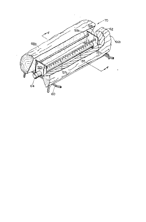
With further reference to Figures 3 and 4, a second
embodiment of a gas flame-coloring device 70 is disclosed. Gas
flame-coloring device 70 is shown incorporating two flame-
colorizing tubes 59a and 59b which are held by two rectangularbrackets 52a and 52b above burner element 55. Burner element
55 is an elongated hollow cylinder, and is fed fuel through
gas inlet 62. Fuel fed to element 55 is blocked at the
znos769
opposite of inlet 62 by detachable end cap 64. Cap 64 may be
permanently attached or the end of element 55 may be sealed
in any other suitable fashion.
The tubes 59a and 59b may simply rest in the holes 52c and
52d provided in brackets 52a and 52b, or the tubes 59a and
59b may be connected by an alternative means to prevent the
tubes from sliding in the bracket holes 52c and 52d.
Brackets 52a and 52b may be attached to element 55 by
removing end cap 64, and 'then sliding brackets 52a and 52b
onto element 55. Brackets 52a and 52b may be welded in place,
or they may have a snug enough fit on burner element 55 so
that they project upwardly above burner element 55 in a fixed
position. This same result may be achieved by fitting
brackets 52a and 52b over protuberances, or into recesses, on
burner element 55.
Holes 52c and 52d- are shown having fixed locations in the
rectangular brackets 52a and 52b as the brackets 52a and 52b
are designed to be installed at the factory which produces the
gas-burning fireplace; since the burner 55 is preadjusted at
the factory, brackets 52a and 52b will hold the flame-
colorizing tubes 59a and 59b in the secondary reaction zone
55 of a flame produced by burner 55.
It is envisioned that a wide variety of brackets may be
used to support the flame-coloring tubes in the secondary
reaction zone of a flame. Adjustable brackets can be used
since it may be necessary to adjust the height of the
flamecolorizing tubes 59a and 59b above the burner element 55
to maintain the tubes 59a and 59b in the secondary reaction
-` 200976~
zone of the flame. This is especially important for gas
burning fireplaces which are not assembled at a factory, or
when the flame-coloring device of the present invention is
retrofitted to an existing gas burner.
5Gas flame-coloring device 70 rests upon fireplace grate 60.
The coloring device 70 may be partially or completely hidden
from view by a decorative, fireproof assembly such as
artificial logs 66a and 66b. Artificial logs 66a and 66b can
be made of concrete, ceramic fibers, or any suitable flame
10resistant material. Logs made from a mixture of sand, gravel,
and portland cement have been used with satisfactory results.
When flame-coloring device 70 is concealed by logs 66a and
66b, it may be necessary to increase the flame size. This can
be done by increasing input rate and/or the port area on the
15burners used. The larger burners may be necessary for a
uniform flame pattern if input rate and port area requirements
exceed burner capacity. Note that high port loading results
in a long, fluttering flame. However, if port loading is too
high, flame lifting, yellow tipping, unacceptable combustion,
20and unreliable ignition might occur. The aesthetic and
operational characteristics of the flame can be optimized by
varying the number and size of burner ports for a given port
area. It is also noted that a small number of large ports
provide a larger, fluttering flame which is similar to that
25produced by burning wood, while a large number of small ports
provide a short, but well defined, relatively stable flame.
However, when using a large number of small ports, there is
less chance of flashback, flame lifting, and yellow tipping.
19
20~:)97~9
Of course, in order for the flame to have an acceptable
carryover between ports so that a uniform elongated flame is
formed, it will be necessary to have the ports sufficiently
close together.
With further reference to Figure 4, it can be seen that
two rows of ports 57a and 57b are located along the
circumference of element 55. Flames 65a and 65b project from
ports 57a and 57b. Flames 65a and 65b project from element
55 at an angle, causing the flames 65a and 65b to bend upwards
under the influence of their natural buoyancy so as to
respectively engage 59a and 59b. The secondary reaction zone
65s of flames 65a and 65b contact flame-coloring tubes 59a and
59b.
The separation of ports 57a and 57b on the circumference
of element 55 can be determined by the angle between two
imaginary planes which emanate from the axis 0 of element 55
and which intersect the wàll 54 of element 55 at ports 57a and
57b. For example, an angle of 900 between the two planes
would separate their points of intersection with wall 54 by
one-fourth of the circumference of element 55.
Generally, element 55 will be situated so an imaginary
vertical plane passing through axis 0 will bisect the angle
between the forementioned planes which meet at axis 0; in
other words, ports 57a would be located on one side of the
vertical plane passing through axis 0 and ports 57b will be
on the opposite side of the vertical plane from ports 57a and
the distance between one vertical pla~e passing through axis
0 and ports 57a is equal to the distance between the vertical
2(30~769
plane passing through axis 0 and parts 57b. The angle between
the imaginary planes emanating from axis 0 and passing through
ports s7a and s7b determines the angle at which flames will
emanate from element 55.
5Tubes 59a and 59b are laterally offset outwards from the
imaginary vertical planes which pass through ports 57a and 57b
so that tubes 59a and 59b remain in the center of the
secondary reaction zone 65s of flames 65a and 65b. Secondary
reaction zone 65s of flames 65a and 65b may also contact
10artificial logs 66a and 66b. The secondary reaction zones 65s
of flames 65a and 65b which contact artificial logs 66a and
66b should already be colored due to its contact with tubes
59a and 59b; logs 66a and 66b further disburse the secondar,v
reaction zone 65s in order to give flames 65a and 65b an
15appearance very similar to a flame produced by burning wood.
The size of flames 65a and 65b may be adjusted by
controlling the amount of fuel entering element 55 through
gas inlet 62, altering the size of ports 57a and 57b,
adjusting the oxidant to fuel ratio, or changing the angle at
20which ports 57a and 57b project flames 65a and 65b from
element 55.
A gas burner for use with the flame-coloring device of the
present invention has been constructed using a 3/4" nominal
black iron pipe. Two rows of 36 ports each are located on the
25upper circumference of the pipe with the two rows separated
by a distance equal to one- fourth of the circumference
(determined by the intersections of two imaginary planes with
2o09769
the pipe circumference which also have a 90 angle of
intersection with each other at the pipe axis).
Each port has an area of approximately 0.00528"2. A
suitable flame was produced when the burner had an input rate
of 60,000 BTU/hour and a port loading of 158,000 BTU"2. It is
envisioned that burners made from other materials and having
a wide variety of shapes and sizes may also be used with the
gas flame-colorizing device. In addition, the number and size
of ports may vary, or the ports may be replaced with one or
more slots.
When flame-coloring device 70 is used in the manner
described, a casual observer might easily confuse a fireplace
utilizing the device with a wood-burning fireplace.
Although the preferred embodiments have been described and
illustrated herein, it will be understood that various
alterations, modifications and substitutions may be apparent
to one of skill in the art without departing from the
essential spirit of the invention. The scope of the invention
is accordingly defined by the following claims.
- . .