Sélection de la langue

Search

Sommaire du brevet 2009861 

Énoncé de désistement de responsabilité concernant l'information provenant de tiers

Une partie des informations de ce site Web a été fournie par des sources externes. Le gouvernement du Canada n'assume aucune responsabilité concernant la précision, l'actualité ou la fiabilité des informations fournies par les sources externes. Les utilisateurs qui désirent employer cette information devraient consulter directement la source des informations. Le contenu fourni par les sources externes n'est pas assujetti aux exigences sur les langues officielles, la protection des renseignements personnels et l'accessibilité.

Disponibilité de l'Abrégé et des Revendications

L'apparition de différences dans le texte et l'image des Revendications et de l'Abrégé dépend du moment auquel le document est publié. Les textes des Revendications et de l'Abrégé sont affichés :

  • lorsque la demande peut être examinée par le public;
  • lorsque le brevet est émis (délivrance).
(12) Demande de brevet: (11) CA 2009861
(54) Titre français: OUTIL DE FORAGE
(54) Titre anglais: DRILL BIT
Statut: Réputée abandonnée et au-delà du délai pour le rétablissement - en attente de la réponse à l’avis de communication rejetée
Données bibliographiques
(51) Classification internationale des brevets (CIB):
  • E21B 10/00 (2006.01)
  • E21B 10/38 (2006.01)
  • E21B 17/00 (2006.01)
  • E21B 21/16 (2006.01)
(72) Inventeurs :
  • LARSSON, LARS K. (Suède)
  • LILJEBRAND, SVEN P. (Suède)
(73) Titulaires :
  • SANDVIK AB
(71) Demandeurs :
  • SANDVIK AB (Suède)
(74) Agent: GOWLING WLG (CANADA) LLP
(74) Co-agent:
(45) Délivré:
(22) Date de dépôt: 1990-02-12
(41) Mise à la disponibilité du public: 1990-08-13
Licence disponible: S.O.
Cédé au domaine public: S.O.
(25) Langue des documents déposés: Anglais

Traité de coopération en matière de brevets (PCT): Non

(30) Données de priorité de la demande:
Numéro de la demande Pays / territoire Date
8900473-3 (Suède) 1989-02-13

Abrégés

Abrégé anglais


ABSTRACT OF THE DISCLOSURE
The present invention relates to a drill bit (11) intended to
be included in a drill string (10) for top hammer drilling,
said drill string (10) including a set of central rod members
(12) for transferring impact energy to the drill bit (11) and
a set of tubular members (13) surrounding the set of rod
members (12) for transferring rotation to the drill bit (11).
The invention also relates to a tubular member (13b) and to a
drill string (10). In drilling equipments of the type
mentioned above it is favourable - especially for greater
diameters, preferably above 125 mm - to guide the flushing
medium in an internal channel in the set of rod members (12).
In order to guarantee lubrication of the splines coupling
(14) through the lubricant that is mixed into the flushing
medium, an intermediate section (16a) of the drill bit (11)
is provided with branch channels (16c, 16d) to discharge the
flushing medium to and from a recess (18) in the space
between the drill bit (11) and the set of tubular members (13).

Revendications

Note : Les revendications sont présentées dans la langue officielle dans laquelle elles ont été soumises.


The embodiments of the invention in which an exclusive
right or privilege is claimed are defined as follows:
1. Drill bit intended to be included in a drill
string for top hammer drilling, said drill string including a
set of central rod members for transferring impact energy to
the drill bit and a set of tubular members surrounding the
set of rod members for transferring rotation to the drill
bit, characterized in that the drill bit has a central
longitudinal flushing medium channel, and that at least one
transverse channel is provided in an intermediate section of
the drill bit, said transverse channel being connected to the
central flushing medium channel and perforating the envelope
surface of the drill bit.
2. Drill bit according to claim 1, characterized in
that the portions of the central flushing medium channel
located axially on each side of the intermediate section have
at least one branch channel each, said branch channels
constituting the transverse channels in the intermediate
section.
3. Drill bit according to claim 1, characterized in
that the central flushing medium channel is through-going and
has a throttling in the intermediate section, and that a
portion of the channel located upstream of the throttling has
a greater cross section area than a portion of the channel
located downstream of the throttling, said transverse channel
being connected to the portion located upstream of the
throttling.
4. Drill bit according to claim 4, characterized in
that the drill bit is in separate pieces, said pieces resting
loosely against each other.
5. Drill bit according to claim 4, characterized in
that a parting plane is located between the intermediate
section and the front face of the drill bit.

6. A tubular member included in a set of tubular
members, said set being intended to be included in a drill
string for top hammer drilling, said drill string including a
set of central rod members for transferring impact energy to
the drill bit, and the set of tubular members surrounding the
set of rod members for transferring rotation to the drill
bit, characterized in that the tubular member has an internal
recess.
7. Drill string for top hammer drilling including a
drill bit and a set of central rod members for transferring
impact energy to the drill bit and a set of tubular members
surrounding the set of rod members for transferring rotation
to the drill bit, characterized in that the set of central
rod members has a central, longitudinal, continuous flushing
medium channel, and that the drill bit has a central,
longitudinal flushing medium channel and that in an
intermediate section of the drill bit at least one transverse
channel is provided, said channel being connected to the
central flushing medium channel and perforating the envelope
surface of the drill bit, and that axially in the level with
the transverse channel the set of tubular members is provided
with an internal recess.
8. Drill string according to claim 7, characterized
in that the portions of the central flushing medium channel
of the drill bit located on each side of the intermediate
section have at least one branch channel each, said branch
channels constituting the transverse channels in the
intermediate section.
9. Drill string according to claim 8, characterized
in that the branch channels are inclined relative to the
longitudinal centre axis of the drill bit.
10. Drill string according to any one of claims 7, 8
or 9, characterized in that the drill bit is in separate

pieces and in the area of the intermediate section has a
travel limiter that is intended to cooperate with the set of
tubular members to provide a limited axial displacement of
the upper piece of the drill bit relative to the set of
tubular members.

Description

Note : Les descriptions sont présentées dans la langue officielle dans laquelle elles ont été soumises.

Z0~9861
Drill bit
The present invention relates to a drill bit that is
intended to be included in a drill string for top hammer
drilling. Said drill string includes a set of central rod
members for transferring impact energy to the drill bit and
a set of tubular members surrounding the set of rod members
for transferring rotation to the drill bit. The invention
also relates to a tubular member and a drill string.
1 0 ,~ "", j ,,
, From US-A-4,094,364 a device of the above mentioned kind is
-i previously known. The set of central rod members consists of
preferably massive rods and flushing medium is fed to the
drill bit via an annular space between the set of rod
members and the set of tubular members. The drill bit is
closed at its rear impact-receiving end. The reason for this
structural design is that the transferring surface of the
rods and the drill bit for the impact energy must be
sufficiently big in order to make possible the use of a top
hammer equipment having such a high effect that a satisfying
drill penetration rate is achieved. For bigger drill hole
diameters, especially exceeding 125 mm, the rod members of
the set also get a bigger diameter and thereby the cross-
section area of the rod members become sufficient even if an
internal flushing channel is arranged. However, an internal
flushing chan~el provides unsufficient lubrication of the
splines coupling between the drill bit and the tubular
member and furthermore there is a risk, due to jet action,
that cuttings (crushed rock) are sucked in between the drill
bit and the tubular member at the front of the drill bit .
The aim of the present invention is to disclose a drill bit
and a tubular member included in a drill string as described
above, said drill bit and the tubular member in cooperation
eliminating the problems discussed above.
The present invention is realized by a drill bit, a tubular
member and a drill string that have been given the

Z0098~1
characteristics of the appending claims.
Below an embodiment of the invention will be described,
reference being made to the accompanying drawings, where
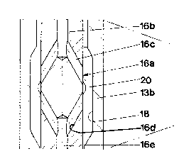
Fig.l shows a partly sectioned side view of a drill string
according to the invention; Fig.2 shows a detail of the
drill string according to Fig.l; and Fig.3 shows a detail of
an alternative embodiment of the invention.
Fig.l shows the lower portion of a drill string 10 including
a drill bit 11 according to the present invention. In the
shown embodiment the drill bit 11 is in separate pieces lla
and llb, said pieces resting loosely against each other.
However, within the scope of the invention it is also
possible to have an integral drill bit.
The upper portion llb of the drill bit 11 is brought in
contact with the lowest rod 12a of the central set of rod
members 12 that transfers impact energy from the top hammer
to the drill bit 11. The lower end of the rod 12a rests
loosely against the upper end of the upper piece llb.
The set of tubular members 13 surrounding the set of rod
members 12 and the drill bit 11 transfers rotation from the
top hammer equipment to the drill bit ll. This is effected
inter alia by a splines coupling 14 between the lowest
tubular member 13a of the set of tubular members 13 and the
drill bit 11. The tubular members of the set of tubular
members 13 are connected by thread couplings 15.
As is apparent from Fig.l the drill bit 11 is provided with
a substantially central flushing medium channel 16. The set
of central rods 12 has a centrally running flushing medium
channel 17.
In the upper piece llb of the drill bit 11 the substantially
central flushing medium channel 16 has an intermediate
section 16a that is shown in detail in Fig.2. Said section

3 20G986~
16a is located above the splines coupling in Fig.l. As is
apparent from Fig.2 a portion 16b extending from above of
the central flushing medium channel 16 is divided into two
branch channels 16c that are inclined relative to the
longitudinal centre axis of the flushing medium channel 16.
The branch channels 16c perforate the envelope surface of
the upper piece llb and emerge in an internal recess 18 in a
surrounding tubular member 13b of the set of tubular members
13.
From the recess 18 two further branch channels 16d extend to
a downwards directed portion 16e of the central flushing
medium channel 16, said two branch channels 16d also being
inclined relative to the longitudinal centre axis of the
flushing medium channel 16.
The central flushing medium channel 16 extends through the
lower piece lla of the drill bit 11 and emerge via discharge
channels 16f in the front face 19 of the drill bit 11.
The above described structural design of the drill bit 11
functions in the following way.
The flushing medium i8 normally air having a mixed in
lubricant, e.g. in the form of oil. When the flushing medium
flowing towards the drill bit 11 passes the section 16a of
the central flushing medium channel 16, said flushing medium
will via the branch channels 16c emanate into the recess 18
and from there via the branch channels 16d to the downwards
directed portion of the central flushing medium channel 16
to continue towards the front face 19 of the drill bit 11.
When the flushing medium passes the recess 18 lubricant will
adhere to the surfaces of the recess 18 and then said
lubricant will trickle down into the space between the
drill bit 11 and the set of tubular members 13. This means
that the splines coupling 14 between the lower piece lla of
the drill bit 11 and the lowest tubular member 13a of the
set of tubular members 13 automatically gets a proper

4 200986~
lubrication.
A further advantage of the structural design according to
the present invention is that a pressure equalization takes
place regarding the central flushing medium channel 16 and
the space between the lower piece lla of the drill bit 11
and the lowest tubular member 13a of the set of tubular
members 13. Since the pieces lla and llb resp. of the drill
bit 11 loosely rest against each other with an accompanying
play, jet action from the flowing flushing medium might
create a certain partial vacuum between the drill bit 11 and
the set of tubular members 13. Such a partial vacuum could
lead to that cuttings being sucked in from below between the
lower piece lla of the drill bit 11 and the lowest member
13a of the set of tubular members 13. This would inter alia
damage the splines coupling 14. The arrangement of the
section 16a eliminates the risk for creation of a partial
vacuum of the type described.
In the area of the section 16a the upper piece llb of the
drill bit 11 is provided with a travel limiter 20 preventing
said piece from sliding out when the lower piece lla of the
drill bit 11 is removed for exchange or service.
The alternative embodiment of Fig.3 includes a through-going
central flushing medium channel 16 being provided with a
throttling 21. The portion 16g in Fig.3 located above the
throttling 21 of tha flushing medium channel 16 has a
bigger diameter than the portion 16h of the flushing medium
channel 16 located below the throttling 21.
Before the throttling 21, seen in the direction of flow of
the flushing medium, a transverse channel 22 is provided.
Said channel 22 extends from the portion 16g of the flushing
medium channel 16 and pen~trates the envelope surface of the
drill bit 11. The transverse channel 22 emanates in an
internal recess 18 in a surrounding tubular member 13b of
the set of tubular members 13.

20~3986~
The structural design shown in Fig.3 functions in principle
as the embodiment described in connection with Figs.1 and 2.
The invention is in no way restricted to the embodiments
described above but can be freely varied within the scope of
the appending claims.

Dessin représentatif
Une figure unique qui représente un dessin illustrant l'invention.
États administratifs

2024-08-01 : Dans le cadre de la transition vers les Brevets de nouvelle génération (BNG), la base de données sur les brevets canadiens (BDBC) contient désormais un Historique d'événement plus détaillé, qui reproduit le Journal des événements de notre nouvelle solution interne.

Veuillez noter que les événements débutant par « Inactive : » se réfèrent à des événements qui ne sont plus utilisés dans notre nouvelle solution interne.

Pour une meilleure compréhension de l'état de la demande ou brevet qui figure sur cette page, la rubrique Mise en garde , et les descriptions de Brevet , Historique d'événement , Taxes périodiques et Historique des paiements devraient être consultées.

Historique d'événement

Description Date
Inactive : CIB de MCD 2006-03-11
Inactive : Abandon.-RE+surtaxe impayées-Corr envoyée 1997-02-12
Inactive : Demande ad hoc documentée 1997-02-12
Le délai pour l'annulation est expiré 1994-08-13
Demande non rétablie avant l'échéance 1994-08-13
Réputée abandonnée - omission de répondre à un avis sur les taxes pour le maintien en état 1994-02-14
Inactive : Demande ad hoc documentée 1994-02-14
Demande publiée (accessible au public) 1990-08-13

Historique d'abandonnement

Date d'abandonnement Raison Date de rétablissement
1994-02-14
Titulaires au dossier

Les titulaires actuels et antérieures au dossier sont affichés en ordre alphabétique.

Titulaires actuels au dossier
SANDVIK AB
Titulaires antérieures au dossier
LARS K. LARSSON
SVEN P. LILJEBRAND
Les propriétaires antérieurs qui ne figurent pas dans la liste des « Propriétaires au dossier » apparaîtront dans d'autres documents au dossier.
Documents

Pour visionner les fichiers sélectionnés, entrer le code reCAPTCHA :


Pour visualiser une image, cliquer sur un lien dans la colonne description du document. Pour télécharger l'image (les images), cliquer l'une ou plusieurs cases à cocher dans la première colonne et ensuite cliquer sur le bouton "Télécharger sélection en format PDF (archive Zip)" ou le bouton "Télécharger sélection (en un fichier PDF fusionné)".

Liste des documents de brevet publiés et non publiés sur la BDBC .

Si vous avez des difficultés à accéder au contenu, veuillez communiquer avec le Centre de services à la clientèle au 1-866-997-1936, ou envoyer un courriel au Centre de service à la clientèle de l'OPIC.


Description du
Document 
Date
(aaaa-mm-jj) 
Nombre de pages   Taille de l'image (Ko) 
Dessins 1990-08-13 2 34
Revendications 1990-08-13 3 86
Abrégé 1990-08-13 1 23
Page couverture 1990-08-13 1 12
Description 1990-08-13 5 177
Dessin représentatif 1999-07-29 1 8
Taxes 1992-12-23 1 89
Taxes 1991-12-24 1 74