Note : Les descriptions sont présentées dans la langue officielle dans laquelle elles ont été soumises.
Docket 4470
2~{)327
STRIP FEED ROLI,ER
Background of The Invention
_ _
A strip feed roller or cylinder is employed
in moving strip material, such as paper or paper-like
material or fabric material or the like. A strip feed
5 roller or cylinder may be a portion of a strip or web
or sheet folder machine or the like. In most situations, -
a strip feed roller or cylinder must be one which moves
strip material accurately, without slippage longitudinally,
without slippage laterally, and without slippage angularly.
~ In attempts to provide a strip feed roller
which maintains extreme accuracy, without slippage, some
strip feed rollers have firm, rigid grasping surfaces.
Such sùrfaces have been found to cut into the strip.
Some~str1p feed rollers have been found to cause smudg-
15~1ng i~n pressure sensitive copy paper. Therefore, suchstrip feed rollers are not acceptable.
United States-Patents 241,461, 709,694, -~
3,060,545, 3,240,442, and 3,447,221 disclose strip feed
rollers and mechanisms. However, so far as is known,
20 the rollers and m'echlanisms disclosed in these patents ! ~ - ~;`".,',.",~ ,'.`.'
do not contain the details of the structure of this
invention.
It is therefore an object of this invention -~
to provlde a strip feed roller or cylinder which is -~
25 capable of extreme accuracy in strip feeding.
:3 , ; ' ~
-2- 2 ~ ~ ~ 3 2
It is another object of this invention to pro-
vide such a strip feed roller which does not cut into
the strip and which does not cause smudging in pressure
sensitive copy paper.
Other objects and advantages of this inven-
tion reside in the construction of parts, the combina-
tion thereof, the method of production and the mode of
operation, as will become more apparent from the follow-
ing description.
Summary of The Invention
This invention comprises a strip feed roller
or cylinder which is particularly created for accurate
and precise feeding of paper or paper-like material.
However, a strip feed roller or cylinder of this inven-
tion may be employed in feeding or moving strips of
other materials. The strip feed roller of this inven-
~; tion is one which accurately feeds paper or paper-like
material or other relatively soft materials but does
not cause cutting of the paper or material and which -~
does not cause bursting or fracturing of capsules in
carbonless copy paper.
~` A strip feed roller of this invention comprises
an elongate cylindrical member which is preferably of
a rigid material, such as metallic material or rigid
-~ 25 plastics material, or other rigid material. The cylin-
drical member is knurled or grooved. Thus, initially
the surface of the roller has alternate grooves and teeth. ;
In the production of a s~trip feed roller of this inven-
tion, the grooves between the teeth in the cylindrical
~ 30 member or roller are filled with rubber material or
`~ rubber-like plastics material, such as urethane. Then
`~ the surface of the roller is cut to form a cylinder of
constant diameter throughout its length, and thus the
roller has a smooth cylindrical surface. In the cutting
of the surface only a small portion of each tooth is
'",
,~
20~0327
--3--
exposed on the cylindrical surface. Thus, the roller
has a cylindrical surface which has alternate axially
extending narrow sections of rigid material and alternate
axially extending narrow sections of resilient material.
Therefore, when a strip feed roller of this
invention is employed in feeding a strip of material,
such as a strip of paper or paper-like material, the
paper is alternately engaged by the rigid teeth and
alternately engaged by the resilient material, which
is positioned between the teeth. The narrow rigid sec-
tions formed by the teeth provide a firm grip upon the
paper, and the narrow resilient sections between the
rigid teeth prevent deformation of the surface of the
paper and thus prevent damage to the paper. The narrow
resilient sections also engage the paper and serve as
feed elements for movement of the paper.
The narrow resilient sections aid in paper
feed action and also prevent damage to the paper. The
narrow resilient sections prevent slippage of the paper
20 laterally, longitudinally, and angularly. Therefore, -~
the narrow rigid sections formed by the teeth and the
narrow resilient sections formed by the urethane material
combine to accurately move any type of paper or other
strip material without cutting, creasing or smudging
- 25 of the strip material.
In a typical strip feed situation two or more
: .
~; strip feed rollers of this invention are in juxtaposed
parallel relationship and engage paper which is positioned
between the rollers.
Brief Description of The Views of The Drawings
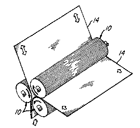
FIG. 1 is a perspective view illustrating a
; plurality of strip feed rollers of this invention in ~ ;
engagement with a strip of paper in a folding operation. - ~;~
', ~ .: '' '
: :'., , '
2~0327
--4--
FIG. 2 is a perspective view with parts broken
away and shown in section, showing a strip feed roller
of this invention. This view is drawn on a much larger
scale than FIG. 1.
FIG. 3 is an enlarged fragmentary sectional
view taken substantially on line 3-3 of FIG. 2. This
view shows the surface of the roller prior to completion
of processing the surface of the roller.
FIG. 4 is an enlarged fragmentary sectional
view, drawn on the same scale as FIG. 3, and showing
the surface of the strip feed roller following process-
ing thereof.
FIG. 5 is an enlarged fragmentary sectional
view, drawn on a larger scale than FIG. 4, showing a
portion of the strip feed roller illustrated in FIG.
4.
FIG. 6 is a diagrammatic sectional view, drawn
on a smaller scale than FIG. 4, showing two strip feed
rollers of this invention and illustrating a portion
of a strip of material as the strip is moved by rota-
tion of the rollers.
Detailed Description of_The Preferred Embodiment
FIG. 1 shows a plurality of strip feed rollers
or cylinders 10 of this invention. In FIG. 1 the rollers
10 are shown as being arranged for feeding a strip 14
of paper in a folding operation.
FIG. 2 shows, in greater detail, one of the
strip feed cylinders 10.
FIGS. 3, 4, and 5 show, in still greater detail,
portions of a strip feed cylinder or roller 10 of this
invention.
A basic strip feed roller 10 is preferably
composed of relatively hard material, such as metallic
material or the like. In production, the roller 10 is
knurled, or otherwise formed, to produce a multiplicity
of axially extending teeth 20 and valleys 22, in alternate
2~03~7
positions, as shown in FIG. 3. Then the surface of the
roller 10 is covered with a rubber or rubber-like material,
such as urethane 30 or the like, as the valleys 22 are
filled with the urethane material. Preferably, the
urethane material has a durometer value in the range
of about 65 to 75.
Then the surface of the roller 10 is cut to
form a cylindrical surface of constant diameter along
the length of the cylinder. The surface is cut to reduce
the diameter of the roller and to expose only the upper
portion of the teeth 20. In the cutting of the surface
of the roller, the peaks of the teeth 20 are removed.
Thus, as shown in FIGS. 4 and 5, each tooth 20 presents
a narrow exposed surface which forms an axially extending
narrow rigid section at the surface of the cylinder 10.
Between adjacent teeth 20 is an axially extending narrow
section of urethane material 30. The teeth 20 and the ;~
urethane material 30 form a smooth cylindrical surface -
upon the roller 10. Thus, there are alternate narrow
rigid sections and alternate narrow resilient sections
at the surface of the roller 10, as illustrated in FIGS.
4, 5, and 6. Due to the fact that each rigid section
and each resilient section is a part of the cylindrical
surface, each narrow rigid section and each narrow re-
25 silient section is slightly arcuate across the width ;~
thereof. .-
Therefore, as each cylinder or roller 10 rotates i~
and engages a strip 14, in a manner such as illustrated ; i
in FIGS. 1 and 6, the strip 14 is accurately and precisely
moved. The rigid metallic surface of the teeth 20 provide
firm gripping of the strip 14. The narrow sections of
urethane material 30 provide a cushioned surface for
movement of the strip 14, and prevent creasing and wrin-
kling and/or cutting of the strip 14. The cylinders
35 10, which include the combined alternate narrow rigid ~ "
surfaces and narrow resilient surfaces, accurately move
2~10327
. ~
-6-
the strip 14, or any strip, without lateral, or angular,
or longitudinal slippage. When the strip 14, shown
in FIGS. 1 and 6, comprises pressure sensitive carbonless
copy paper, the paper does not smudge as it is moved
by the cylinders 10.
Although the preferred embodiment of a strip
feed roller of this invention has been described, it
will be understood that within the purview of this inven-
tion various changes may be made in the form, details,
proportion and arrangement of parts, the combination
thereof, and the mode of operation, which generally stated
consist in a structure within the scope of the appended
claims.
.
- ' ::.
' ~
:
:~ ~