Sélection de la langue

Search

Sommaire du brevet 2011158 

Énoncé de désistement de responsabilité concernant l'information provenant de tiers

Une partie des informations de ce site Web a été fournie par des sources externes. Le gouvernement du Canada n'assume aucune responsabilité concernant la précision, l'actualité ou la fiabilité des informations fournies par les sources externes. Les utilisateurs qui désirent employer cette information devraient consulter directement la source des informations. Le contenu fourni par les sources externes n'est pas assujetti aux exigences sur les langues officielles, la protection des renseignements personnels et l'accessibilité.

Disponibilité de l'Abrégé et des Revendications

L'apparition de différences dans le texte et l'image des Revendications et de l'Abrégé dépend du moment auquel le document est publié. Les textes des Revendications et de l'Abrégé sont affichés :

  • lorsque la demande peut être examinée par le public;
  • lorsque le brevet est émis (délivrance).
(12) Brevet: (11) CA 2011158
(54) Titre français: PINCES POUR RAIL
(54) Titre anglais: TRACK CLAMP ASSEMBLY
Statut: Réputé périmé
Données bibliographiques
(52) Classification canadienne des brevets (CCB):
  • 238/156
(51) Classification internationale des brevets (CIB):
  • E01B 9/00 (2006.01)
  • E01B 25/24 (2006.01)
(72) Inventeurs :
  • MCDONALD, CLAYTON C. (Etats-Unis d'Amérique)
  • DUCZKOWSKI, EDWARD M. JR. (Etats-Unis d'Amérique)
(73) Titulaires :
  • JERVIS B. WEBB COMPANY (Etats-Unis d'Amérique)
(71) Demandeurs :
(74) Agent: RIDOUT & MAYBEE LLP
(74) Co-agent:
(45) Délivré: 1999-03-30
(22) Date de dépôt: 1990-02-28
(41) Mise à la disponibilité du public: 1990-09-06
Requête d'examen: 1993-11-24
Licence disponible: S.O.
(25) Langue des documents déposés: Anglais

Traité de coopération en matière de brevets (PCT): Non

(30) Données de priorité de la demande:
Numéro de la demande Pays / territoire Date
07/319,544 Etats-Unis d'Amérique 1989-03-06

Abrégés

Abrégé français

Cette invention concerne une pince destinée au supportage ou à l'éclissage de rails de section en I formés d'une âme verticale et de semelles horizontales parallèles aux extrémités opposées de l'âme, des gorges opposées étant définies dans les semelles du rail, de part et d'autre de l'âme de celui-ci. L'objet de l'invention comprend des éléments de serrage supérieur et inférieur ayant respectivement une rive supérieure et une rive inférieure adaptables dans les gorges opposées du rail et des rampes interchangeables entre les deux dites rives supérieure et inférieure et obliques par rapport auxdites rives. Des pattes faisant saillie vers l'extérieur sur les éléments de serrage sont adaptées pour recevoir un boulon dont le serrage a pour effet de rapprocher lesdites rampes l'une contre l'autre, ce qui a pour effet d'écarter les rives supérieure et inférieure des éléments de serrage pour les appuyer fermement en fonds de gorge du rail.


Abrégé anglais


A track clamp assembly for supporting or splicing
tracks of I-shaped cross-section formed by a vertical
web with horizontal parallel flanges at the opposite ends
of the web and having a pair of oppositely facing grooves
formed in the flanges on each side of the web. The track
clamp assembly comprises upper and lower clamp members
respectively having upper and lower edges insertable in a
pair of track grooves, and having interengageable ramp
surfaces disposed between the upper and lower edges and
extending obliquely thereto. Outwardly projecting tabs on
the clamp members are engageable by a connecting bolt which
when tightened moves the ramp surfaces into interengagement,
increasing the dimension between the upper and lower edges
and forcing the clamp members into locking engagement with
the track.

Revendications

Note : Les revendications sont présentées dans la langue officielle dans laquelle elles ont été soumises.


-9-
CLAIMS:
1. A track clamp assembly engageable with a track
having an I-shaped cross-sectional configuration formed
by a vertical web having upper and lower opposite ends,
said upper end being joined to an upper horizontal flange
at a first junction and said lower end being joined to a
lower horizontal flange, parallel to said upper
horizontal flange, at a second junction, wherein said
upper and lower horizontal flanges include longitudinally
extending oppositely facing grooves on at least one side
of the web adjacent to said first junction and said
second junction, wherein said track clamp assembly
comprises an upper clamp member having an upper edge
insertable in said upper flange groove and a lower clamp
member having a lower edge insertable in said lower
flange groove, said upper and lower clamp members having
a width dimension between said upper edge and said lower
edge and opposed interengageable ramp surfaces disposed
intermediate said upper and lower edges, and connecting
means securing said upper and lower clamp members to each
other with their said upper and lower edges respectively
inserted in the upper flange groove and lower flange
groove, and with their ramp surfaces in interengagement,
said connecting means being operable to relatively move
said clamp members together along said ramp surfaces, the
width dimension of said track clamp assembly between said
upper and lower edges being increasable in response to
such relative movement.


-10-

2. A track clamp assembly according to claim 1 wherein
said interengageable ramp surfaces comprise at least one
downwardly facing surface on said upper clamp member and
at least one upwardly facing surface on said lower clamp
member, said downwardly and upwardly facing surfaces
extending longitudinally of the track and obliquely to
said upper and lower edges.

3. A track clamp assembly according to claim 1 wherein
said interengageable ramp surfaces comprise two sets of
downwardly facing and upwardly facing surfaces formed
respectively on said upper and lower clamp members, one
of said sets of surfaces being spaced longitudinally and
transversely of said clamp members from the other of said
sets of surfaces, and said sets of surfaces extending
longitudinally of the track and obliquely to said upper
and lower edges.

4. A track clamp assembly according to claim 3 wherein
one surface of each of said sets of surfaces is
longitudinally shorter than the other surface of that
set.

5. A track clamp assembly according to claims 1, 2 or 3
wherein said ramp surfaces are formed as interengageable


-11-

V-shaped guides.
6. A track clamp assembly according to claims 1, 2
or 3 wherein said connecting means comprises a first tab
portion formed with said upper clamp member, a second tab
portion formed with said lower clamp member, said tab
portions projecting perpendicularly from said upper and lower
clamp members, and a threaded connector extending
longitudinally of the track through said tab portions.
7. A track clamp assembly according to claim 6 wherein
said first tab portion includes a bracket adapted to be
attached to a track supporting member.
8. A track clamp assembly according to claims 1, 2
or 3 wherein said upper and lower clamp members each have
an inner face adapted to be positioned adjacent to the said
vertical web of the track, an outer face, and said upper
and lower edges of said clamp members converge toward the
outer faces thereof.

Description

Note : Les descriptions sont présentées dans la langue officielle dans laquelle elles ont été soumises.


This invention relates to an improved track clamp
assembly, en~a~eable with a monorail track havin~ an I-shap-
ed cross-sectional configuration, for attaching the track to
a supportin~ member, or for splicing two sections o~ the
track together in end-to-end relation.
Such a monorail track ls conventionally formed
with a vertical web, with parallel horizontal flanges
extending perpendicular to the ver~ical web at the opposite
ends thereof, and with a pair of longitudinally extending
oppositely facing grooves provided in the flanges on each
side of web. When a track of ~his type is u~ed, for
example in an overhead monorail system, one pair of grooves
is emrloyed in attachln~ the track to suitable, lon-
~itudinally spaced track supportin~ members as shown by
U.S. Patent No. 4,798,146; the other pair of grooves may be
used in the mounting o~ conductor bars on the track ~or
supplying electriflcation to self-propelled vehicles
supported and guided thereby.
The present invention provides a track clamp
assembly, useable for either supporting or splicing a
track of the type described above, and which simplifies
the confi~uration of the track supporting ~embers, com
pensates for dimensional variatlons in the ~rack resulting
from manufacturin~ tolerances, ~acilitates the installation
of the track, and engages the track with a con~rollable
loclcin~ action.


'

$


This ~rack clamp assembly o~ the invention
comprises an upper clamp member having an upper edge extend-
ing lon~itudinally of the ~raek a desired distance and
insertable in the upper ~roove o~ a pair o~ grooves on one
side of the vertical web of the ~rack, and a lower clamp
member having a lower ed~e extendlng lon~itudinally of the
track a correspondin~ distance and insertable in the lower
groove of ~he said pair of grooves. These upper and lower
clamp members are provided wi~h opposed interengageable
ramp surfaces disposed intermedia~e thelr upper and lower
edges, and are connected to each other, with their upper
and lower ed~es respectively inserted in the upper and
lower grooves of one pair of grooves, by connecting means
which places the ramp surfaces in enga~ement and which is
adapted to relatively move the cl~mp members alon~ the ramp
surfaces. In response to such rela~ive movement, the
transverse dimension of the track clamp assembly is increas-
able, thereby forcing the u~per and lower edges of the
clamp members into firm clamped en~agemen~ with the track
within the one pair o~ grooves, thus locking the track
clamp assembly to the track.
Preferably the ramp sur~aces extend long~tudinally
of the track and obliquely to the upper and lower edges o~
the clamp members~ are ~onned as V-shaped guides, and are
brought into engagement by relativP lon~itudinal movement
between the elamp members, such movetnent also bein~ impart-
ed by the connecting means consis~in~ of a sin~le bolt and


-: :


-- 3
nut connection extending throu~h outwardly ~ro~jecting tabs
on the clamp members, so that the locking action depends
upon the extent to which the bolt and nut connection is
tightened, One of ~he projecting tabs, preferably the one
on the upper clamp member, also forms a bracket for attach-
~ng that clamp member to a track supportin~ member.
Other features and advantages of the invention
will appear from the description to follow of the presently
preferred embodiment shown in the accompanying drawings,
wherein:
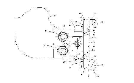
~IG. 1 is an end elevation showing a track clamp
assembly of the invention in engagement with an I-section
track and connected to a track supporting member; and,
FIG. 2 is a side elevation of the track clamp
assembly, taken as indicated by the line ~-2 o~ FIG. 1 in
order to eliminate the traek suppor~ing member from this
view for the sake o~ clarity.
In FIGS. 1 and 2, a track clamp assembly 10 o~
~ the invention is shown in en~agemen~ with a ~rack 12 having
an I-shape~ cross-sectiQnal con~iguration formed by a
vertical web 13 and upper and lower parallel horizontal
f:langes 14 and 15 at the opposite ends o~ the web 13. A
pair of oppositely ~acing upper and lower grooves 16 and 17
extend longi~udinally of the track 12 on eac~l side of the
web 13 at the ~unction between the web 13 and the ~langes
14 and lS. As shown, the grooves 16 and 17 are defined by
portio~s 18 which project from ~he ~langes 14 and 15 in


facing rela~ion to each other and in parallel spaced rela-
tion with the web 13 on eacll side thereof. Tracks having
a cross-sectional configuration o ~his general type are
conventionally employed in monorail systems in which
wheels of a self-propelled vehicle are supported on the
upper flange 14 and guided by the flange portions 18.
The track clamp assembly 10 is composed of an
upper clamp member 20 and a lower clamp member 22 which
are substantially configured correspondingly and opposite-
ly to each other. The upper clamp member has a plate-like
main portion or body 23 de~ined ~y an inner face 24 and an
outer face 25; by parallel, longer and shorter ends 26 and
27 spaced apart a desired distance longi~udinally of the
track 12; by an upper edge 2~ extending linearly between
the upper extremities of ~he ends 26 and 27 perpendicular
thereto; and by ramp sur~aces 30 and 31 disposed between
the lower exre~.lities of ~he ends 26 and 7.7 and offset by
a surface 32 which is parallel to the ends and which forms
part of a tab or bracket 34 projecting from and normal to
the outer face 25. Ramp surfaces 30 and 31 extend
obliquely to the upper edge 28 and are ~ormed as opposite-
ly ~acing V-shaped guldes ~FIG. 1~. The upper edge 2g is
insertable in one of ~he upper grooves 16 of the track 12,
The corresponding, oppositely configured lower
clamp member 22 has a plate-like body 36 with an inner
face 37, an outer face 3~, parallel shorter an~ longer
: ends 39 and 40, a lower edge 42 extending linearly between

2 ~


the lower extremities of the ends, and ramp surfaces 44
and 4$ disposed between upper ex~remities o~ the ends 39
and 40 and offset by a surface 46 forming part of a tab
48 which projects from the outer ~ace 38 and which is
smaller than the bracket 34 o~ the upper clamp member 20.
Ramp surfaces 44 and 45 extend obliquely to the lower edge
42, and are also formed as oppositely facing V-shaped
guides, respectively complementary to the ramp surfaces 30
and 31 of the upper clamp member 20. The lower e~ge 42 is
insertable in one of the lower grooves 17 of the track 12,
which lower groove forms with one of the upper grooves 16
a pair of grooves on one side of the web 13 of the track.
As shown in FIG. 1, the lower edge 42 of the
lower clamp member 22 is a tapered surface inclined upward-
ly toward the outer face 38 of the member 2Z; likewise, the
upper edge 28 o~ the upper clamp member 20 is oppositely
tapered, being inclined downwardly toward the outer face 25
of the member 20. The edges 28 and 42 thus outwardly
converge.
A connecting bolt 50 extends longitudinally or
lengthwise of ~he clamp assembly lQ through holes in the
~ab 48 oE the lower clamp member 22 and in the bracket 34
o.~ the upper clamp member 20 for connecting the clamp
members together in assembled relation engaging the track
12, This connection is made by first positioning the
upper clamp memb~r 20 with its inner ~ace against one side
of the vertical web 13 of the tra~k 12 and with its upper

2 ~


edge 2~ inser~ed in the upper groove 16 of the pair of
grooves on that side of the vertical web 13. The lower
clamp member 22 is positioned to the right of the upper
clamp member (as sho~ in bro~en line in FIG. 23, is
placed with it9 inner face 37 adjacent to the vertical
web 13 of the track 12 and with its lower edge 42 insert-
ed into the lower groove 17 o~ the pair of grooves. Then,
the clamp members 20 and 22 are relati~ely moved toward
each other so that the end 39 and adjacent por~ion of the
outer face 38 of the lower clamp member 22 pass inside of
a notch 5~ (FIG. 1) on the bracket 34 o~ the upper clamp
member 20. Opposed ramp surfaces 30 and 31 on the upper
clamp member 20 and 44 and 4S on the lower clamp member 22
are brought into interenga~ement, the connecting bolt 50
is ins~alled, and a nut 52 is threaded onto the bolt 50.
Tightening of the bolt and nut connection produces endwise
closing relative movement between the clamp members 20 and
22 along their ramp sur~aces 30, 31 and 44, 45. As sho~m
in FIG. 2, these ramp sur~aces are arranged so as not to
unduely restrict such endwise relative movement. The ramp
sur~ace 44 on the lower clamp member has a length less
than that of the upper ramp surface 30 which it engages,
- the ramp surface 44 terminating in a non-oblique surface
extending to the of~set surface 46. Likewise, the upper
ramp surface 31 has a leng~h less than its complementary
lower ramp sur~ace 45 and terminates in a non-oblique
: sur~ace extending to the of~set surface 32. Offset


:. :
'

2 ~


surfaces 32 and 46 are spaced endwise to provide a range of
endwise movement be~ween the clamp members.
l'he endwise closing relative movement of the
clar,lp members 20 and 22 along their ramp surfaces 30, 31
and 44, 45 results in increasing the dimension between
their upper and lower edges 28 and 42 and places these
edges into firm locking engagement with the track to an
extent controllable by the degree to which the bolt and
nut connection 50, 52 is tightened.
Forces on the track 12 resulting from this
engagement are applied closely ad;acent to the root or base
of the web 13, rather than to ~he midpoint of the flanges
14 and 15, due to the ou~ward convergence of the edges 28
and 42 o~ the clamp members. The engagement so obtained
between the clamp assembly lO and the track 12 is sufficient-
ly positive as to enable the clamp assembly to be employed
as a splîce or connection between adjacent end-to-end sec-
tions of the track 12.
Pairs of holes 54 in the upper clamp member 20
and 55 in the lower clamp member 22 permit the optional
bolting of the assembly 10 to the track 12 by drilling
corresponding holes in the ~ack web 13 after the assembly
lO has bcen installed as described above.
FIG. l illustrates in broken line a track support-
ing member 56 and means comprising a pair o~ bolts 58 for
attaclling the bracke~ 3~ o~ ~he upper clamp member 20 of the
clamp asser.lbly 10 to the track supporting member. This


a~tachment of the upper clamp member 20 to the track
supporting member 56 can be made prior to the installation
of the ~rack 12. When a series of upper clamp members 20
have been so a~tached to a series of track supporting
members, a section o~ the track 12 can be hung on the upper
clamp members 20 and positioned thereby at proper elevation
while a lower clamp rnember 2~ .is installed on each of the
series of upper clamp members. The track supporting member
56 can be simply formed from plate stock and can be attach
ed to either side of the upper clamp member bracket 34.
The lower terminal end 60 of the supporting member 56 is
provided with a recess 62 for clearance in the installation
of the connecting bolt 50 and nut 52.
The clamp assembly 10 thus has the advantages of
minimal assembly time; of providing an accurate support for
the track 12 during the installation thereof; of providing
a positive locking engagement with the track member that
compensates for dimensional tolerances and that applies
forces to the track member adjacent to its vertical web;
and, of main~aining alignment between the upper and lower
clamp members 20 and 22 both during and after their assembly
by the interengagement of their opposing, V-shaped guides
o~ the ramp surfaces 30, 31 and 44, 45.

Dessin représentatif
Une figure unique qui représente un dessin illustrant l'invention.
États administratifs

Pour une meilleure compréhension de l'état de la demande ou brevet qui figure sur cette page, la rubrique Mise en garde , et les descriptions de Brevet , États administratifs , Taxes périodiques et Historique des paiements devraient être consultées.

États administratifs

Titre Date
Date de délivrance prévu 1999-03-30
(22) Dépôt 1990-02-28
(41) Mise à la disponibilité du public 1990-09-06
Requête d'examen 1993-11-24
(45) Délivré 1999-03-30
Réputé périmé 2002-02-28

Historique d'abandonnement

Il n'y a pas d'historique d'abandonnement

Historique des paiements

Type de taxes Anniversaire Échéance Montant payé Date payée
Le dépôt d'une demande de brevet 0,00 $ 1990-02-28
Enregistrement de documents 0,00 $ 1990-08-31
Taxe de maintien en état - Demande - nouvelle loi 2 1992-02-28 100,00 $ 1991-03-06
Taxe de maintien en état - Demande - nouvelle loi 3 1993-03-01 100,00 $ 1993-01-06
Taxe de maintien en état - Demande - nouvelle loi 4 1994-02-28 100,00 $ 1993-11-24
Taxe de maintien en état - Demande - nouvelle loi 5 1995-02-28 150,00 $ 1995-01-18
Taxe de maintien en état - Demande - nouvelle loi 6 1996-02-28 150,00 $ 1995-12-20
Taxe de maintien en état - Demande - nouvelle loi 7 1997-02-28 150,00 $ 1997-01-02
Taxe de maintien en état - Demande - nouvelle loi 8 1998-03-02 150,00 $ 1997-12-23
Taxe finale 300,00 $ 1998-12-15
Taxe de maintien en état - Demande - nouvelle loi 9 1999-03-01 150,00 $ 1999-01-04
Taxe de maintien en état - brevet - nouvelle loi 10 2000-02-28 200,00 $ 2000-01-11
Titulaires au dossier

Les titulaires actuels et antérieures au dossier sont affichés en ordre alphabétique.

Titulaires actuels au dossier
JERVIS B. WEBB COMPANY
Titulaires antérieures au dossier
DUCZKOWSKI, EDWARD M. JR.
MCDONALD, CLAYTON C.
Les propriétaires antérieurs qui ne figurent pas dans la liste des « Propriétaires au dossier » apparaîtront dans d'autres documents au dossier.
Documents

Pour visionner les fichiers sélectionnés, entrer le code reCAPTCHA :


Pour visualiser une image, cliquer sur un lien dans la colonne description du document. Pour télécharger l'image (les images), cliquer l'une ou plusieurs cases à cocher dans la première colonne et ensuite cliquer sur le bouton "Télécharger sélection en format PDF (archive Zip)" ou le bouton "Télécharger sélection (en un fichier PDF fusionné)".

Liste des documents de brevet publiés et non publiés sur la BDBC .

Si vous avez des difficultés à accéder au contenu, veuillez communiquer avec le Centre de services à la clientèle au 1-866-997-1936, ou envoyer un courriel au Centre de service à la clientèle de l'OPIC.


Description du
Document 
Date
(yyyy-mm-dd) 
Nombre de pages   Taille de l'image (Ko) 
Dessins représentatifs 1999-03-26 1 9
Page couverture 1999-03-26 1 54
Page couverture 1993-12-11 1 16
Abrégé 1993-12-11 1 26
Revendications 1993-12-11 3 117
Dessins 1993-12-11 1 39
Description 1993-12-11 8 352
Revendications 1998-07-21 3 101
Correspondance 1998-12-15 1 35
Taxes 1999-01-04 1 32
Taxes 1997-12-23 1 32
Lettre du bureau 1994-02-07 1 72
Correspondance de la poursuite 1993-11-24 2 41
Correspondance de la poursuite 1998-06-03 2 36
Correspondance de la poursuite 1998-02-06 2 40
Correspondance de la poursuite 1994-08-26 1 25
Taxes 1997-01-02 1 22
Taxes 1995-12-20 1 22
Taxes 1995-01-18 1 28
Taxes 1993-11-24 1 23
Taxes 1993-01-06 1 21
Taxes 1991-03-06 1 23