Sélection de la langue

Search

Sommaire du brevet 2011319 

Énoncé de désistement de responsabilité concernant l'information provenant de tiers

Une partie des informations de ce site Web a été fournie par des sources externes. Le gouvernement du Canada n'assume aucune responsabilité concernant la précision, l'actualité ou la fiabilité des informations fournies par les sources externes. Les utilisateurs qui désirent employer cette information devraient consulter directement la source des informations. Le contenu fourni par les sources externes n'est pas assujetti aux exigences sur les langues officielles, la protection des renseignements personnels et l'accessibilité.

Disponibilité de l'Abrégé et des Revendications

L'apparition de différences dans le texte et l'image des Revendications et de l'Abrégé dépend du moment auquel le document est publié. Les textes des Revendications et de l'Abrégé sont affichés :

  • lorsque la demande peut être examinée par le public;
  • lorsque le brevet est émis (délivrance).
(12) Brevet: (11) CA 2011319
(54) Titre français: CONTENANT D'EMBALLAGE POUR LIQUIDE, SURTOUT SOUS PRESSION
(54) Titre anglais: PACKING CONTAINER FOR LIQUID, ESPECIALLY PRESSURIZED CONTENTS
Statut: Périmé et au-delà du délai pour l’annulation
Données bibliographiques
(51) Classification internationale des brevets (CIB):
  • B65D 53/08 (2006.01)
  • B65D 17/50 (2006.01)
(72) Inventeurs :
  • BJORCK, BENGT (Suède)
(73) Titulaires :
  • TETRA LAVAL HOLDINGS & FINANCE S.A.
(71) Demandeurs :
  • TETRA LAVAL HOLDINGS & FINANCE S.A. (Suisse)
(74) Agent: MARKS & CLERK
(74) Co-agent:
(45) Délivré: 1998-09-15
(22) Date de dépôt: 1990-03-02
(41) Mise à la disponibilité du public: 1990-09-29
Requête d'examen: 1992-05-19
Licence disponible: S.O.
Cédé au domaine public: S.O.
(25) Langue des documents déposés: Anglais

Traité de coopération en matière de brevets (PCT): Non

(30) Données de priorité de la demande:
Numéro de la demande Pays / territoire Date
8901092-0 (Suède) 1989-03-29

Abrégés

Abrégé français

Récipient d'emballage comportant une paroi d'extrémité (3) et une ouverture de vidage (4) incorporée dans la paroi d'extrémité, laquelle est recouverte d'une bande de fermeture (5) appliquée de façon détachable à l'extérieur de la paroi d'extrémité. La bande de fermeture (5) et la paroi d'extrémité (3) sont faites de métal recouvert de plastique et sont rattachées l'une à l'autre le long d'un joint de scellement formé par fusion superficielle sur tout le pourtour de l'ouverture de vidage.


Abrégé anglais


A packing container comprising an end wall (3) and an
emptying opening (4) incorporated in the end wall which is
covered by means of a cover strip (5) applied detachably to
the outside of the end wall. The cover strip (5) as well
as the end wall (3) consist of a plastic-coated metallic
material and are attached to one another along a sealing
joint formed by surface fusion around the whole emptying
opening .

Revendications

Note : Les revendications sont présentées dans la langue officielle dans laquelle elles ont été soumises.


THE EMBODIMENTS OF THE INVENTION IN WHICH AN EXCLUSIVE
PROPERTY OR PRIVILEGE IS CLAIMED ARE DEFINED AS FOLLOWS:-
1. A container having an interior for holding contents,
comprising: a body, an end wall located at one end of the
body, an opening formed in the end wall for emptying the
contents of the container, and an outer cover strip covering
the opening, said end wall being formed of a metal layer and
a coating of weldable plastic material, said metal layer of
said end wall having an inwardly facing surface which faces
towards the interior of the container and an oppositely
positioned outwardly facing surface, said opening being
defined by a peripheral wall extending between the inwardly
and outwardly facing surfaces of the metal layer, said
coating of weldable plastic material being disposed on and
in contact with at least the outwardly facing surface of the
metal layer of the end wall, said coating of weldable
plastic material also being disposed on and in contact with
substantially the entire peripheral wall that defines the
opening in the end wall, said cover strip being formed of a
metal layer which has a coating of weldable plastic material
disposed on at least one side thereof, said coating of
plastic material on the at least one side of the cover strip
being in contact with and sealed to the coating of plastic
material disposed on the outwardly facing surface of the
metal layer of the end wall along a liquid-tight sealing
joint that surrounds the opening, said cover strip including
a mounting part and a gripping part, said mounting part
having an outermost peripheral edge, and wherein the
outermost peripheral edge of the mounting part of the cover
strip is sealed to the end wall.
2. The container according to claim 1, wherein the metal
layer in the end wall is formed at least partially of iron.

3. The container according to claim 1, wherein the metal
layer in the cover strip is formed at least partially of
iron.
4. The container according to claim 1, wherein the weldable
plastic material on the cover strip and the end wall is a
polyester material.
5. The container according to claim 4, wherein said
polyester material is polyethylene terephthalate.
6. The container according to claim 1, wherein said end wall
has an edge portion integrally formed therewith and
extending therefrom, said edge portion being secured to the
body.
7. The container according to claim 6, wherein said body
tapers towards the end wall, said edge portion of the end
wall being secured to an inner surface of the tapering body
for securing the end wall to the body.
8. The container according to claim 1, wherein said cover
strip includes a mounting part and a gripping part formed
integrally with and extending from the mounting part, said
mounting part being secured to the end wall and covering the
opening.
9. The container according to claim 1, wherein said body is
formed of a metal layer and a coating of plastic material
that faces the interior of the container, said end wall
having an edge portion that is surface fused to said coating
of plastic material on the body.
10. The container according to claim 9, wherein the coatings
of plastic material forming a part of the body, the end
wall, and the cover strip are polyester material.
11. The container according to claim 10, wherein the
coatings of plastic material forming a part of the body, the
end wall, and the cover strip are polyethylene
terephthalate.

12. The apparatus according to claim 1, wherein said cover
strip includes a mounting part and a gripping part, the
thickness of the coatings of plastic material positioned
between the metal layer of the end wall and the metal layer
of the mounting part after the coatings of plastic material
have been sealed to one another is substantially constant
over the entire area of the mounting member.
13. The container according to claim 1, wherein said end
wall includes an end wall portion and an edge portion
extending from the end wall portion, said body including a
side wall having an inner surface, said opening for emptying
the contents of the container being formed in the end wall
portion, said edge portion extending downwardly from said
end wall portion and terminating in a free end so that said
end wall portion and said edge portion together define a
truncated coneshaped member, and wherein an outer peripheral
surface of said edge portion is sealed to the inner surface
of the side wall of the body, said free end of the edge
portion being coated with plastic material, said end wall
portion being positioned above the free end of the edge
portion.
14. The container according to claim 1, wherein said body
includes a side wall, said outer cover strip being
positioned above said side wall of said body.
15. A container for holding pourable contents comprising: a
hollow body having a side wall and an open end; an end wall
member mounted in said open end, said end wall member having
a substantially flat end wall portion and an edge portion
integrally formed therewith, said edge portion being sealed
in a liquid-tight manner to an inner surface of said side
wall adjacent said open end; a pouring opening formed in the
end wall portion for pouring the contents out of the hollow
body, said pouring opening being defined by a peripheral
wall; and a cover strip covering the pouring opening, said
cover strip including a mounting part and a gripping part

integrally formed with and extending away from the mounting
part, said mounting part having an outermost peripheral
edge, said mounting part and said end wall member being
formed of a central metal layer coated on both sides with a
coating of plastic material, the coating of plastic material
on one side of the central metal layer of the mounting part
facing and being sealed through surface fusion to the
coating of plastic material on one side of the central metal
layer of the end wall member along a liquid-tight sealing
joint that surrounds the pouring opening, the coating of
plastic material on the end wall member being disposed on
and in contact with substantially the entire peripheral wall
that defines the pouring opening in the end wall portion,
the thickness of the coatings of plastic material positioned
between the metal layer of the end wall member and the metal
layer of the mounting part after the coatings of plastic
material have been sealed to one another being substantially
constant over the entire area of the mounting part.
16. The container according to claim 15, wherein said edge
portion extends downwardly from said end wall portion and
terminates in a free end so that said end wall portion and
said edge portion together define a truncated cone-shaped
member, and wherein an outer peripheral surface of said edge
portion is sealed to the inner surface of the side wall of
the body, said free end of the edge portion being coated
with plastic material, said end wall portion being
positioned above the free end of the edge portion.
17. The container according to claim 15, wherein said body
is formed of a metal layer and a coating of plastic material
which faces towards an interior of the container.
18. The container according to claim 17, wherein the
coatings of plastic material forming a part of the body, the
end wall member, and the cover strip are polyester material.
19. The container according to claim 18, wherein the
coatings of plastic material forming a part of the body, the

end wall member, and the cover strip are polyethylene
terephthalate.
20. The apparatus according to claim 15, wherein outermost
portions of the mounting part of the cover strip adjacent
the periphery are sealed to the end wall member.
21. The container according to claim 15, wherein said cover
strip is positioned above said side wall of said body.
22. A method of forming an opening arrangement on a
container, comprising the steps of: forming a container
having an end wall located at one end thereof, said end wall
including a metal layer, forming an opening in the end wall
so that said opening is defined by an inner peripheral wall
that extends between upper and lower surfaces of said end
wall, applying a coating of weldable plastic material to the
metal layer of the end wall so that the coating of weldable
plastic material is in contact with the metal layer on at
least one side of the metal layer and so that the coating of
weldable plastic material covers substantially the entire
inner peripheral wall of the opening; providing a cover
strip formed of a metal layer and a coating of weldable
plastic material in contact with the metal layer on at least
one side of the metal layer; and sealing the cover strip to
the end wall by sealing the coating of weldable plastic
material of the cover strip directly to and in contact with
the coating of weldable plastic material of the end wall,
and cover strip being sealed to the end wall such that the
cover strip covers the opening in the end wall.
23. The method according to claim 22, wherein said container
is formed with a hollow body having a side wall that is
shaped to define an interior and to form an opening, said
side wall of said hollow body being made of a metal layer

and a coating of plastic material on at least a side of the
metal layer that faces the interior of the body; said end
wall including an end wall member having a substantially
flat end wall portion and an edge portion integrally formed
therewith and extending therefrom, said edge portion being
formed of a metal layer having an outwardly facing surface
and a coating of plastic material entirely covering the
outwardly facing surface of the metal layer; and sealing
said coating of plastic material on the side wall of the
body to said coating of plastic material on the edge portion
of the end wall member so that the end wall portion of the
end wall member defines the end wall of the container.
24. The method according to claim 22, wherein said coating
of weldable plastic material on the cover strip is sealed to
said coating of weldable plastic material on the end wall
through induction heating.
25. The method according to claim 22, wherein said cover
strip includes a mounting part and a gripping part, said
mounting part having outermost portions adjacent the
periphery and wherein said step of sealing the cover strip
to the end wall includes sealing said outermost portions of
the mounting part to the end wall.
26. Packaging container comprising a container body, at
least one end wall, an emptying opening in said end wall,
and an outer cover strip applied over said emptying opening
to the outside of said end wall, wherein said cover strip as
well as said end wall consist of a material comprising a
metal layer and at least one outer coating of weldable
plastic material and wherein said cover strip is connected
to said end wall along a sealing joint around the whole
emptying opening which is liquid-tight but can be broken up,
formed by surface fusion of plastic material, characterized

in that said end wall comprises a downwardly directed edge
portion which serves as a fastening means and which is at
least partially inserted into its outer plastic coating and
which is liquid-tightly and mechanically durably sealed to
the inside of an upwardly tapering container body and that
said sealing joint around said emptying opening is formed by
the outer plastic coating of said cover strip and of said
end wall.
27. Packing container as claimed in claim 26, characterized
in that said edge portion is sealed to the inside of the
upper open end of a conical container body.

Description

Note : Les descriptions sont présentées dans la langue officielle dans laquelle elles ont été soumises.

CA 02011319 1998-04-09
A PACKING CONTAINER FOR LIQUID, ESPECIALLY PRESSURIZED
CONTENTS
The present invention relates to a packing container
of non-returnable character for liquid, especially
pressurized, contents, which comprises at least one plane
end wall, an emptying opening incorporated in the end wall
and an outer cover strip which is applied over the emptying
opening to the outside of the end wall.
In packing technology frequently non-returnable
packages of a can character are used for the packaging of
liquid, especially pressurized, contents such as beer,
refreshing beverages and similar carbonated products.
These known can packages generally consist of a cylindrical
can body provided with a base, the upper end of the can
body being closed with the help of a, substantially, plane
end wall which is seamed onto the cylindrical can body.
The cylindrical can body generally consists of plastic or
metal, e.g. iron or aluminum, whereas the plane end wall as
a rule always consists of sheet aluminum.
To make the package conveniently openable it is
provided in most cases with some type of opening
arrangement which on the one hand should make the package
readily openable and on the other hand should allow a
smooth emptying of the contents from the opened package.
A very usual opening arrangement on such known can
packages has a weakened or openable part in the plane end
wall which by means of a pull-ring fixed to the weakened or
openable part is adapted so that it can be completely
pulled off to expose an emptying opening through which the
contents of the package can be made accessible. One
problem, not infrequently encountered in this,
intrinsically simple and in most cases well-functioning,
opening arrangement is that the openable end wall has to be
manufactured from a relatively soft material, preferably
aluminum, which is both soft and easy to process, but which

CA 02011319 1998-04-09
from a point of view of manufacture is a very energy-
consuming and thus cost-demanding metal. For the sake of
making the package more economical, therefore, it is
necessary, among other things, to recover and reuse as much
as possible of the aluminum content of the package used,
which, however, is counteracted or seriously obstructed by
the fact that the part of the end wall of the package
pulled off on opening of the package, including the pull-
ring, in most cases is thrown away and thus is completely
lost after a single use. To the economic loss also comes
that the wasted portion of the end wall represents a
substantial environmental problem, since it can remain
lying about in nature for a very long time before it breaks
down through corrosion, and constitutes during this time,
because of its sharp edges, a hazard to humans and animals.
Another opening arrangement on known can packages of
the type which has been described above consists of an
emptying opening incorporated in the end wall of the drum
which is covered by a cover strip or similar closure device
slued detachably onto the outside of the end wall. This
known opening arrangement too is relatively simple and easy
to manufacture and as a rule functions well, but it has the
disadvantage, among other things, especially in the case of
can packages for pressurized contents, that it requires
environmentally doubtful and expensive glue to provide the
joint between cover strip and package end wall with the
required tightness and durability.
The abovementioned inconveniences are avoided in
accordance with the present invention in that a packing
container of the type described in the introduction has
been given the characteristic that the cover strip as well
as the said end wall are made of a material comprising a
layer of metal and at least one outer coating of weldable
plastics and that the cover strip is connected to the end
wall along a sealing joint around the whole emptying

CA 02011319 1998-04-09
opening which is liquid-tight, but can be broken up, formed
by surface fusion of plastic coatings facing one another on
the cover strip and the end wall respectively.
In accordance with a particularly preferred embodiment
of the invention the sealing joint between the cover strip
and the end wall of the package is produced by inductive
heating in a manner known in itself of the metal layers
incorporated in the cover strip and the end wall
respectively, which has been found to bring about that the
package can be closed in a rapid and simple manner and that
the actual closing process can be easily monitored both
with regard to heating period and temperature and that the
sealing joint will be tighter and more durable than, for
example, in the case of glueing.
Further preferred embodiments and advantages of the
invention have been given, moreover, the characteristics
specified in the following subsidiary claims.
The invention will now be described in greater detail
with special reference to the attached drawing, wherein
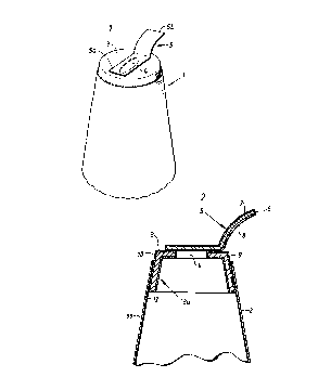
Figure 1 shows schematically the top part of a packing
container provided with an opening arrangement in
accordance with the invention, and
Figure 2 shows a central section of the container
according to Figure 1.
Although the invention can be applied to all packages
of a can character, it is assumed in the special embodiment
referred to here that the package, which has been given the
general reference designation 1, is of the type which is
shown in Figure 1 and which consists of an upwards tapering
can body 2 provided with any kind of bottom closure and a
substantially plane end wall 3 arranged at the upper open
end of the can body. The end wall 3 has an emptying
opening 4 incorporated beforehand which is covered on the
top by means of an outer cover strip 5 applied to the
outside of the end wall. The cover strip 5 comprises on

CA 02011319 1998-04-09
the one hand a mounting part 5a, which is connected
detachably to the end wall 3 over the emptying opening 4,
and on the other hand a readily accessible gripping part 5b
by means of which the cover strip 5 is adapted to be
removed on opening of the package.
As is evident more clearly from Figure 2, the cover
strip 5 is manufactured from a laminated material
comprising a central layer of material strong in tension,
e.g. iron, and outer coatings 7 and 8 of weldable plastic,
e.g. polyester (preferably polyethylene terephthalate).
Figure 2 further illustrates that the end wall 3 too is
manufactured from a material comprising a central metallic
layer 9 with an outer (plastic) coating 10 of weldable
plastics, e.g. polyester (preferably polyethylene
terephthalate). The end wall 3 has a downwards directed
edge portion 3a serving as a fastening means which extends
unbroken around the whole periphery of the end wall and
which, at least partially, is inserted in, and is fastened
to, the inside of the can body 2 along a liquid-tight and
mechanically durable sealing joint around the whole thus
inserted part of the edge portion 3a of the end wall.
As pointed out earlier, it is important that the joint
between the outer cover strip 5 and the end wall 3, on the
one side, should be sufficiently strong to be able to
withstand the internal pressure of the package, which in
the case of contents such as beer, refreshing beverages and
similar carbonated drinks may go up to approx. 7 bar, but
that the joint, on the other side, should not be so strong
that, on opening of the package, an intentional pulling off
of the cover strip is made impossible or is made
unnecessarily difficult. In accordance with the invention
a desirable optimum joint is obtained in that the cover
strip S and the end wall 3 are connected with one another
along a sealing joint formed by surface fusion between the
plastic coatings 8 and 10 respectively facing one another,

CA 02011319 1998-04-09
and it has been found ln particular that a sealing joint
which functions well and is easily controllable can be
obtained if the cover strip 5 and the end wall 3 are joined
to one another by inductive heating of metal layers 6 and 9
incorporated in the cover strip 5 and the end wall 3
respectively. Such an inductive heat sealing is both rapid
and simple and can be carried out with the help of existing
conventional equipment. The method, among other things,
has the further advantage that it can be easily monitored
both with regard to heating period and to temperature, so
that a mechanically durable sealing joint which is liquid-
tight but easily breakable is obtained around the whole
emptying opening 4.
The can body 2, which preferably is of the conical
shape indicated in Figures 1 and 2, is also manufactured
appropriately from a material comprising a thin inner metal
layer 11 and at least one outer coating 12 of weldable
plastic, preferably polyethylene terephthalate, facing
towards the inside of the package, as a result of which the
joint between the inserted part of the edge portion 3a of
the end wall 3 and the inner plastic coating 12 of the
container body 2 can also be achieved by inductive heating
in a manner known in itself.
The example of an embodiment of the invention
described here is intended solely to illustrate a
particularly suitable embodiment, and it is possible, of
course, within the scope of the concept of the invention to
realize a number of modifications, both with regard to the
composition, and to the general design, of the packing
container without departing, for this reason from the
actual idea of the invention.

Dessin représentatif
Une figure unique qui représente un dessin illustrant l'invention.
États administratifs

2024-08-01 : Dans le cadre de la transition vers les Brevets de nouvelle génération (BNG), la base de données sur les brevets canadiens (BDBC) contient désormais un Historique d'événement plus détaillé, qui reproduit le Journal des événements de notre nouvelle solution interne.

Veuillez noter que les événements débutant par « Inactive : » se réfèrent à des événements qui ne sont plus utilisés dans notre nouvelle solution interne.

Pour une meilleure compréhension de l'état de la demande ou brevet qui figure sur cette page, la rubrique Mise en garde , et les descriptions de Brevet , Historique d'événement , Taxes périodiques et Historique des paiements devraient être consultées.

Historique d'événement

Description Date
Inactive : CIB de MCD 2006-03-11
Le délai pour l'annulation est expiré 2004-03-02
Lettre envoyée 2003-03-03
Accordé par délivrance 1998-09-15
Inactive : Taxe finale reçue 1998-04-09
Préoctroi 1998-04-09
Inactive : Pages reçues à l'acceptation 1998-04-09
Un avis d'acceptation est envoyé 1997-10-22
Lettre envoyée 1997-10-22
Inactive : Renseign. sur l'état - Complets dès date d'ent. journ. 1997-10-15
Inactive : Dem. traitée sur TS dès date d'ent. journal 1997-10-15
Inactive : CIB enlevée 1997-08-27
Inactive : CIB en 1re position 1997-08-27
Inactive : CIB attribuée 1997-08-27
Inactive : Approuvée aux fins d'acceptation (AFA) 1997-08-13
Exigences pour une requête d'examen - jugée conforme 1992-05-19
Toutes les exigences pour l'examen - jugée conforme 1992-05-19
Demande publiée (accessible au public) 1990-09-29

Historique d'abandonnement

Il n'y a pas d'historique d'abandonnement

Taxes périodiques

Le dernier paiement a été reçu le 1998-02-17

Avis : Si le paiement en totalité n'a pas été reçu au plus tard à la date indiquée, une taxe supplémentaire peut être imposée, soit une des taxes suivantes :

  • taxe de rétablissement ;
  • taxe pour paiement en souffrance ; ou
  • taxe additionnelle pour le renversement d'une péremption réputée.

Veuillez vous référer à la page web des taxes sur les brevets de l'OPIC pour voir tous les montants actuels des taxes.

Historique des taxes

Type de taxes Anniversaire Échéance Date payée
TM (demande, 8e anniv.) - générale 08 1998-03-02 1998-02-17
Taxe finale - générale 1998-04-09
TM (brevet, 9e anniv.) - générale 1999-03-02 1999-02-19
TM (brevet, 10e anniv.) - générale 2000-03-02 2000-02-18
TM (brevet, 11e anniv.) - générale 2001-03-02 2001-02-20
TM (brevet, 12e anniv.) - générale 2002-03-04 2002-02-21
Titulaires au dossier

Les titulaires actuels et antérieures au dossier sont affichés en ordre alphabétique.

Titulaires actuels au dossier
TETRA LAVAL HOLDINGS & FINANCE S.A.
Titulaires antérieures au dossier
BENGT BJORCK
Les propriétaires antérieurs qui ne figurent pas dans la liste des « Propriétaires au dossier » apparaîtront dans d'autres documents au dossier.
Documents

Pour visionner les fichiers sélectionnés, entrer le code reCAPTCHA :


Pour visualiser une image, cliquer sur un lien dans la colonne description du document. Pour télécharger l'image (les images), cliquer l'une ou plusieurs cases à cocher dans la première colonne et ensuite cliquer sur le bouton "Télécharger sélection en format PDF (archive Zip)" ou le bouton "Télécharger sélection (en un fichier PDF fusionné)".

Liste des documents de brevet publiés et non publiés sur la BDBC .

Si vous avez des difficultés à accéder au contenu, veuillez communiquer avec le Centre de services à la clientèle au 1-866-997-1936, ou envoyer un courriel au Centre de service à la clientèle de l'OPIC.


Description du
Document 
Date
(aaaa-mm-jj) 
Nombre de pages   Taille de l'image (Ko) 
Description 1994-03-01 5 167
Abrégé 1994-03-01 1 11
Revendications 1994-03-01 2 37
Page couverture 1994-03-01 1 12
Dessins 1994-03-01 1 10
Page couverture 1993-10-15 1 12
Revendications 1993-10-15 2 37
Abrégé 1993-10-15 1 11
Dessins 1993-10-15 1 10
Description 1993-10-15 5 167
Description 1998-04-09 5 241
Abrégé 1998-04-09 1 12
Dessin représentatif 1998-08-21 1 6
Page couverture 1998-08-21 1 37
Description 1997-07-16 5 212
Revendications 1997-07-16 7 315
Avis du commissaire - Demande jugée acceptable 1997-10-22 1 165
Avis concernant la taxe de maintien 2003-03-31 1 174
Correspondance 1998-04-09 7 289
Correspondance 1997-10-22 1 98
Taxes 1997-02-13 1 73
Taxes 1995-02-10 1 56
Taxes 1996-02-06 1 56
Taxes 1994-02-15 1 55
Taxes 1992-12-01 1 35
Taxes 1992-01-07 1 29
Demande de l'examinateur 1995-09-01 2 95
Courtoisie - Lettre du bureau 1992-06-12 1 38
Correspondance de la poursuite 1996-02-29 3 108
Correspondance de la poursuite 1992-05-19 1 28