Note : Les descriptions sont présentées dans la langue officielle dans laquelle elles ont été soumises.
2~1225~
This invention relates to containers and more
particularly to re-usable, collapsible containers.
Applicant is awar~ of the known permanently assembled
wooden crates which are used f~r holding industrial
articles such as machinery, while transporting them
from a source to a destination. These crates are not
collapsible nor adjustable in size and furthermore,
they normal~y are used only once, after which they are
destroyed.
lo It is an object of the present invention to provide an
alternative container with which the applicant believes
the aforementioned disadvantages will at least be
alleviated. It is a further object of the invention to
provide a container with exceptional rigidity and
strength characteristics.
According to the invention a collapsible container
comprises:
- a base;
- a plurality of w~lls t each having a width and a
- 2 - ~
height dimension; 2~
- the walls being erectable on the base to rise
therefrom;
- each wall comprising at least two wall members
slidingly connected to one another so that the
members may slidingly be manipulated to adjust the
height of the wall; and
- a lid mountable on the walls to close the
container.
Thus, with the apparatus according to the in~ention a
container, the height of which is adjustable, may be
formed. After use of the container, it is knocked down
again so that it may be transported back to the source,
re-assembled and used again.
It will be appreciated that in its collapsed form, with
the walls lying flat between the base and lid, the
container takes up much less space than in its
assembled form. Typical apparatus according to the
invention may be used to assemble a container with a
length of 2250mm, a width of 1930mm and a height
20~50
adjustable between 1200 and 2000mm. It has been found
that in their collapsed form approximately seventy of
these containers fit into a single twelve meter ship
container.
The base is prefe{ably rectangular and two end walls
are hinged to two opposed ends of the base so that they
are movable between a first position wherein they lie
substantially flat on the base and a second position
wherein they rise from the base.
Also in the preferred embodiment, two separate side
walls are mountable on the base between the end walls.
The base preferably comprises a pallet.
Each wall comprises two rectangular wall members, each
wall member including a frame comprising a plurality of
spaced posts cladded with a sheet, the posts of the one
member being telescopically movable in the
corresponding posts of the other member so that the
members may slidingly be manipulated relative to one
another to adjust the height of the wall.
2012250
The posts may define spaced apertures and the two
members may be locked in a desired position relative to
one another by means of locking means extending through
registering apertures in the telescopic posts.
The lid is securable to the side walls by means of nuts
and bolts.
In the collapsed condition the end walls are folded
down onto the base to lie adjacent one another, the
side walls are located on the end walls and the lid is
located on the side walls and secured to the base by
means of a formation extending between the lid and the
base.
The ~ormation preferably comprises a pillar securable
to the base by means of the nuts and bolts for mounting
the side walls on the base in the assembled condition
and to the lid by the nuts and bolts for mounting the
lid on the side walls in the assembled condition.
The invention will now further be described, by way of
- 20~22S~
example only, with reference to the accompanying
diagrams wherein:
figure 1 : is a diagrammatic perspective view,
partially broken away, of a collapsible
container according to the invention in its
^ assemb~ed condition;
figure 2 : is a diagrammatic perspective view of the
container according to the invention
showing only the base and two walls that
are adjustable in height;
figure 3a: is a diagrammatic side view of the
collapsible container according to the
invention in its collapsed or knocked down
condition;
figure 3b: is a diagrammatic enlarged and broken away
view of the container according to the
invention in its collapsed or knocked down
condition;
figure 4 : is a plan view of the base of the container
according to the invention;
figure 5a: is a diagrammatic broken away sectional
view of an end wall of the container hinged
;~01225()
to the base and in an upright position;
'igure 5b: is a view similar to figure 5a, but with
the end wall in a folded down position;
'igure 6 : is a diagrammatic, broken away sectional
5view of a separate side wall mounted on the
base to rise therefrom;
'igure 7a: is a diagrammatic broken away sectional
view of a lid of the container mounted on a
side wall;
ln'igure 7b: is a view similar to that in figure 7a, but
of part of the lid only, showing a seal
on the lid;
figure 8 : is a sectional, broken-away view in plan of
a corner region where a side wall and an
15end wall meet in the container's assembled
condition; and
~igure 9 : is a diagrammatic perspective view of two
wall members slidably connected to one
another so that the height of the wall and
2~of the container in its assembled condition
may be adjusted.
201~Z50
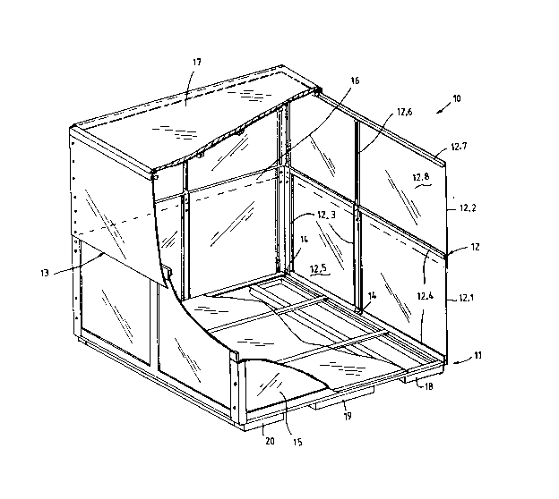
A collapsible container .10 according to the invention
is shown in its assembled condition, in figure 1 and in
its folded down or knoc~ed down condition, in figure 3.
Referring firstly to figure 1, the container 10
comprises a rectangular base 11 in the form of a
pallet, two opposed end walls 12, 13 mounted on base 11
by hinges 14, two separate side walls 15 and 16
removably mountable on base 11 and a lid 17 removably
mountable on upstanding walls 12, 13, 15 and 16.
Walls 12, 13, 15 and 16 are substantially similar in
configuration. Each wall comprises two rectangular
planar members, which are designated by reference
numerals 12.1 and ~2.2, respectively in the case of
wall 12. The members are slidably connected to one
another and manipulatable between a first configuration
(see wall 13 in figure 2) wherein the planar surface of
the members face one another and one or more extended
positions (see wall 12 in both figures 1 and 2) wherein
the two members are located in partially overlapping or
2~ juxtaposition relative to one another.
2()12250
As shown in figure 4 the base 11 comprises three
rectangular formations 18 to 20, each made of
rectanguiar tubing. As shown with reference to
formation 20, each formation is made of two longer
tubing members 2~.t and 20.2 and two shorter members
20.3 and 20.4. A steel sheet 21 is rivetted to these
formations to provide a floor for the container 10.
As shown in figures 1, 5a and 5b, walls 12 and 13 are
mounted on base 11 by means of hinges 14. A first
1~ elongate right angled steel member 22 is welded to tube
member 20.1 of base 11 and a support for the end wall
in the form of an elongate square tube 23 is welded on
the transversely, outwardly extending leg 22.1 of right
angled member 22. A flat bar 24 is welded to the
lS square member 23 to extend downwardly beyond the
transversely extending leg 22.1 of right angled member
22 thereby defining an inverted channel 24.1 wherein a
sling (not shown) of a crane (also not shown) may be
received.
X012250
A second right angled member 25 is welded in partially
overlapping relationship to the first right angled
member 22, so that one of its legs extends upwardly,
away from member 20.1. As shown in figures 5a, b and 9
one limb of hinge 14 is welded to this upstanding leg,
while t~e ~ther is welded to a spacer 26 on a post 12.3
of bottom ~ember 12.1 of end wall 12. This
configuration yields a container of exceptional
rigidity and strength.
As shown in figures 5a and 5b end wall 12 is moveable
between a first position (shown in figure 5a) wherein
it rises from base 11 and a second position ~shown in
figure 5b1 wherein it is folded down onto base 11. End
wall 13 is similarly movable between a first position
and a second position.
As shown in figure 6, side wall 15, which is a separate
removable wall, is mounted on base 11 to rise therefrom
when the container is in its assembled condition. On
rectangular member 20.4 of formation 20 of base 11
there is welded an elongate square tube 27. A right
-- 1 0--
20122S0
angled member 28 is welded on member 20.4 with one of
its legs extending upwardly away from member 20.4.
Bottom member 15.1 of side wall 15 is secured to this
leg of member 28 by means of nut and bolt 29. Side
wall 16 is similarly mountable on base 11 on the
opposite side thereof.
Though not clearly shown in the diagrams, square
members 23 in figures 5a and 5b and 27 in figure 6 and
their corresponding members along the opposite end and
side of the base, form a continuous rectangular
formation. Similarly, right angled members 25 and 28
and their corresponding members also extend about the
whole periphery of base 11.
The end and side walls 12, 13, 15 and 16 are similar in
configuration and only end wall 12 will thus be
described in more detail. As best shown in figures 1,
2 and 9, end wall 12 comprises two members, a first
member 12.1 hinged to base 11 and a second member 12.2
slidably mounted on first member 12.1. First wall
member 12.1 comprises a frame including three parallel,
Z~1;~50
top hat-shaped posts 12.3 (only two of which are shown
in figures 1 and 2) and two parallel bars 12.4
extending between the ends of these posts. A steel
plate 12.5 is mounted on this frame. The centre post
12.3 of member 12.1 is also shown in figure 9, while
the post adiacent side wall t6, ~s shown in figure 8.
The second member 12.2 also comprises a frame including
three parallel posts 12.6 and an elongate right angled
member 12.7 extending between the upper ends of posts
12.6. Posts 12.6 are telescopically movable in posts
12.3 and a steel plate 12.8 is welded to right angled
member 12.7 of second wall member 12.2.
One leg of the right angled member 12.7 extends
transversely to plate 12.8 and inwardly towards the
container. This leg together with other similar
legs on the other walls 13, 15 and 16, present a seat
for lid 17.
The second member 12.2 is manipulatable relative to the
first member 12.1 so that the height of container 10
may be adjusted. As shown in figure 8, second member
- 12-
20~;~50
12.2 is locked in a desired configuration relative to
the first member 12.1 by bolts and nuts 12.9 extending
through registering holes in posts 12.3 and 12.6.
The lid 17 for container 10 is best shown in figures 1,
7a and 7b. The lid comprises a rectangular steel frame
including five spaced, relatively shorter, parallel
rectan~ular tube members 17.1 and two longer members
17.2 interconnecting the free ends of the shorter
members 17.1. A peripheral downwardly extending flange
is provided on the lid by right angled members 17.3
welded to the frame to extend about the whole of the
periphery of the lid. A pressed wood member 17.4 is
mounted on the frame by screws 17.5 extending into
frame members 17.1 and 17.2 to cover the frame. An
annular seal 17.6 is provided to extend about the whole
periphery of lid 17 in channel 17.7 defined between the
members 17.1 or 17.2 and downwardly extending flange
17.3.
As best shown in figure 7a, lid 17 seats on the
inwardly extending legs of right angled frame member
2(~1Z250
16.7 and its corresponding members on walls 12, 13 and
15. AS explained hereinbefore, with reference to wall
12, right angled member 16.7 is mounted on post 16.6 of
second wall member 16 . 2 of wall 16.
Lid 17 is secured on the container side walls 15 and 1 6
by bolts 17.8 co-operating with nuts 17.9 welded to an
inside wall of rectangular tube frame member 17.2.
The container is shown in its collapsed condition in
figures 3a and 3b. Wall members 12.2 and 13.2 are
manipulated to their aforementioned first
configurations wherein members 13.1 and 13.2 as well as
12.1 and 12.2 are facing one another. These walls are
then folded down onto base 11 to lie next to one
another with each covering approximately half the area
of base 11 . Side walls 15 and 16 are removed from base
11 by loosening bolts 29 in figure 6 . These walls are
then positioned on top of one another and on top of
walls 12 and 13. Lid 17 is then located on top of the
stack.
As shown in ~igure 3b a p~lar 30 is mounted on base 11
by ~eans of bolts 29 and right angled member 28. Lid
17 is also secured to pillar 30 by means of bolt 17.8
2012Z50
extending through a hole in flange 30.1 of pillar 30
and cooperating with nut 17.9 in frame member 17.2.
The container 10 in its collapsed condition is
therefore a compact unit and many of these collapsed
containers may be stored in a normal twelve meter ship
container.
To assemble the container 10, lid 17 is first removed
and walls 15 and 16 are lifted from the stack. Walls
12 and 13 are moved towards their upright positions and
second wall members 12.2 and 13.3 are manipulated
towards a desired height wherein the container will
have the desired size.
Goods to be transported in the container may now be put
on base 11. Side walls 15 and 16 are then mounted on
base 11 and secured to the base and walls 12 and 13.
Finally lid 17 is mounted on the walls as hereinbefore
described.
It will be appreciated that there may be many
variations in detail on the collapsible container
according to the invention without departing from the
scope and spir}t of the appended claims.